EP1552781A2 - Lave-vaisselle avec glissières d'extraction du panier. - Google Patents
Lave-vaisselle avec glissières d'extraction du panier. Download PDFInfo
- Publication number
- EP1552781A2 EP1552781A2 EP04030389A EP04030389A EP1552781A2 EP 1552781 A2 EP1552781 A2 EP 1552781A2 EP 04030389 A EP04030389 A EP 04030389A EP 04030389 A EP04030389 A EP 04030389A EP 1552781 A2 EP1552781 A2 EP 1552781A2
- Authority
- EP
- European Patent Office
- Prior art keywords
- fluid passage
- guide
- rail
- passage openings
- guide rail
- Prior art date
- Legal status (The legal status is an assumption and is not a legal conclusion. Google has not performed a legal analysis and makes no representation as to the accuracy of the status listed.)
- Granted
Links
Images



Classifications
-
- A—HUMAN NECESSITIES
- A47—FURNITURE; DOMESTIC ARTICLES OR APPLIANCES; COFFEE MILLS; SPICE MILLS; SUCTION CLEANERS IN GENERAL
- A47L—DOMESTIC WASHING OR CLEANING; SUCTION CLEANERS IN GENERAL
- A47L15/00—Washing or rinsing machines for crockery or tableware
- A47L15/42—Details
- A47L15/50—Racks ; Baskets
- A47L15/507—Arrangements for extracting racks, e.g. roller supports
-
- A—HUMAN NECESSITIES
- A47—FURNITURE; DOMESTIC ARTICLES OR APPLIANCES; COFFEE MILLS; SPICE MILLS; SUCTION CLEANERS IN GENERAL
- A47B—TABLES; DESKS; OFFICE FURNITURE; CABINETS; DRAWERS; GENERAL DETAILS OF FURNITURE
- A47B88/00—Drawers for tables, cabinets or like furniture; Guides for drawers
- A47B88/40—Sliding drawers; Slides or guides therefor
- A47B88/49—Sliding drawers; Slides or guides therefor with double extensible guides or parts
-
- F—MECHANICAL ENGINEERING; LIGHTING; HEATING; WEAPONS; BLASTING
- F16—ENGINEERING ELEMENTS AND UNITS; GENERAL MEASURES FOR PRODUCING AND MAINTAINING EFFECTIVE FUNCTIONING OF MACHINES OR INSTALLATIONS; THERMAL INSULATION IN GENERAL
- F16C—SHAFTS; FLEXIBLE SHAFTS; ELEMENTS OR CRANKSHAFT MECHANISMS; ROTARY BODIES OTHER THAN GEARING ELEMENTS; BEARINGS
- F16C29/00—Bearings for parts moving only linearly
- F16C29/04—Ball or roller bearings
Definitions
- the present invention relates to a device with a chamber whose Interior during operation of the device at least temporarily by a liquid or flows through a gas under increased pressure is, wherein the device at least one extract and at least one Pull-out guide, by means of which the extract along a pull-out direction displaced is held on a body of the chamber.
- dishwashers with a rinsing chamber are known, the interior of which during operation of the dishwasher at least temporarily by a rinsing liquid (water with cleaning additives) is flowed through, wherein the dishwasher at least one extract in the form of a dish rack for receiving the objects to be cleaned.
- the extract is pulled out of the rinsing chamber and thereby by means of rollers on a Pair of pull-out guide rails out.
- the present invention is therefore based on the object, a device to create the type mentioned, which even after prolonged use the device a precise and smooth leadership of the extract when moving inside the interior or when pulling out of the interior or when inserted into the interior of the chamber allows.
- the extension direction can basically be arbitrarily aligned, in particular substantially horizontal or substantially vertical.
- the pressurized gas may be any gas or gas mixture be, which is under a pressure compared to the ambient pressure is increased, for example, the air in a compressed air jet.
- the solution according to the invention is thus based on the concept of guiding of the extract a pullout guide with roller bearing guide rails to use, which a particularly precise and smooth running of the Excerpt when moving within the interior or when pulling out from the interior or when pushed into the interior of the chamber allows the device.
- a particularly good flow through the drawer slide is achieved if all guide rails of the pullout guide and / or all Wälz stresseshanfige the pullout guide are provided with such fluid passage openings.
- Flushing out residues, especially dirt particles, from the pullout guide is favorable when the area ratio of the fluid passage openings the guide rail on the entire surface of the rail back (including the area of the fluid passage openings) in the subsection, which is provided with the fluid passage openings, at least about 20% is.
- the surface portion of the fluid passage openings the guide rail on the entire surface of the rail back (including the area of the fluid passage openings) in the subsection, which is provided with the fluid passage openings at least about 25th %, preferably at least about 30%, in particular at least about 40%.
- the area fraction the fluid passage openings of the rolling element cage on the entire Area of the cage back (including the area of the fluid passages) in the section which is provided with the fluid passage openings at least about 25%, preferably at least about 30%, in particular at least about 40%.
- the compatible with a sufficient mechanical stability of the pullout guide depends in particular the geometry of the guide rail profiles, of the used Materials, of the loading, of the relationship between the Overall length and the extension length of the pullout guide and the connection the statement guide to the environment, that is in particular the nature of the Attaching the pullout guide to the boundary walls of the chamber, from.
- the area fraction of the fluid passage openings the guide rail on the entire surface of the rail back (Including the surface of the fluid passage openings) in the Subsection, which is provided with the fluid passage openings, at most is about 90%, preferably at most about 80%.
- the area proportion of Fluid passage openings of the Wälz stresses hifigs on the entire surface of the Cage back (including the surface of the fluid passage openings) in the Subsection, which is provided with the fluid passage openings, at most is about 90%, preferably at most about 80%.
- the fluid passage openings can in principle by any method, through which the material of the passage openings from the surrounding Removable material is manufactured.
- the fluid passage openings through Punching be introduced into the back of the rail or the cage back.
- the fluid passage openings by means of a laser cutting process in the guide rail or in the WälzSystemlafig be introduced.
- the rail back or the cage backs from the outset with the desired fluid passage openings is formed, for example, by a casting method (in particular a Plastic injection molding) or by assembling the rail back or cage back of several components in such a way that gaps between the composite components the desired ones Fluid passage openings result.
- the sum of the lengths of the fluid passage openings provided sections of the rail back or the cage back greater than about two thirds of the total length of the rail spine or the cage back.
- the area fraction of the fluid passage openings is the Guide rail on the entire surface of the rail back (including the area of the fluid passage openings) is at least about 20%, preferably at least about 25%, especially at least about 30%, more preferably at least about 40%.
- the area proportion of Fluid passage openings of the WälzSystemkorfigs on the entire surface of the Cage back at least about 20%, preferably at least about 25%, in particular at least about 30%, more preferably at least about 40%.
- the fluid passage openings are so close as close as possible to the rolling element raceways of the guide rails, so on the one hand as little flow losses within the pullout guide arise so that the liquid jet or the compressed gas jet with As high energy impinges on the residues to be removed and this called Herrlt, and thus on the other in the rolling body raceways no Dead water zones arise in which residual liquid or flushing residues can collect.
- the drawer guide has fluid passage openings whose lateral Distance from at least one of the lateral edges of the rail back the relevant guide rail is less than about a quarter the width of the rail back.
- the drawer slides can be both standing (ie with vertically aligned rail back) as well as lying (ie with horizontal aligned rail back) are installed.
- the optimal installation situation is of the chosen dimension of the rails, of the used Materials and depending on the applied loads.
- the drawer slide is for draining the liquid from the drawer guide particularly low, if at least a section of a guide rail of the pullout guide fluid passage openings having a lower edge whose distance from one lower edge of the rail back of the relevant guide rail smaller is about one quarter of the width of the rail back.
- the pullout guide several relatively displaceable components (Guide rails and Wälz stresseskorfige), each with fluid passage openings are provided, wherein the fluid passage openings different Components in certain positions of the pullout guide aligned with each other and in other positions of the drawer slide against each other there is a general risk that operators, especially children, with one or more fingers in each other Reaching in alignment fluid passage openings and the or the fingers at a subsequent relative displacement of the components of the pullout guide be squeezed.
- each of the fluid passage openings the rail back or the cage back of the pullout guide in at least one extension direction an extension of at most about 5 mm.
- Such fluid passage openings are then closed small, than that one or more fingers through aligned fluid passage openings could be put through.
- each of the fluid passage openings of the rail back or the cage back along the extension direction has an extension of at most about 5 mm.
- At least one guide rail of the pullout guide a WälzSystemterrorismbahn comprises, which is provided with at least one fluid passage opening.
- At least one rolling element arrangement of the pullout guide as balls or as crowned rollers, which the rolling body track only longitudinally touching a line comprises trained rolling elements.
- At least one rolling element arrangement of the Extent guide comprises rolling elements, each in one-point contact with a WälzSystemonnebahn one of the rolling elements associated guide rail of Pull-out guide stand.
- the pullout guide of the device according to the invention can as a two-part Partial extension be formed, that is only the abstract side guide rail and the body side guide rail include.
- the pullout guide at least is formed in three parts and thus in addition to the abstract side guide rail and the body-side guide rail at least one further guide rail comprising, between the extraction-side guide rail and the Body-side guide rail is arranged.
- Such a drawer guide for example, as a multiple extract (two coupled Partial extensions) or as a telescopic extension (with a body-side guide rail, a relatively movable middle guide rail and a displaceable in the middle guide rail on the discharge side Guide rail) may be formed.
- the pullout guide is designed as a full-extension guide, by means of which the extract substantially completely from the interior the chamber is pulled out.
- the device according to the invention can be used, in particular, as a dishwasher or be designed as a washing machine.
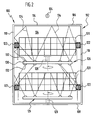
- a illustrated in FIGS. 1 and 2, as a whole designated 100 device is designed for example as a dishwasher and includes a during operation of the device at least temporarily of a liquid, for example of water with detergent additives, through-flowable chamber 102 with an interior 104 bounded by a body 106 of the chamber 102 becomes.
- a liquid for example of water with detergent additives
- the body 106 includes a bottom wall 108, from which two parallel, vertical Side walls 110 and a sidewalls 110 interconnecting vertical rear wall 112 extend upward, and one upper Limiting the interior 104 forming ceiling wall 114 and is at his open front side by means of a pivotable about a horizontal axis 116 Front flap 118 liquid-tight lockable.
- the interior 104 of the chamber 102 occupies one or more, for example two, extracts 120, which, for example, designed as baskets are.
- the trays 120 could be used, for example, as vats, trays, Trays, brackets or the like may be formed.
- Each of the extracts 120 is by means of a respective pull-out guide 122 to the both side walls 110 held so that it (with the front door open 118) along a substantially horizontal extension direction 124 from the interior 104 extendable or against the extension direction 124 completely into the interior 104 of the chamber 102 can be inserted.
- drawer guides 122 are full-extension guides, which allow the respective associated extract 120 substantially complete to withdraw from the interior 104 of the chamber 102.
- each spraying 126 arranged, each one or more rotating about a vertical axis of rotation 128, for example Include spray arms 130, each provided with a plurality of spray nozzles 132 are at the top and / or bottom of each Spray arm 130 are arranged and by means of which a liquid in the Space above or below the respective spray device 126 can be sprayed is.
- this liquid is the Rinsing fluid, which may include in particular water with rinse additives.
- the sprayed during operation of the device 100 liquid is shown in Fig. 2 by the broken lines 134 indicated.
- the sprayed liquid 134 flows through the example as a grid baskets trained extracts 120 with the therein, for example, for cleaning purposes, recorded objects and possibly by the pullout guides 122, then collects at the bottom of the chamber 102 and flows by a (not shown) drain opening from the interior 104 of the Chamber 102 off.
- a first spray device 126 between the bottom wall 108 of the chamber 102 and a lower drawer 120 be arranged while another spray device 126 between two Extents 120, in particular on the underside of an upper extension 120, arranged can be.
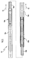
- the guide rails 136 are the Pull-out guides 122, which by means of Wälzoresan extract 138 along the Extension direction 124 are slidably guided together, each with a Variety of liquid passage openings 140 provided, which along the Extension direction 124 follow each other and both an entry of the liquid in the pullout guide 122 as well as an outflow of the liquid (and allow dirt particles contained therein) from the pullout guide 122, as shown schematically in Figs. 3 and 4.
- Fig. 3 is a pullout guide 122 with two guide rails 136 in the extended State shown.
- the pullout guide 122 is in the fully inserted state shown after the device 100 has been put into operation. In In this state, the pullout guide 122 of the in the interior 104 of the Chamber 102 sprayed liquid flushed, the flow directions of this liquid in Fig. 4 schematically indicated by the arrows 142 are.
- the guide rails 136 are preferably formed so that their fluid passage openings 140 in the fully inserted state of the pullout guide 122 with each other and with the fluid passage openings of a in Fig. 4, not shown WälzMechlafigs aligned.
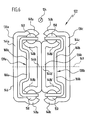
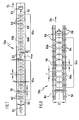
- FIGS. 5 to 11 A concrete example of one for use in a liquid flowed through Chamber 102 particularly suitable drawer slide 122 with three Guide rails is shown in FIGS. 5 to 11 in detail.
- This pullout guide 122 includes a body-side guide rail 136a (see in particular Fig. 7), an extraction-side guide rail 136c (see in particular Fig. 11) and between the body-side guide rail 136a and the outgoing guide rail 136c arranged middle Guide rail 136b (see in particular Fig. 9).
- the middle guide rail is shown 136b by means of a first rolling element arrangement 138a on the body side Guide rail 136a along the extension direction 124 slidably guided.
- the extraction-side guide rail 136c is by means of a second rolling element arrangement 138b on the central guide rail 136b along the extension direction 124 slidably guided.
- the body-side guide rail 136a is shown in Figs. 6 and 7 in detail shown.
- the rail back 144a is different Attachment holes 152 provided, which is the attachment of the body side Guide rail 136a, in particular the passage of fasteners (For example, screws) through the rail back 144 a, serve.
- the rail back 144 a is provided with a stop 153, the interacts with a rolling element cage 166a of the first rolling element arrangement 138a, about the displacement path of the first rolling element arrangement 138a relative to the body-side guide rail 136a to limit.
- the fluid passage openings 140 of the body-side guide rail 136 a are all formed substantially congruent to each other, follow along the Extending direction 124 to each other and are in the extension direction 124 from each other spaced.
- Each of the fluid passage openings 140 is formed substantially rectangular, with rounded corners.
- the extension 1 is each of the Fluid passage openings 140 along the extension direction 124 about 5 mm, while the extent b of each of the fluid passage openings 140 is vertical to the extension direction 124 is approximately 16 mm.
- the entire width B of the Rail back 144a is about 28 mm, and the width L of the web 156 between two consecutive fluid passage openings 140, i. its extension along the extension direction 124 is approximately 5 mm.
- the distance d of the lower edge of each fluid passage opening 140 of the lower edge of the rail back 144a and the upper edge of each of the Fluid passage openings 140 from the upper edge of the rail back 144a is about 5 mm, that is about 18% of the width B of the rail back 144a.
- the rolling elements 150 which on the Wälz analyseslaufbahnen 148 a of the body side Rolling guide rail 136a are each in a receiving hole an upper or a lower WälzSystemhalteang 158 held, wherein Both WälzSystemhalteangn 158 parallel to each other and to the extension direction 124 extend (see Fig. 8).
- Both Wälz stresses 158 are by means of a cage back 160a connected to each other, which extends along the extension direction 124 Parting section 162a having, with a plurality of fluid passage openings 164 is provided.
- the fluid passage openings 164 are substantially congruent with each other formed follow one another along the extension direction 124 and are in the Extension direction 124 spaced from each other.
- Each of the fluid passage openings 164 has substantially the shape of a Rectangles with circle segments attached on two opposite sides on.
- the extension l 'of each fluid passage opening 164 along the extension direction 124 about 8 mm, while the maximum extent b 'of each fluid passage opening 164 is perpendicular to the extension direction 124 is approximately 12 mm.
- the width B 'of the cage back 160a is about 22 mm, while the width of the web 166 between two consecutive in the extension direction 124 fluid passage openings 164 is about 2 mm.
- the area fraction of the fluid passage openings 164 on the total area of the Cage back 160a in the section 162a is about 38%.
- the cage back 160a forms together with the two WälzConsequentlyn 158, the rolling element cage 166a of the first rolling element assembly 138a.
- the rolling elements 150 roll the first rolling element 138a also on two WälzEffbahnen 148b of the middle guide rail 136b, which each one of the rolling element raceways 148a of the body side guide rail 136a are opposite.
- the two WälzConsequentlybahnen 148b are through a rail back 144b connected with each other.
- the middle guide rail 136b further includes another rail back 144b ', which with its flat outside on the flat outside of the rail back 144b abuts and at this, for example by welding, is fixed.
- the rolling element raceways 148b ' are (from the longitudinal center plane 149 of the middle guide rail 136b seen from) convexly curved to a contact surface and a lateral guide for the rolling elements 150 of the second rolling element arrangement To form 138b.
- the rail back 144b ' is in the extension direction 124 forward over the rail back 144b over.
- the rail back 144b is in a portion 154c, which is about the entire length of the rail back 144b extends, with a plurality of Fluid passage openings 140 provided along the extension direction 124th successive and spaced in the extension direction 124 from each other are.
- the fluid passage openings 140 in the rail back 144b are all in the Essentially congruent with each other and have a substantially rectangular shape with rounded corners on.
- the extent I is each of the Fluid passage openings 140 in the extension direction 124 about 5 mm
- the extent b of each of the fluid passage openings 140 is vertical to the extension direction 124 is approximately 10 mm.
- the width B of the rail back 144b is about 18 mm
- the width L of the web 156 between each two in the extension direction 124 consecutive Fluid passage openings 140 that is, the extension of the web 156 in the extension direction 124, about 5 mm. It follows that the Surface portion of the fluid passage openings 140 on the total area of the Rail back 144 b in the portion 154 c is about 28%.
- the distance d of the lower edge of each fluid passage opening 140 of the lower edge of the rail back 144b and the upper edge of each of the Fluid passage openings 140 from the upper edge of the rail back 144b is about 4 mm, that is about 22% of the width B of Rail back 144b.
- the rail back 144b ' is mirror-symmetrical to the rail back 144b formed and thus also with fluid passage openings 140 and a Stopper 168 'provided, which with a WälzMechkafig 166b of the second WälzMechan ist 138b cooperates to the displacement of the second rolling element assembly 138b relative to the middle guide rail 136b limit.
- the two rail backs 144b, 144b 'of the middle guide rail 136b are so fixed to one another that the fluid passage openings 140 of the Rail back 144 b in the overlap region of both rail back 144b, 144b 'each having a fluid passage opening 140 of the rail back 144b 'are aligned.
- the rolling elements 150 of the second rolling element arrangement 138b are in the form of spheres formed and in Wälz analysesabilityö Samuelen two Wälz stresseshalteartn 158 (see FIG. 10), which passes through a cage back 160b are interconnected and together with the same the Wälz stresses hisfig 166b of the second rolling element assembly 138 form.
- the cage back 160b is in a portion 162b that extends over almost the entire length of the cage back 160b extends, with a plurality of fluid passage openings 164, which is essentially congruent are formed with each other, follow one another along the extension direction 124 and spaced apart in the extension direction 124.
- the fluid passage openings 164 the cage back 160b of the second Wälz analysesan onion 138b dimensioned the same and spaced from each other by the same distance L ' Fluid passage openings 164 of the cage back 160a of the first rolling element arrangement 138a.
- this specific embodiment also has the cage back 160b the same width B 'as the cage back 160a of the first Wälz redesignan effet 138a, so that also the surface portion of the fluid passage openings 164 on the entire surface of the cage back 160b in the section 162b is the same size as in the section 162a of the cage back 160a of the first rolling element assembly 138a.
- the extraction side guide rail 136c includes, as best seen in FIG is seen, two WälzSystemterrorismen 148c, which each one of the WälzSystemlaufbahnen 148b 'of the middle guide rail 136b opposite and (from the longitudinal center plane 149 of the extraction-side guide rail 136c seen from) are concave, so that the WälzSystemlaufbahnen 148c the discharge-side guide rail 136c to the rolling elements 150 of the second WälzConsequentlyanssen 138b provide a contact surface and a lateral guide.
- the rolling element raceways 148c are through a rail back 144c connected with each other.
- the rail back 144c is with mounting holes 174, which serve to receive fastening means, by means of which the extension 120 with the extraction-side guide rail 136c is connectable.
- the rail back 144c has two sections 154d and 154e, which extend along the direction of extension 124, approximately over one-sixth or over about two-thirds of the length of the rail back 144c.
- Each of the sections 154d, 154e of the rail back 154c has a plurality from fluid passage openings 140, which is substantially congruent are formed with each other, follow one another along the extension direction 124 and spaced apart in the extension direction 124.
- the fluid passage openings 140 of the rail back 144c the same dimensioned and around the same Distance L in the extension direction 124 spaced from each other as the fluid passage openings 140 of the rail back 144 a of the body side guide rail 136a. Since in this particular embodiment, the width B of the rail back 144c having the width B of the rail back 144a of FIG Corpus lake guide rail 136a matches, is also the area ratio the fluid passage openings 140 on the entire surface of the rail back 144c in the sections 154d and 154e of the rail back 144c the same size as in the sections 154a and 154b of the rail back 144a of the body-side guide rail 136a.
- each Fluid passage opening 140 and the upper edge or the lower edge of the Rail back 144c is the same size as in this embodiment the fluid passage openings 140 of the body-side guide rail 136 a.
- the guide rails 136a, 136b and 136c are preferably made of a stainless steel material produced, which has the advantage of increased Corrosion resistance when using dirt - dissolving detergent additives in the liquid used in the interior 104 of the chamber 102 provides. In addition, this material reduces the susceptibility to the pullout guide 122 remaining rinsing residues, especially against acidic or basic food residues or the like.
- the Wälz stresseskorfige 166a, 166b and the rolling elements 150 are made For the reasons mentioned, preferably made of a stainless steel material produced.
- the radii of the spherical rolling elements 150 on the one hand and the radii of curvature the rolling element raceways 148a, 148b, 148b 'and 148c on the other are preferably coordinated so that each rolling element 150th each rolling element track assigned to it is not along a line but in each case only touched at one point.
- the fluid passage openings 140, 164 in the guide rails or the WälzShigen can by any suitable separation method, in particular by punching or by laser cutting.
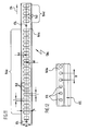
- the rolling element raceways 148a, 148b, 148b 'and / or 148c in their respective end regions 175 each with one or more fluid passage openings 176th are provided, which a drain of residual fluid from the respective Enable rolling element raceway.
- these passage openings in the end region of a rolling body raceway serve a certain latching effect for one or more Rolling element 150 in an extended position of the pullout guide 122 to achieve.
- the fluid passage openings 176 are in the end region 175 of the relevant rolling body raceway substantially circular formed and arranged at a distance D from each other, which the Distance between two rolling elements 150 on one of the Wälz stresseskorfige 166a, 166b equivalent.
- FIG. 1 A plan view of such an end region 175 with fluid passage openings 176 is the example of the rolling body 148a of the body side guide rail 136a is shown in FIG.
Landscapes
- Engineering & Computer Science (AREA)
- General Engineering & Computer Science (AREA)
- Mechanical Engineering (AREA)
- Drawers Of Furniture (AREA)
- Washing And Drying Of Tableware (AREA)
Priority Applications (1)
| Application Number | Priority Date | Filing Date | Title |
|---|---|---|---|
| DE202004021631U DE202004021631U1 (de) | 2004-01-09 | 2004-12-22 | Vorrichtung mit einer von einem Fluid durchströmbaren Kammer |
Applications Claiming Priority (2)
| Application Number | Priority Date | Filing Date | Title |
|---|---|---|---|
| DE102004001402 | 2004-01-09 | ||
| DE102004001402A DE102004001402A1 (de) | 2004-01-09 | 2004-01-09 | Vorrichtung mit einer von einem Fluid durchströmbaren Kammer und Verwendung einer Auszugsführung in einer solchen Vorrichtung |
Publications (3)
| Publication Number | Publication Date |
|---|---|
| EP1552781A2 true EP1552781A2 (fr) | 2005-07-13 |
| EP1552781A3 EP1552781A3 (fr) | 2008-09-03 |
| EP1552781B1 EP1552781B1 (fr) | 2009-10-21 |
Family
ID=34585368
Family Applications (1)
| Application Number | Title | Priority Date | Filing Date |
|---|---|---|---|
| EP04030389A Expired - Lifetime EP1552781B1 (fr) | 2004-01-09 | 2004-12-22 | Lave-vaisselle avec glissières d'extraction du panier. |
Country Status (3)
| Country | Link |
|---|---|
| EP (1) | EP1552781B1 (fr) |
| AT (1) | ATE446042T1 (fr) |
| DE (3) | DE102004001402A1 (fr) |
Cited By (9)
| Publication number | Priority date | Publication date | Assignee | Title |
|---|---|---|---|---|
| EP1800590A1 (fr) * | 2005-12-23 | 2007-06-27 | Aktiebolaget SKF | Support pour guide du panier de lave-vaisselle |
| EP1854395A1 (fr) * | 2006-05-09 | 2007-11-14 | Whirlpool Corporation | Lave-vaisselle avec porte-utensiles et ses glissières correspondantes |
| EP1982633A1 (fr) * | 2007-04-16 | 2008-10-22 | Whirlpool Corporation | Lave-vaisselle à bâti monté sur rails et chaînes à rouleaux correspondantes |
| DE202008014265U1 (de) * | 2008-10-27 | 2010-04-15 | Paul Hettich Gmbh & Co. Kg | Auszugsführung für Backöfen |
| ITRE20110094A1 (it) * | 2011-11-08 | 2013-05-09 | Silvio Rocchi | Cestello porta vassoi di tipo estraibile a cassetto su guide portanti per autoclave sterilizzatrice |
| DE102013211549A1 (de) | 2013-06-19 | 2014-12-24 | BSH Bosch und Siemens Hausgeräte GmbH | Geschirrspülmaschine |
| EP3345505A1 (fr) * | 2017-01-05 | 2018-07-11 | LG Electronics Inc. | Appareil ménager comprenant un rail de tiroir |
| CN109907715A (zh) * | 2019-04-12 | 2019-06-21 | 广东洁诺生活电器有限公司 | 一种抽屉式洗碗机 |
| CN109907710A (zh) * | 2019-03-28 | 2019-06-21 | 广东洁诺生活电器有限公司 | 一种洗碗机中喷臂结构 |
Families Citing this family (4)
| Publication number | Priority date | Publication date | Assignee | Title |
|---|---|---|---|---|
| DE102012100202A1 (de) | 2012-01-11 | 2013-07-11 | Druck- und Spritzgußwerk Hettich GmbH & Co. KG | Auszugsführung |
| DE102015109220A1 (de) | 2015-06-10 | 2016-12-15 | Paul Hettich Gmbh & Co. Kg | Auszugsführung für ein Spülgerät und Spülgerät |
| CN106377213B (zh) * | 2016-10-14 | 2023-07-14 | 佛山市顺德区美的洗涤电器制造有限公司 | 导轨组件及用水家用电器 |
| DE102022102920A1 (de) | 2022-02-08 | 2023-08-10 | Schock Metallwerk Gmbh. | Auszugführung |
Family Cites Families (3)
| Publication number | Priority date | Publication date | Assignee | Title |
|---|---|---|---|---|
| SE302507B (fr) * | 1967-11-16 | 1968-07-22 | Electrolux Ab | |
| US5061020A (en) * | 1990-07-30 | 1991-10-29 | White Consolidated Industries, Inc. | Dishwasher rack channel cap |
| DE10248512B4 (de) * | 2002-10-17 | 2007-03-01 | Electrolux Home Products Corporation N.V. | Geschirraufnahme und -transportvorrichtung und Geschirrspülmaschine |
-
2004
- 2004-01-09 DE DE102004001402A patent/DE102004001402A1/de not_active Withdrawn
- 2004-12-22 EP EP04030389A patent/EP1552781B1/fr not_active Expired - Lifetime
- 2004-12-22 DE DE202004021631U patent/DE202004021631U1/de not_active Expired - Lifetime
- 2004-12-22 AT AT04030389T patent/ATE446042T1/de active
- 2004-12-22 DE DE502004010261T patent/DE502004010261D1/de not_active Expired - Lifetime
Cited By (12)
| Publication number | Priority date | Publication date | Assignee | Title |
|---|---|---|---|---|
| EP1800590A1 (fr) * | 2005-12-23 | 2007-06-27 | Aktiebolaget SKF | Support pour guide du panier de lave-vaisselle |
| EP1854395A1 (fr) * | 2006-05-09 | 2007-11-14 | Whirlpool Corporation | Lave-vaisselle avec porte-utensiles et ses glissières correspondantes |
| EP1982633A1 (fr) * | 2007-04-16 | 2008-10-22 | Whirlpool Corporation | Lave-vaisselle à bâti monté sur rails et chaînes à rouleaux correspondantes |
| DE202008014265U1 (de) * | 2008-10-27 | 2010-04-15 | Paul Hettich Gmbh & Co. Kg | Auszugsführung für Backöfen |
| ITRE20110094A1 (it) * | 2011-11-08 | 2013-05-09 | Silvio Rocchi | Cestello porta vassoi di tipo estraibile a cassetto su guide portanti per autoclave sterilizzatrice |
| DE102013211549A1 (de) | 2013-06-19 | 2014-12-24 | BSH Bosch und Siemens Hausgeräte GmbH | Geschirrspülmaschine |
| DE102013211549B4 (de) * | 2013-06-19 | 2017-09-21 | BSH Hausgeräte GmbH | Geschirrspülmaschine |
| EP3345505A1 (fr) * | 2017-01-05 | 2018-07-11 | LG Electronics Inc. | Appareil ménager comprenant un rail de tiroir |
| US10517397B2 (en) | 2017-01-05 | 2019-12-31 | Lg Electronics Inc. | Drawer rail and home appliance including the same |
| US10842268B2 (en) | 2017-01-05 | 2020-11-24 | Lg Electronics Inc. | Drawer rail and home appliance including the same |
| CN109907710A (zh) * | 2019-03-28 | 2019-06-21 | 广东洁诺生活电器有限公司 | 一种洗碗机中喷臂结构 |
| CN109907715A (zh) * | 2019-04-12 | 2019-06-21 | 广东洁诺生活电器有限公司 | 一种抽屉式洗碗机 |
Also Published As
| Publication number | Publication date |
|---|---|
| DE202004021631U1 (de) | 2009-09-03 |
| EP1552781B1 (fr) | 2009-10-21 |
| ATE446042T1 (de) | 2009-11-15 |
| DE502004010261D1 (de) | 2009-12-03 |
| DE102004001402A1 (de) | 2005-08-04 |
| EP1552781A3 (fr) | 2008-09-03 |
Similar Documents
| Publication | Publication Date | Title |
|---|---|---|
| EP1552781B1 (fr) | Lave-vaisselle avec glissières d'extraction du panier. | |
| DE4108516C2 (de) | Hochgeschwindigkeits-Beizvorrichtung und Hochgeschwindigkeits-Beizverfahren | |
| DE3014276A1 (de) | Fuehrung fuer einen an einem tisch o.dgl. angebrachten auszug | |
| EP0459307A2 (fr) | Dispositif filtrant comportant plusieurs éléments filtrants tubulaires | |
| DE102006007442A1 (de) | Reinigungsvorrichtung für ein Bauteil eines Haushaltswäschetrockners | |
| EP2186438B1 (fr) | Guidage d'extraction de meuble | |
| EP3747338A1 (fr) | Panier pour laves-vaisselles | |
| DE19926962A1 (de) | Geschirrspülmaschine mit höhenverstellbarem Korb | |
| DE2813236A1 (de) | Filterpresse mit einer abspritzeinrichtung | |
| EP3307113A1 (fr) | Dispositif de guidage d'extraction pour un appareil de lavage et appareil de lavage | |
| EP1967297B1 (fr) | Dispositif de nettoyage de caisses | |
| DE102019109076A1 (de) | Bodenschwelle und Türanordnung | |
| DE102011005509A1 (de) | Auszugseinrichtung | |
| EP0056238B1 (fr) | Dispositif de drainage pour terrains de sport | |
| DE2823333C2 (fr) | ||
| DE102005043226C5 (de) | Koksofenbedienungseinrichtung und Koksofen mit wenigstens einer solchen Bedienungseinrichtung | |
| DE2358833A1 (de) | Fahrbare portalwaschanlage fuer fahrzeuge | |
| DE2845876A1 (de) | Schiebetuer fuer eine duschkabine | |
| EP0613639A2 (fr) | Glissières pour tiroirs | |
| DE102016100597A1 (de) | Vorrichtung und Verfahren zum Reinigen von Pinseln | |
| DE4327688A1 (de) | Auszugführung | |
| DE3306537A1 (de) | Strangfuehrung fuer eine stranggussmaschine | |
| DE102013210015B4 (de) | Führungsschiene für eine Geschirrspülmaschine | |
| DE1403634A1 (de) | Reinigungsmaschine fuer feste Gegenstaende,insbesondere Kuechengeschirr | |
| DE2061781A1 (en) | Rectifier with multiple trays - has secondary slopes within trays to improve performance |
Legal Events
| Date | Code | Title | Description |
|---|---|---|---|
| PUAI | Public reference made under article 153(3) epc to a published international application that has entered the european phase |
Free format text: ORIGINAL CODE: 0009012 |
|
| AK | Designated contracting states |
Kind code of ref document: A2 Designated state(s): AT BE BG CH CY CZ DE DK EE ES FI FR GB GR HU IE IS IT LI LT LU MC NL PL PT RO SE SI SK TR |
|
| AX | Request for extension of the european patent |
Extension state: AL BA HR LV MK YU |
|
| PUAL | Search report despatched |
Free format text: ORIGINAL CODE: 0009013 |
|
| AK | Designated contracting states |
Kind code of ref document: A3 Designated state(s): AT BE BG CH CY CZ DE DK EE ES FI FR GB GR HU IE IS IT LI LT LU MC NL PL PT RO SE SI SK TR |
|
| AX | Request for extension of the european patent |
Extension state: AL BA HR LV MK YU |
|
| 17P | Request for examination filed |
Effective date: 20090226 |
|
| GRAP | Despatch of communication of intention to grant a patent |
Free format text: ORIGINAL CODE: EPIDOSNIGR1 |
|
| AKX | Designation fees paid |
Designated state(s): AT BE BG CH CY CZ DE DK EE ES FI FR GB GR HU IE IS IT LI LT LU MC NL PL PT RO SE SI SK TR |
|
| GRAS | Grant fee paid |
Free format text: ORIGINAL CODE: EPIDOSNIGR3 |
|
| GRAA | (expected) grant |
Free format text: ORIGINAL CODE: 0009210 |
|
| AK | Designated contracting states |
Kind code of ref document: B1 Designated state(s): AT BE BG CH CY CZ DE DK EE ES FI FR GB GR HU IE IS IT LI LT LU MC NL PL PT RO SE SI SK TR |
|
| REG | Reference to a national code |
Ref country code: GB Ref legal event code: FG4D Free format text: NOT ENGLISH |
|
| REG | Reference to a national code |
Ref country code: CH Ref legal event code: NV Representative=s name: ISLER & PEDRAZZINI AG Ref country code: CH Ref legal event code: EP |
|
| REG | Reference to a national code |
Ref country code: IE Ref legal event code: FG4D |
|
| REF | Corresponds to: |
Ref document number: 502004010261 Country of ref document: DE Date of ref document: 20091203 Kind code of ref document: P |
|
| LTIE | Lt: invalidation of european patent or patent extension |
Effective date: 20091021 |
|
| NLV1 | Nl: lapsed or annulled due to failure to fulfill the requirements of art. 29p and 29m of the patents act | ||
| PG25 | Lapsed in a contracting state [announced via postgrant information from national office to epo] |
Ref country code: IS Free format text: LAPSE BECAUSE OF FAILURE TO SUBMIT A TRANSLATION OF THE DESCRIPTION OR TO PAY THE FEE WITHIN THE PRESCRIBED TIME-LIMIT Effective date: 20100221 Ref country code: SE Free format text: LAPSE BECAUSE OF FAILURE TO SUBMIT A TRANSLATION OF THE DESCRIPTION OR TO PAY THE FEE WITHIN THE PRESCRIBED TIME-LIMIT Effective date: 20091021 Ref country code: LT Free format text: LAPSE BECAUSE OF FAILURE TO SUBMIT A TRANSLATION OF THE DESCRIPTION OR TO PAY THE FEE WITHIN THE PRESCRIBED TIME-LIMIT Effective date: 20091021 Ref country code: ES Free format text: LAPSE BECAUSE OF FAILURE TO SUBMIT A TRANSLATION OF THE DESCRIPTION OR TO PAY THE FEE WITHIN THE PRESCRIBED TIME-LIMIT Effective date: 20100201 Ref country code: FI Free format text: LAPSE BECAUSE OF FAILURE TO SUBMIT A TRANSLATION OF THE DESCRIPTION OR TO PAY THE FEE WITHIN THE PRESCRIBED TIME-LIMIT Effective date: 20091021 Ref country code: PT Free format text: LAPSE BECAUSE OF FAILURE TO SUBMIT A TRANSLATION OF THE DESCRIPTION OR TO PAY THE FEE WITHIN THE PRESCRIBED TIME-LIMIT Effective date: 20100222 |
|
| REG | Reference to a national code |
Ref country code: IE Ref legal event code: FD4D |
|
| PG25 | Lapsed in a contracting state [announced via postgrant information from national office to epo] |
Ref country code: PL Free format text: LAPSE BECAUSE OF FAILURE TO SUBMIT A TRANSLATION OF THE DESCRIPTION OR TO PAY THE FEE WITHIN THE PRESCRIBED TIME-LIMIT Effective date: 20091021 Ref country code: SI Free format text: LAPSE BECAUSE OF FAILURE TO SUBMIT A TRANSLATION OF THE DESCRIPTION OR TO PAY THE FEE WITHIN THE PRESCRIBED TIME-LIMIT Effective date: 20091021 |
|
| BERE | Be: lapsed |
Owner name: SCHOCK METALLWERK G.M.B.H. Effective date: 20091231 |
|
| PLBI | Opposition filed |
Free format text: ORIGINAL CODE: 0009260 |
|
| PG25 | Lapsed in a contracting state [announced via postgrant information from national office to epo] |
Ref country code: EE Free format text: LAPSE BECAUSE OF FAILURE TO SUBMIT A TRANSLATION OF THE DESCRIPTION OR TO PAY THE FEE WITHIN THE PRESCRIBED TIME-LIMIT Effective date: 20091021 Ref country code: MC Free format text: LAPSE BECAUSE OF NON-PAYMENT OF DUE FEES Effective date: 20100701 Ref country code: BG Free format text: LAPSE BECAUSE OF FAILURE TO SUBMIT A TRANSLATION OF THE DESCRIPTION OR TO PAY THE FEE WITHIN THE PRESCRIBED TIME-LIMIT Effective date: 20100121 Ref country code: IE Free format text: LAPSE BECAUSE OF FAILURE TO SUBMIT A TRANSLATION OF THE DESCRIPTION OR TO PAY THE FEE WITHIN THE PRESCRIBED TIME-LIMIT Effective date: 20091021 Ref country code: DK Free format text: LAPSE BECAUSE OF FAILURE TO SUBMIT A TRANSLATION OF THE DESCRIPTION OR TO PAY THE FEE WITHIN THE PRESCRIBED TIME-LIMIT Effective date: 20091021 Ref country code: RO Free format text: LAPSE BECAUSE OF FAILURE TO SUBMIT A TRANSLATION OF THE DESCRIPTION OR TO PAY THE FEE WITHIN THE PRESCRIBED TIME-LIMIT Effective date: 20091021 |
|
| PLAX | Notice of opposition and request to file observation + time limit sent |
Free format text: ORIGINAL CODE: EPIDOSNOBS2 |
|
| 26 | Opposition filed |
Opponent name: HETTICH MANAGEMENT SERVICE GMBH Effective date: 20100721 Opponent name: MIELE & CIE. KG Effective date: 20100720 |
|
| PG25 | Lapsed in a contracting state [announced via postgrant information from national office to epo] |
Ref country code: SK Free format text: LAPSE BECAUSE OF FAILURE TO SUBMIT A TRANSLATION OF THE DESCRIPTION OR TO PAY THE FEE WITHIN THE PRESCRIBED TIME-LIMIT Effective date: 20091021 Ref country code: CZ Free format text: LAPSE BECAUSE OF FAILURE TO SUBMIT A TRANSLATION OF THE DESCRIPTION OR TO PAY THE FEE WITHIN THE PRESCRIBED TIME-LIMIT Effective date: 20091021 |
|
| GBPC | Gb: european patent ceased through non-payment of renewal fee |
Effective date: 20100121 |
|
| PG25 | Lapsed in a contracting state [announced via postgrant information from national office to epo] |
Ref country code: GR Free format text: LAPSE BECAUSE OF FAILURE TO SUBMIT A TRANSLATION OF THE DESCRIPTION OR TO PAY THE FEE WITHIN THE PRESCRIBED TIME-LIMIT Effective date: 20100122 Ref country code: BE Free format text: LAPSE BECAUSE OF NON-PAYMENT OF DUE FEES Effective date: 20091231 |
|
| PG25 | Lapsed in a contracting state [announced via postgrant information from national office to epo] |
Ref country code: GB Free format text: LAPSE BECAUSE OF NON-PAYMENT OF DUE FEES Effective date: 20100121 |
|
| PLBB | Reply of patent proprietor to notice(s) of opposition received |
Free format text: ORIGINAL CODE: EPIDOSNOBS3 |
|
| PG25 | Lapsed in a contracting state [announced via postgrant information from national office to epo] |
Ref country code: LU Free format text: LAPSE BECAUSE OF NON-PAYMENT OF DUE FEES Effective date: 20091222 |
|
| PG25 | Lapsed in a contracting state [announced via postgrant information from national office to epo] |
Ref country code: HU Free format text: LAPSE BECAUSE OF FAILURE TO SUBMIT A TRANSLATION OF THE DESCRIPTION OR TO PAY THE FEE WITHIN THE PRESCRIBED TIME-LIMIT Effective date: 20100422 |
|
| PG25 | Lapsed in a contracting state [announced via postgrant information from national office to epo] |
Ref country code: CY Free format text: LAPSE BECAUSE OF FAILURE TO SUBMIT A TRANSLATION OF THE DESCRIPTION OR TO PAY THE FEE WITHIN THE PRESCRIBED TIME-LIMIT Effective date: 20091021 |
|
| PG25 | Lapsed in a contracting state [announced via postgrant information from national office to epo] |
Ref country code: NL Free format text: LAPSE BECAUSE OF FAILURE TO SUBMIT A TRANSLATION OF THE DESCRIPTION OR TO PAY THE FEE WITHIN THE PRESCRIBED TIME-LIMIT Effective date: 20091021 |
|
| REG | Reference to a national code |
Ref country code: DE Ref legal event code: R100 Ref document number: 502004010261 Country of ref document: DE |
|
| PLCK | Communication despatched that opposition was rejected |
Free format text: ORIGINAL CODE: EPIDOSNREJ1 |
|
| PLBN | Opposition rejected |
Free format text: ORIGINAL CODE: 0009273 |
|
| STAA | Information on the status of an ep patent application or granted ep patent |
Free format text: STATUS: OPPOSITION REJECTED |
|
| 27O | Opposition rejected |
Effective date: 20131205 |
|
| REG | Reference to a national code |
Ref country code: DE Ref legal event code: R100 Ref document number: 502004010261 Country of ref document: DE Effective date: 20131205 |
|
| REG | Reference to a national code |
Ref country code: DE Ref legal event code: R082 Ref document number: 502004010261 Country of ref document: DE Representative=s name: HOEGER, STELLRECHT & PARTNER PATENTANWAELTE MB, DE |
|
| REG | Reference to a national code |
Ref country code: FR Ref legal event code: PLFP Year of fee payment: 12 |
|
| REG | Reference to a national code |
Ref country code: FR Ref legal event code: PLFP Year of fee payment: 13 |
|
| REG | Reference to a national code |
Ref country code: FR Ref legal event code: PLFP Year of fee payment: 14 |
|
| REG | Reference to a national code |
Ref country code: DE Ref legal event code: R082 Ref document number: 502004010261 Country of ref document: DE Representative=s name: DTS PATENT- UND RECHTSANWAELTE SCHNEKENBUEHL U, DE Ref country code: DE Ref legal event code: R082 Ref document number: 502004010261 Country of ref document: DE Representative=s name: HOEGER, STELLRECHT & PARTNER PATENTANWAELTE MB, DE |
|
| REG | Reference to a national code |
Ref country code: DE Ref legal event code: R082 Ref document number: 502004010261 Country of ref document: DE Representative=s name: DTS PATENT- UND RECHTSANWAELTE SCHNEKENBUEHL U, DE Ref country code: DE Ref legal event code: R082 Ref document number: 502004010261 Country of ref document: DE Representative=s name: DTS PATENT- UND RECHTSANWAELTE PARTMBB, DE |
|
| PGFP | Annual fee paid to national office [announced via postgrant information from national office to epo] |
Ref country code: FR Payment date: 20221219 Year of fee payment: 19 Ref country code: AT Payment date: 20221216 Year of fee payment: 19 |
|
| PGFP | Annual fee paid to national office [announced via postgrant information from national office to epo] |
Ref country code: TR Payment date: 20221221 Year of fee payment: 19 Ref country code: CH Payment date: 20230103 Year of fee payment: 19 |
|
| PGFP | Annual fee paid to national office [announced via postgrant information from national office to epo] |
Ref country code: IT Payment date: 20221230 Year of fee payment: 19 |
|
| P01 | Opt-out of the competence of the unified patent court (upc) registered |
Effective date: 20230601 |
|
| PGFP | Annual fee paid to national office [announced via postgrant information from national office to epo] |
Ref country code: DE Payment date: 20231214 Year of fee payment: 20 |
|
| REG | Reference to a national code |
Ref country code: CH Ref legal event code: PL |
|
| REG | Reference to a national code |
Ref country code: AT Ref legal event code: MM01 Ref document number: 446042 Country of ref document: AT Kind code of ref document: T Effective date: 20231222 |
|
| PG25 | Lapsed in a contracting state [announced via postgrant information from national office to epo] |
Ref country code: FR Free format text: LAPSE BECAUSE OF NON-PAYMENT OF DUE FEES Effective date: 20231231 |
|
| PG25 | Lapsed in a contracting state [announced via postgrant information from national office to epo] |
Ref country code: CH Free format text: LAPSE BECAUSE OF NON-PAYMENT OF DUE FEES Effective date: 20231231 |
|
| PG25 | Lapsed in a contracting state [announced via postgrant information from national office to epo] |
Ref country code: AT Free format text: LAPSE BECAUSE OF NON-PAYMENT OF DUE FEES Effective date: 20231222 |
|
| PG25 | Lapsed in a contracting state [announced via postgrant information from national office to epo] |
Ref country code: FR Free format text: LAPSE BECAUSE OF NON-PAYMENT OF DUE FEES Effective date: 20231231 Ref country code: CH Free format text: LAPSE BECAUSE OF NON-PAYMENT OF DUE FEES Effective date: 20231231 Ref country code: AT Free format text: LAPSE BECAUSE OF NON-PAYMENT OF DUE FEES Effective date: 20231222 |
|
| REG | Reference to a national code |
Ref country code: DE Ref legal event code: R071 Ref document number: 502004010261 Country of ref document: DE |
|
| PG25 | Lapsed in a contracting state [announced via postgrant information from national office to epo] |
Ref country code: IT Free format text: LAPSE BECAUSE OF NON-PAYMENT OF DUE FEES Effective date: 20231222 |
|
| PG25 | Lapsed in a contracting state [announced via postgrant information from national office to epo] |
Ref country code: TR Free format text: LAPSE BECAUSE OF NON-PAYMENT OF DUE FEES Effective date: 20231222 |