EP3747338A1 - Panier pour laves-vaisselles - Google Patents
Panier pour laves-vaisselles Download PDFInfo
- Publication number
- EP3747338A1 EP3747338A1 EP20173387.0A EP20173387A EP3747338A1 EP 3747338 A1 EP3747338 A1 EP 3747338A1 EP 20173387 A EP20173387 A EP 20173387A EP 3747338 A1 EP3747338 A1 EP 3747338A1
- Authority
- EP
- European Patent Office
- Prior art keywords
- basket
- washing
- plane
- deflecting surface
- interior
- Prior art date
- Legal status (The legal status is an assumption and is not a legal conclusion. Google has not performed a legal analysis and makes no representation as to the accuracy of the status listed.)
- Granted
Links
Images




Classifications
-
- A—HUMAN NECESSITIES
- A47—FURNITURE; DOMESTIC ARTICLES OR APPLIANCES; COFFEE MILLS; SPICE MILLS; SUCTION CLEANERS IN GENERAL
- A47L—DOMESTIC WASHING OR CLEANING; SUCTION CLEANERS IN GENERAL
- A47L15/00—Washing or rinsing machines for crockery or tableware
- A47L15/42—Details
- A47L15/50—Racks ; Baskets
-
- A—HUMAN NECESSITIES
- A47—FURNITURE; DOMESTIC ARTICLES OR APPLIANCES; COFFEE MILLS; SPICE MILLS; SUCTION CLEANERS IN GENERAL
- A47L—DOMESTIC WASHING OR CLEANING; SUCTION CLEANERS IN GENERAL
- A47L15/00—Washing or rinsing machines for crockery or tableware
- A47L15/42—Details
- A47L15/50—Racks ; Baskets
- A47L15/501—Baskets, e.g. for conveyor-type, in-sink type or hood-type machines
-
- A—HUMAN NECESSITIES
- A47—FURNITURE; DOMESTIC ARTICLES OR APPLIANCES; COFFEE MILLS; SPICE MILLS; SUCTION CLEANERS IN GENERAL
- A47L—DOMESTIC WASHING OR CLEANING; SUCTION CLEANERS IN GENERAL
- A47L15/00—Washing or rinsing machines for crockery or tableware
- A47L15/42—Details
- A47L15/4278—Nozzles
- A47L15/428—Rotary nozzles
Definitions
- the present invention relates to a wash basket for dishwashers, the wash basket having a lattice-shaped basket base and side walls and the side walls with the lattice-shaped basket base together surround a basket interior of the wash basket and the basket base and / or the side walls on an underside of the wash basket have contact surfaces which are in a The contact plane of the wash basket ends, with at least one wash liquid deflecting surface being formed in at least one of the side walls for deflecting a jet of wash liquid penetrating the contact plane into the interior of the basket and the wash liquid deflecting surface extending between an inner wall section of the side wall and an outer wall section of the side wall, the outer wall section from the interior of the basket is arranged from seen further out than the inner wall portion.
- the invention also relates to an arrangement with a dishwasher and a washing basket and a method for washing objects arranged in the interior of a washing basket in a dishwasher.
- washing baskets of the generic type are used for washing dishes, glasses, cutlery and the like in dishwashers.
- washing racks can also be used for washing other items in dishwashers.
- a wash basket of the type mentioned is z. B. in the EP 1 287 780 B1 shown.
- the rinsing liquid deflecting surfaces are designed as strips running parallel to the contact plane.
- washing baskets of the generic type improve so that they contribute to the best possible washing result.
- the rinsing liquid deflecting surface has at least one deflecting surface area which, seen in a sectional plane parallel to the support plane, is arranged at an obtuse angle relative to an inner surface of the inner wall section facing the basket interior, this deflecting surface area in a Height direction normal to the contact plane has a height extension of at least 5 mm, preferably of at least 10 mm.
- the washing liquid deflecting surface has at least one deflecting surface area which, seen in the sectional plane parallel to the standing plane, is at an obtuse angle relative to the inner space facing the basket interior Surface of the inner wall portion is arranged.
- this deflecting surface area has at least the height extension mentioned above in the height direction normal to the contact plane.
- the concept of the inner surface is to be understood in the sense of an inner surface, which is the surface that faces the interior of the basket.
- the invention achieves that the washing liquid entering the side wall is deflected in a kind of 3D effect at the washing liquid deflecting surfaces according to the invention, so that the objects to be washed stored in the basket interior are exposed to washing liquid from as many different sides as possible. In this way, it is at least largely avoided that there are areas of the objects to be washed that are not exposed to washing liquid. Overall, the washing result is thus compared with these washing liquid deflecting surfaces designed according to the invention the prior art significantly improved.
- washing liquid deflecting surfaces according to the invention with corresponding deflecting surface areas are in a side wall, which, viewed in the cutting plane parallel to the standing plane, are arranged at an obtuse angle relative to the inner surface of the inner wall section facing the basket interior. With these angles, the respective deflecting surface area and the directly adjoining inner surface of the inner wall section must always be considered.
- the stated obtuse angles are advantageously in an interval from 91 ° to 160 °, preferably from 95 ° to 140 °.
- preferred embodiments of the invention provide that the deflecting surface area, which, seen in the cutting plane parallel to the standing plane, is at the obtuse angle relative to the inner surface of the basket interior facing inner wall section is arranged, in addition, viewed in a cutting plane orthogonal to the contact plane, includes an acute angle with the contact plane.
- the rinsing liquid deflecting surfaces can also have deflecting surface areas which, viewed in a sectional plane orthogonal to the contact plane, enclose an acute angle with the contact plane.
- the last-mentioned deflecting surface areas of the rinsing liquid deflecting surface are then oriented as is known per se in the prior art mentioned at the beginning.
- the deflecting surface areas according to the invention can be designed to be flat in themselves, but also to be curved in themselves. So that the deflecting surface areas can develop a corresponding effect, it is expediently provided that the deflecting surface area, seen in the cutting plane parallel to the support plane, has an extent measured along the deflecting surface area between the inner surface of the inner wall section and an inner surface of the outer wall section facing the interior of the basket of at least 5 mm, preferably of at least 10 mm.
- two of the deflecting surface areas of the rinsing liquid deflecting surface arranged at the obtuse angle relative to an inner surface of the inner wall section facing the basket interior jointly and directly adjoin the outer wall section on opposite sides .
- Particularly preferred variants provide that these two deflecting surface areas or at least imaginary extensions thereof, viewed in the cutting plane parallel to the standing plane, intersect in the outer wall section or outside the washing rack. This ensures in a particularly simple manner that the rinsing liquid jets reflected on the deflecting surface areas are reflected into the interior of the basket.
- the rinsing liquid deflecting surface together with an inner surface of the outer wall section facing the basket interior delimits an indentation in the side wall that is open towards the support plane and towards the basket interior.
- the rinsing liquid deflecting surface together with the inner surface of the outer wall section forms a structure in the form of an indentation on which rinsing liquid entering the side wall at the corresponding point is deflected in various directions into the basket interior.
- a shell-shaped indentation the term shell being understood to mean that the most varied shapes or courses or configurations of the flushing liquid deflecting surface and the inner surface of the outer wall section are possible.
- the flushing liquid deflecting surface is curved in itself or angled one or more times.
- a cross-sectional width of the indentation measured parallel to the standing plane and parallel to the inner surface of the outer wall section, increases, preferably continuously, in the direction of the interior of the basket.
- the flushing liquid deflecting surface closes off the indentation at its end opposite the contact plane with a self-contained deflecting surface area of the flushing liquid deflecting surface.
- Dishwashing racks according to the invention can be used for washing dishes, glasses, cutlery, but also other objects, in correspondingly suitable dishwashers.
- the washing racks according to the invention can be used accordingly both in the catering sector and in industrial production.
- washing baskets according to the invention can also be equipped with lids or the like, optionally latticed.
- the washing baskets can be made of different materials. It is preferably a plastic wash baskets.
- the bottom webs and the side walls, preferably the entire washing basket, can or can be formed in one piece.
- the washing racks according to the invention can e.g. are manufactured by injection molding.
- the terms above and below refer to an operating position of the wash basket in which the basket base forms the lower end of the wash basket and usually stands on a horizontal surface, i.e. the contact plane is a horizontal plane.
- the term of the lattice-shaped basket base describes that the basket base has free spaces or through-openings between the base webs through which e.g. the rinsing liquid can enter the basket interior through the basket bottom.
- the washing basket When viewed from above on the washing basket, the washing basket, as is known per se, can have a rectangular, in particular square, but also a differently shaped basic shape.
- the term rectangular or square basic shape also includes those embodiments in which the corners of this basic shape are rounded.
- the invention also relates to an arrangement with a dishwasher and with a wash basket according to the invention, the wash basket being arranged in the dishwasher and washing liquid nozzles of the dishwasher being arranged below the basket base and a respective washing liquid discharge direction of the respective washing liquid nozzles being directed towards the side wall. It is preferably provided that the washing liquid nozzles are arranged in or on a rotatably mounted washing arm of the washing machine, the washing arm then also being located below the basket base. In this arrangement, the washing liquid is sprayed by the washing liquid nozzles from below through the basket bottom and the side wall onto the objects to be washed in the interior of the basket.
- washing liquid in the side wall hits the washing liquid deflecting surface (s) according to the invention, it is deflected there so that a multitude of different directions is formed in the basket interior, in which the washing liquid hits the objects to be washed and stored in the basket interior. As explained above, this achieves a particularly good washing result.
- the invention also relates to a method for rinsing im Basket interior of a washing basket according to the invention arranged objects in a dishwasher, wherein the washing basket for washing the objects in the dishwasher is arranged via washing liquid nozzles of the dishwasher and washing liquid is sprayed from the washing liquid nozzles through the side wall or walls and the basket bottom into the basket interior, with parts the rinsing liquid from the at least one deflecting surface area, which, viewed in the cutting plane parallel to the standing plane, is arranged at the obtuse angle relative to the inner surface of the inner wall section facing the basket interior, into the basket interior.
- the objects to be washed arranged in the basket interior can, as already stated above, be dishes, glasses, cutlery, but also other objects.
- washing baskets 1 shown here each have a square basic shape with rounded corners.
- washing racks 1 according to the invention can of course also be designed with rectangular or other basic shapes, optionally with rounded or non-rounded corners.
- Rinsing baskets 1 according to the invention are advantageously made from plastic. It can be provided that all components of the washing rack 1 are connected to one another in one piece. However, multi-part variants are also possible. According to the invention washing baskets 1 can, for. B. be manufactured by injection molding.
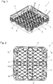
- Fig. 1 shows in a perspective view obliquely from above a washing basket 1 which, as known per se, has a lattice-shaped basket base 2 which, together with the side walls 3, delimits a basket interior 4.
- the support level 7 is a horizontal plane. With the support surfaces 6, the washing rack is thus placed on a generally horizontal plane.
- the contact surfaces 6 thus define the contact plane 7 of the wash basket 1, with which the wash basket 1 in the normal position, ie with the basket base 2 facing down, can be placed on a generally horizontal surface.
- the contact areas 6 can be designed point-like, linear or otherwise. Even with a so-called point-like design, there is ultimately always a certain area available, so that the concept of the contact area 6 is also permissible in this case.
- the side walls 3 can, as also shown in this first exemplary embodiment, be perforated in some areas with openings. In any case, the basket interior 4 is open at the top in the exemplary embodiments shown.
- the wash basket 1 shown here in the first embodiment is primarily for the Designed to wash dishes.
- plate supports 32 known per se are formed on the basket base 2 in this first exemplary embodiment.
- other objects 38 can also be washed with a corresponding wash basket 1 according to the first exemplary embodiment, insofar as this makes sense.
- the plate supports 32 can of course also be omitted.
- Fig. 2 shows a plan view from above of the washing rack 1 according to FIG Fig. 1 .
- the bottom webs 31 of the first exemplary embodiment shown here overall form a diamond-shaped structure.
- the plate supports 32, if present, are advantageously each formed at the intersection points of two bottom webs 31. Of course, all of this does not have to be the case, but is only one of many possible configurations for lattice-shaped basket bases 2 of a washing basket 1 according to the invention.
- Fig. 3 shows a section along the section line A 1 -A 1 for this first exemplary embodiment according to the invention Fig. 2 in a cutting plane which is orthogonal to the plane of the sheet Fig. 2 and thus also stands orthogonally on the contact plane 7 given by the contact surfaces 6.
- Fig. 3 thus shows a view of the inside of the basket 4 onto the inside of one of the side walls 3 of the washing basket 1.
- the curved or multiple angled course of the washing liquid deflecting surface 8 can be seen particularly well.
- the rinsing liquid deflecting surface 8 serves to deflect the rinsing liquid jets 9 penetrating the standing plane 7 from below into the basket interior 4.
- the rinsing liquid deflecting surface 8 extends between an inner wall section 10 of the side wall 3 and an outer wall section 11 of the side wall 3.
- the outer wall section 11 is arranged further outward than the inner wall section 10, as seen from the inner space 4 of the basket Fig. 3 it can be clearly seen that the flushing liquid deflecting surface 8 has deflecting surface regions 13, 14 and 15 which are oriented in different ways.
- corresponding deflecting surface areas 13, 14 and 15 do not always necessarily have to be connected to one another and also do not have to delimit an indentation 28 together with the outer wall section 11.
- Deflection surface areas 13 and 14 arranged according to the invention can, in contrast to the exemplary embodiments shown here, also be configured as stand-alone in the respective side wall 3.
- the rinsing liquid deflecting surface 8 has deflecting surface areas 13 and 14 which, viewed in a cutting plane 16 parallel to the support plane 7, are at an obtuse angle 17 relative to the the inner surface 18 of the inner wall section 10 facing the basket interior 4 are arranged.
- Sections in corresponding cutting planes 16 parallel to the support plane 7 are shown in FIG Figures 7 and 8.
- Figure 7 is a corresponding section along the in Fig. 3 section line E 1 -E 1 .
- the cutting plane 16 parallel to the standing plane 7 runs through the in Fig.
- section line E 1 -E 1 and, like the support plane 7, is orthogonal to the sheet plane of the Fig. 3.
- Fig. 8 shows a corresponding section in a section plane 16 parallel to the support plane 7 through the section line F 1 -F 1 in FIG Fig. 3 .
- the obtuse angle 17 between the inner surface 18 of the inner wall section 10 and the deflecting surface area 13 of the flushing liquid deflecting surface 8 designed according to the invention is shown.
- the obtuse angle 17 is also formed, but not shown separately.
- FIG. 7 and 8 it can be clearly seen that the deflecting surface areas 13 and 14 together with the outer wall section 11 or its inner surface 23 each delimit an indentation 28 which is open in the direction 27 towards the basket interior 4.
- a stiffening web 33 is located in the indentation 28, which can of course also be omitted.
- Fig. 8 illustrates that the deflecting surface areas 13 and 14 designed according to the invention do not necessarily have to be flat in themselves. They can also have a curvature in themselves, as shown in Fig. 8 is easy to see. This does not prevent the obtuse angle 17 from being determined, as shown in FIG Fig. 8 is shown by way of example on the deflecting surface area 14 and the inner wall section 10 adjoining it or its inner surface 18, that is to say pointing towards the basket interior 4.
- these deflecting surface areas 13 and 14, which are arranged in the said parallel sectional plane 16 at an obtuse angle 17 relative to the inner surface of the inner wall section 10, in the in FIG Fig. 3 vertical direction 19 drawn normal to the support plane 7 have a height extension 20 of at least 5mm, preferably of at least 10mm. This height extension 20 is for this embodiment in Fig. 3 drawn.
- the extension 24 drawn in and measured along this deflection surface area 13 should, in preferred embodiments, be at least 5mm, preferably at least 10mm, in order to achieve a corresponding effectiveness in deflecting the rinsing liquid jets 9.
- the extension is measured in the section plane 16 parallel to the standing plane 7 between the inner surface 18 of the inner wall section 10 and the inner surface 23 of the outer wall section 11 directly along the deflecting surface area 13 or 14. If the deflecting surface area 13 or 14 is designed to be curved in this cutting plane 16, measurements are made along this curvature.
- the ones in the Figures 7 and 8 The obtuse angles 17 shown are advantageously in an interval from 91 ° to 160 °, preferably from 95 ° to 140 °.
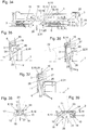
- Figs. 4, 5 and 6 each show sectional planes 21 which are orthogonal to the contact plane 7.
- Fig. 4 shows the section along the in Fig. 3 drawn section line B 1 -B 1
- the orthogonal cutting plane 21 here orthogonally on the support plane 7 and also orthogonally on the plane of the sheet Fig. 3 stands.
- Fig. 5 shows the corresponding section along the section line C 1 -C 1 and Fig. 6 along the section line D 1 -D 1 Fig. 3
- the respective orthogonal cutting planes 21 of the Figures 5 and 6 also orthogonally on the contact plane 7 and also on the sheet plane of the Fig. 3 stand.
- the deflecting surface area 15 of the flushing liquid deflecting surface 8 shown forms the upper end 29 of the indentation 28. In this exemplary embodiment, it is indeed arranged in the orthogonal cutting plane 21 at an acute angle 22 relative to the contact plane 7.
- the deflecting surface area 15 is not designed according to the invention, however, since it does not form an obtuse angle 17 with the inner surface 18 of the adjacent inner wall section 10 in a section plane 16 that is parallel to the support plane 7 and is not shown separately here.
- This first exemplary embodiment thus shows that the washing liquid deflecting surface 8 of washing baskets 1 according to the invention can have both deflecting surface areas 13 and 14 designed according to the invention and deflecting surface areas 15 not designed according to the invention or according to the prior art.
- the deflecting surface areas 13 and 14 according to the invention of the respective flushing liquid deflecting surface 8 formed in a side wall 3 can be present in very different numbers and at very different distances from one another. The design can also be very different.
- the deflecting surface areas 13, 14 and 15 can be connected to one another, but also separated from one another be trained.
- the distance L between the two adjacent indentations 28 formed in a side wall 3 can be formed according to the size of the washing basket 1 and the number of indentations 28 or the deflecting surface areas 13, 14 and can assume very different orders of magnitude.
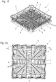
- FIG. 9 shows a second embodiment of a washing basket 1 according to the invention.
- FIG. 9 shows a perspective view from above according to Fig. 9 .
- FIG. 10 shows a plan view of this washing basket 1 of the second embodiment.
- Fig.11 shows a section along the section line A 2 -A 2 in an orthogonal to the plane of the sheet of FIG Fig. 10 standing cutting plane.
- the washing liquid deflecting surface 8 is designed to be smaller overall.
- the second exemplary embodiment there is a larger number of deflecting surface areas 13 and 14 designed according to the invention per side wall 3, the distance L between them and also the vertical extent 20 being smaller than in the first exemplary embodiment.
- a respective deflecting surface area 15 which, viewed in the orthogonal cutting plane 21, encloses an acute angle 22 with the standing plane 7, but, seen in a cutting plane 16 parallel to the standing plane 7, does not have an obtuse angle 17 with the inner surface 18 of the inner wall portion 10.
- Fig. 12 shows a section in the section plane 21 orthogonal to the support plane 7 along the section line B 2 -B 2 from Fig. 11.
- Fig. 13 shows a corresponding section along the section line C 2 -C 2 and Fig. 14 along the section line D 2 -D 2 Fig. 11 .
- the flushing liquid deflecting surface 8 in each case encloses an acute angle 22 with the contact plane 7. This therefore also applies to the deflecting surface areas 13 and 14 embodied according to the invention, as exemplified by the deflecting surface area 14 in FIG Fig. 13 you can see.
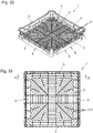
- FIG. 17 again shows a perspective view obliquely from above of the washing basket 1, Fig. 18 a top view.
- the section along the section line A 3 -A 3 is in Fig. 19 shown.
- Fig. 20 shows the section plane 21 orthogonal to the support plane 7 along the section line B 3 -B 3 from Fig. 19, Fig. 21 the corresponding orthogonal cutting plane 21 along the cutting line C 3 -C 3 Figures 19 and 22 the section in the orthogonal section plane 21 along the section line D 3 -D 3 '.
- the configuration according to the invention of the deflecting surface regions 13 and 14 is shown in the sections along the section plane 16 parallel to the support plane 7 in FIG Figures 23 and 24 shown, where Fig. 23 the section along the section line E 3 -E 3 and Fig. 24 the section along the section line F 3 -F 3 in Fig. 19 shows.
- the only difference to the previously mentioned exemplary embodiments according to the invention is that here the rinsing liquid deflecting surface 8 in the view according to FIG Fig. 19 forms a wave-like structure. This does not change the fact that the deflecting surface areas 13 and 14 are designed according to the invention, see Figures 23 and 24 .
- FIG. 25 Show the fourth embodiment of the invention of a washing basket Fig. 25 again a view from diagonally above and Fig. 26 a top view of the washing basket 1.
- the section orthogonal to the support plane 7 along the section line A 4 -A 4 from Fig. 26 is in Fig. 27 shown.
- Fig. 28 shows the section in the section plane 21 orthogonal to the support plane 7 along the section line B 4 -B 4 and Fig. 29 the section in the section plane 21 orthogonal to the support plane 7 along the section line C 4 -C 4 Fig. 27 .
- the inventive design of the deflecting surface areas 13 and 14 is in turn in the Figures 30 and 31 good to see where Fig.
- the deflection surface regions 13 and 14 designed according to the invention form in the view according to FIG Fig. 27 a kind of roof or triangular structure. They touch one another directly at the upper end 29 of the respective indentation 28 without a deflection surface area 15 being arranged between them in this exemplary embodiment. Otherwise, the above statements regarding the other exemplary embodiments according to the invention apply again.
- FIG. 32 to 39 is a fifth embodiment of the invention of a wash basket 1 shown, wherein Fig. 32 again a perspective view obliquely from above and Fig. 33 shows a plan view.
- the section in an orthogonal section plane along section line A 5 -A 5 Fig. 33 is in Fig. 34 shown.
- Fig. 35 shows the section in a section plane 21 orthogonal to the support plane 7 along the section line B 5 -B 5
- Fig. 36 the corresponding section along the section line C 5 -C 5 and Fig. 37 along the section line D 5 -D 5 .
- the inventive design of the deflecting surface areas 13 and 14 is in turn in the Figures 38 and 39 shown.
- FIG. 38 shows the section in a section plane 16 parallel to the support plane 7 along the section line E 5 -E 5 and Fig. 39 the corresponding section along the section line F 5 -F 5 Fig. 34 .
- the deflecting surface areas 13 and 14 form, as in FIG Fig. 34 easy to see, also a roof-shaped structure.
- Fig. 38 shows that the two Deflection surface areas 13 and 14, seen in the cutting plane parallel to the standing plane 7, can also cut in the outer wall section 11 of the washing rack 1.
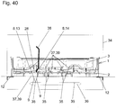
- Fig. 40 shows an example of an arrangement with a dishwasher 34 and a dishwasher basket 1 according to the invention arranged therein, the dishwasher 34 being shown only in a very simplified manner.
- the dishwasher 34 can, as is known per se in the prior art, be designed.
- the dishwasher 34 is located in Fig. 40 a washing basket 1 according to the first embodiment.
- Fig. 40 shows a vertical section in which the cutting plane is orthogonal to the support plane 7. In principle, it is a section along the section line A 1 -A 1 Fig. 2 , the dishwasher 34 also being correspondingly cut here.
- any other washing rack 1 according to the invention and in particular the washing racks 1 according to the exemplary embodiments 2, 3, 4 and 5 shown here can of course also be arranged in the dishwasher 34 in a corresponding manner.
- the washing basket 1 is stored in the in Fig. 40 operating position shown on corresponding rails 12 of the dishwasher 34.
- Fig. 40 the operating position of the washing rack 1 is thus shown in which the washing process in the dishwasher 34 is carried out.
- the washing rack 1 In this operating position or normal position, the washing rack 1 is mounted horizontally in the dishwasher 34, so the support plane 7 of the washing rack 1 is a horizontal plane.
- Fig. 40 schematically shows a plate shown in section as an object 38 to be washed.
- the washing liquid nozzles 35 which in the exemplary embodiment shown here are formed in a rotatably mounted washing arm 36 of the washing machine 34, are located below the basket base 2.
- the washing arm 36 is shown only in abbreviated form, since in this operating position, in which its outer washing liquid nozzles 35 spray washing liquid 39 from below into the side walls 3 of the washing basket 1, viewed spatially from the plane of the drawing Fig. 40 would stand out.
- the rinsing liquid discharge directions 37 of the respective rinsing liquid nozzles 35 are in any case directed towards the basket bottom 2 and also towards the side walls 3, so that the washing liquid 39 in the form of the washing liquid jets 9 during the washing process passes from below, partly through the latticed basket bottom 2, directly into the basket interior 4.
- Another part of the rinsing liquid 39 or rinsing liquid jets 9 is sprayed or injected from below into the indentations 28 in the side walls 3 and then deflected by the rinsing liquid deflecting surface 8 and in particular from deflecting surface areas 13 and 14 designed according to the invention and sprayed or injected into the basket interior 4 .
- Fig. 40 With the aid of two rinsing liquid jets 9 selected by way of example, it is shown how the deflecting surface areas 13 and 14 deflect the rinsing liquid 39 or the rinsing liquid jets 9 in the direction of the object 38 to be washed.
- Fig. 40 shows an example of a method according to the invention for washing objects 38 arranged in the basket interior 4 of a washing basket 1 according to the invention in a dishwasher 34, the washing basket 1 being arranged for washing the objects 38 in the dishwasher 34 via washing liquid nozzles 35 of the dishwasher 34.
- the washing liquid nozzles 35 are located in a rotatably mounted washing arm 36 of the washing machine 34, but this does not necessarily have to be the case.
- the washing liquid 39 is in any case sprayed from the washing liquid nozzles 35 through the side walls 3 and the basket bottom 2 into the basket interior 4, with parts of the washing liquid 39 of the deflecting surface areas 13 and 14 designed according to the invention being deflected into the basket interior 4.
Landscapes
- Washing And Drying Of Tableware (AREA)
- Filters For Electric Vacuum Cleaners (AREA)
- Cleaning By Liquid Or Steam (AREA)
Priority Applications (3)
| Application Number | Priority Date | Filing Date | Title |
|---|---|---|---|
| SI202030026T SI3747338T1 (sl) | 2019-06-03 | 2020-05-07 | Pomivalna košara za pomivalne stroje |
| PL20173387T PL3747338T3 (pl) | 2019-06-03 | 2020-05-07 | Kosz do zmywarek |
| HRP20220071TT HRP20220071T1 (hr) | 2019-06-03 | 2020-05-07 | Košara za pranje kod perilica posuđa |
Applications Claiming Priority (1)
| Application Number | Priority Date | Filing Date | Title |
|---|---|---|---|
| ATA210/2019A AT522074B1 (de) | 2019-06-03 | 2019-06-03 | Spülkorb für Spülmaschinen |
Publications (2)
| Publication Number | Publication Date |
|---|---|
| EP3747338A1 true EP3747338A1 (fr) | 2020-12-09 |
| EP3747338B1 EP3747338B1 (fr) | 2021-11-17 |
Family
ID=70616915
Family Applications (1)
| Application Number | Title | Priority Date | Filing Date |
|---|---|---|---|
| EP20173387.0A Active EP3747338B1 (fr) | 2019-06-03 | 2020-05-07 | Panier pour laves-vaisselles |
Country Status (11)
| Country | Link |
|---|---|
| US (1) | US11589728B2 (fr) |
| EP (1) | EP3747338B1 (fr) |
| AT (1) | AT522074B1 (fr) |
| DK (1) | DK3747338T3 (fr) |
| ES (1) | ES2905798T3 (fr) |
| HR (1) | HRP20220071T1 (fr) |
| HU (1) | HUE057547T2 (fr) |
| LT (1) | LT3747338T (fr) |
| PL (1) | PL3747338T3 (fr) |
| PT (1) | PT3747338T (fr) |
| SI (1) | SI3747338T1 (fr) |
Families Citing this family (4)
| Publication number | Priority date | Publication date | Assignee | Title |
|---|---|---|---|---|
| USD1063279S1 (en) * | 2023-09-15 | 2025-02-18 | Danlin Pan | Bottle drying rack |
| TWD238147S (zh) * | 2024-02-07 | 2025-05-11 | 聯府塑膠股份有限公司 苗栗縣銅鑼鄉銅鑼村自強路18號 (中華民國) | 洗滌籃 |
| USD1114431S1 (en) * | 2024-02-07 | 2026-02-17 | L&F Plastics, Co., Ltd. | Dishwasher basket |
| TWD237533S (zh) * | 2024-02-07 | 2025-04-11 | 聯府塑膠股份有限公司 苗栗縣銅鑼鄉銅鑼村自強路18號 (中華民國) | 洗滌籃之籃體 |
Citations (4)
| Publication number | Priority date | Publication date | Assignee | Title |
|---|---|---|---|---|
| US3584744A (en) * | 1968-10-01 | 1971-06-15 | Ralph Ettlinger Jr | Rack construction for cups and glasses |
| EP1413242A1 (fr) * | 2002-10-25 | 2004-04-28 | FRIES PLANUNGS- UND MARKETINGGESELLSCHAFT m.b.H. | Panier de lave-vaisselle empilable |
| EP1287780B1 (fr) | 2001-08-28 | 2008-10-29 | FRIES PLANUNGS- UND MARKETINGGESELLSCHAFT m.b.H. | Panier pour lave-vaisselle |
| AT12122U1 (de) * | 2010-10-01 | 2011-11-15 | Fries Planung & Marketing | Geschirrkorbeinsatz |
Family Cites Families (10)
| Publication number | Priority date | Publication date | Assignee | Title |
|---|---|---|---|---|
| AT12122B (fr) | 1902-04-24 | 1903-06-10 | Caesar Hasz | |
| US3266632A (en) * | 1964-06-03 | 1966-08-16 | Maslow Louis | Rack |
| US6186328B1 (en) * | 1997-03-31 | 2001-02-13 | Rehrig Pacific Company | Nestable can tray with contoured wall structure |
| DE112004000238C5 (de) * | 2003-02-18 | 2012-05-10 | Lsg Lufthansa Service Holding Ag | Transportkorb |
| AT507308B1 (de) * | 2008-10-01 | 2010-08-15 | Fries Planung & Marketing | Geschirrkorb |
| KR101147471B1 (ko) * | 2011-12-27 | 2012-05-21 | 심홍섭 | 업소용 식기세척기의 밥공기 세척 랙 |
| US9549659B2 (en) * | 2012-07-17 | 2017-01-24 | Ecolab Usa Inc. | Dish rack for oversized containers |
| IT201700012176A1 (it) * | 2017-02-03 | 2018-08-03 | Vi Fer M E Ca S R L | Cestello impilabile per lavastoviglie |
| CN107212829A (zh) * | 2017-06-26 | 2017-09-29 | 茹朝贵 | 一种洗碗清洁装置 |
| AT522471B1 (de) * | 2019-06-03 | 2020-11-15 | Fries Planungs Und Marketinggesellschaft M B H | Spülkorb für Spülmaschinen |
-
2019
- 2019-06-03 AT ATA210/2019A patent/AT522074B1/de not_active IP Right Cessation
-
2020
- 2020-05-07 SI SI202030026T patent/SI3747338T1/sl unknown
- 2020-05-07 LT LTEP20173387.0T patent/LT3747338T/lt unknown
- 2020-05-07 DK DK20173387.0T patent/DK3747338T3/da active
- 2020-05-07 EP EP20173387.0A patent/EP3747338B1/fr active Active
- 2020-05-07 HU HUE20173387A patent/HUE057547T2/hu unknown
- 2020-05-07 ES ES20173387T patent/ES2905798T3/es active Active
- 2020-05-07 HR HRP20220071TT patent/HRP20220071T1/hr unknown
- 2020-05-07 PT PT201733870T patent/PT3747338T/pt unknown
- 2020-05-07 PL PL20173387T patent/PL3747338T3/pl unknown
- 2020-06-03 US US16/891,282 patent/US11589728B2/en active Active
Patent Citations (4)
| Publication number | Priority date | Publication date | Assignee | Title |
|---|---|---|---|---|
| US3584744A (en) * | 1968-10-01 | 1971-06-15 | Ralph Ettlinger Jr | Rack construction for cups and glasses |
| EP1287780B1 (fr) | 2001-08-28 | 2008-10-29 | FRIES PLANUNGS- UND MARKETINGGESELLSCHAFT m.b.H. | Panier pour lave-vaisselle |
| EP1413242A1 (fr) * | 2002-10-25 | 2004-04-28 | FRIES PLANUNGS- UND MARKETINGGESELLSCHAFT m.b.H. | Panier de lave-vaisselle empilable |
| AT12122U1 (de) * | 2010-10-01 | 2011-11-15 | Fries Planung & Marketing | Geschirrkorbeinsatz |
Also Published As
| Publication number | Publication date |
|---|---|
| AT522074B1 (de) | 2020-08-15 |
| HUE057547T2 (hu) | 2022-05-28 |
| PL3747338T3 (pl) | 2022-03-28 |
| DK3747338T3 (da) | 2022-01-31 |
| AT522074A4 (de) | 2020-08-15 |
| LT3747338T (lt) | 2022-02-10 |
| US11589728B2 (en) | 2023-02-28 |
| PT3747338T (pt) | 2021-12-23 |
| SI3747338T1 (sl) | 2022-02-28 |
| ES2905798T3 (es) | 2022-04-12 |
| HRP20220071T1 (hr) | 2022-04-01 |
| EP3747338B1 (fr) | 2021-11-17 |
| US20200375432A1 (en) | 2020-12-03 |
Similar Documents
| Publication | Publication Date | Title |
|---|---|---|
| EP3747338B1 (fr) | Panier pour laves-vaisselles | |
| DE2610379C3 (de) | Geschirrspülmaschine | |
| EP1707100B1 (fr) | Lave-vaisselle à convoyeur et tube de pulvérisation associé | |
| DE4338063C2 (de) | Kastenförmiger Behälter aus Kunststoff | |
| DE102004062243A1 (de) | Geschirrspüler mit Ablenkblenden | |
| EP2271247A1 (fr) | Panier à vaisselle et lave-vaisselle | |
| AT507308B1 (de) | Geschirrkorb | |
| AT522471B1 (de) | Spülkorb für Spülmaschinen | |
| EP1552781A2 (fr) | Lave-vaisselle avec glissières d'extraction du panier. | |
| EP2271248A1 (fr) | Panier à vaisselle et lave-vaisselle | |
| AT410751B (de) | Geschirrkorb für geschirrspülmaschinen | |
| AT522661B1 (de) | Spülkorb für Spülmaschinen | |
| AT12122U1 (de) | Geschirrkorbeinsatz | |
| DE7008981U (de) | Geschirrabtropfstaender. | |
| EP2271246B1 (fr) | Panier à vaisselle et lave-vaisselle | |
| DE102007048198B4 (de) | Korb für eine Geschirrspülmaschine | |
| DE2559621B2 (de) | Abtropffläche einer Spültischabdeckung | |
| DE10056487A1 (de) | Einsatz für einen Geschirrkorb einer Geschirrspülmaschine | |
| EP2312990B1 (fr) | Lave-vaisselle | |
| DE19727537C1 (de) | Waschmaschine für Vertikallamellen | |
| DE19820979A1 (de) | Geschirrspülmaschine mit einer Besteckablage | |
| EP2883488B1 (fr) | Récipient de rinçage avec porte-vaisselle | |
| EP2262407B1 (fr) | Panier à vaisselle et lave-vaisselle | |
| DE102024208439A1 (de) | Spülgutaufnahme mit Anlagegeometrie zum versetzten Einstellen von Geschirrteilen | |
| DE8908813U1 (de) | Stapelbarer Transport- und Lagerkasten aus Metall und/oder Kunststoff |
Legal Events
| Date | Code | Title | Description |
|---|---|---|---|
| REG | Reference to a national code |
Ref country code: HR Ref legal event code: TUEP Ref document number: P20220071 Country of ref document: HR |
|
| PUAI | Public reference made under article 153(3) epc to a published international application that has entered the european phase |
Free format text: ORIGINAL CODE: 0009012 |
|
| STAA | Information on the status of an ep patent application or granted ep patent |
Free format text: STATUS: THE APPLICATION HAS BEEN PUBLISHED |
|
| AK | Designated contracting states |
Kind code of ref document: A1 Designated state(s): AL AT BE BG CH CY CZ DE DK EE ES FI FR GB GR HR HU IE IS IT LI LT LU LV MC MK MT NL NO PL PT RO RS SE SI SK SM TR |
|
| AX | Request for extension of the european patent |
Extension state: BA ME |
|
| STAA | Information on the status of an ep patent application or granted ep patent |
Free format text: STATUS: REQUEST FOR EXAMINATION WAS MADE |
|
| 17P | Request for examination filed |
Effective date: 20210118 |
|
| RBV | Designated contracting states (corrected) |
Designated state(s): AL AT BE BG CH CY CZ DE DK EE ES FI FR GB GR HR HU IE IS IT LI LT LU LV MC MK MT NL NO PL PT RO RS SE SI SK SM TR |
|
| STAA | Information on the status of an ep patent application or granted ep patent |
Free format text: STATUS: EXAMINATION IS IN PROGRESS |
|
| 17Q | First examination report despatched |
Effective date: 20210527 |
|
| GRAP | Despatch of communication of intention to grant a patent |
Free format text: ORIGINAL CODE: EPIDOSNIGR1 |
|
| STAA | Information on the status of an ep patent application or granted ep patent |
Free format text: STATUS: GRANT OF PATENT IS INTENDED |
|
| INTG | Intention to grant announced |
Effective date: 20210811 |
|
| GRAS | Grant fee paid |
Free format text: ORIGINAL CODE: EPIDOSNIGR3 |
|
| GRAA | (expected) grant |
Free format text: ORIGINAL CODE: 0009210 |
|
| STAA | Information on the status of an ep patent application or granted ep patent |
Free format text: STATUS: THE PATENT HAS BEEN GRANTED |
|
| AK | Designated contracting states |
Kind code of ref document: B1 Designated state(s): AL AT BE BG CH CY CZ DE DK EE ES FI FR GB GR HR HU IE IS IT LI LT LU LV MC MK MT NL NO PL PT RO RS SE SI SK SM TR |
|
| REG | Reference to a national code |
Ref country code: GB Ref legal event code: FG4D Free format text: NOT ENGLISH |
|
| REG | Reference to a national code |
Ref country code: IE Ref legal event code: FG4D Free format text: LANGUAGE OF EP DOCUMENT: GERMAN |
|
| REG | Reference to a national code |
Ref country code: DE Ref legal event code: R096 Ref document number: 502020000351 Country of ref document: DE |
|
| REG | Reference to a national code |
Ref country code: AT Ref legal event code: REF Ref document number: 1447379 Country of ref document: AT Kind code of ref document: T Effective date: 20211215 |
|
| REG | Reference to a national code |
Ref country code: PT Ref legal event code: SC4A Ref document number: 3747338 Country of ref document: PT Date of ref document: 20211223 Kind code of ref document: T Free format text: AVAILABILITY OF NATIONAL TRANSLATION Effective date: 20211215 |
|
| REG | Reference to a national code |
Ref country code: FI Ref legal event code: FGE |
|
| REG | Reference to a national code |
Ref country code: DK Ref legal event code: T3 Effective date: 20220126 |
|
| REG | Reference to a national code |
Ref country code: SE Ref legal event code: TRGR |
|
| REG | Reference to a national code |
Ref country code: NL Ref legal event code: FP |
|
| REG | Reference to a national code |
Ref country code: EE Ref legal event code: FG4A Ref document number: E021732 Country of ref document: EE Effective date: 20211220 |
|
| REG | Reference to a national code |
Ref country code: GR Ref legal event code: EP Ref document number: 20220400319 Country of ref document: GR Effective date: 20220309 |
|
| REG | Reference to a national code |
Ref country code: NO Ref legal event code: T2 Effective date: 20211117 |
|
| REG | Reference to a national code |
Ref country code: HR Ref legal event code: T1PR Ref document number: P20220071 Country of ref document: HR |
|
| REG | Reference to a national code |
Ref country code: ES Ref legal event code: FG2A Ref document number: 2905798 Country of ref document: ES Kind code of ref document: T3 Effective date: 20220412 |
|
| PG25 | Lapsed in a contracting state [announced via postgrant information from national office to epo] |
Ref country code: RS Free format text: LAPSE BECAUSE OF FAILURE TO SUBMIT A TRANSLATION OF THE DESCRIPTION OR TO PAY THE FEE WITHIN THE PRESCRIBED TIME-LIMIT Effective date: 20211117 Ref country code: BG Free format text: LAPSE BECAUSE OF FAILURE TO SUBMIT A TRANSLATION OF THE DESCRIPTION OR TO PAY THE FEE WITHIN THE PRESCRIBED TIME-LIMIT Effective date: 20220217 |
|
| REG | Reference to a national code |
Ref country code: SK Ref legal event code: T3 Ref document number: E 39201 Country of ref document: SK |
|
| REG | Reference to a national code |
Ref country code: HU Ref legal event code: AG4A Ref document number: E057547 Country of ref document: HU |
|
| PG25 | Lapsed in a contracting state [announced via postgrant information from national office to epo] |
Ref country code: IS Free format text: LAPSE BECAUSE OF FAILURE TO SUBMIT A TRANSLATION OF THE DESCRIPTION OR TO PAY THE FEE WITHIN THE PRESCRIBED TIME-LIMIT Effective date: 20220317 |
|
| REG | Reference to a national code |
Ref country code: HR Ref legal event code: ODRP Ref document number: P20220071 Country of ref document: HR Payment date: 20220419 Year of fee payment: 3 |
|
| PG25 | Lapsed in a contracting state [announced via postgrant information from national office to epo] |
Ref country code: SM Free format text: LAPSE BECAUSE OF FAILURE TO SUBMIT A TRANSLATION OF THE DESCRIPTION OR TO PAY THE FEE WITHIN THE PRESCRIBED TIME-LIMIT Effective date: 20211117 Ref country code: RO Free format text: LAPSE BECAUSE OF FAILURE TO SUBMIT A TRANSLATION OF THE DESCRIPTION OR TO PAY THE FEE WITHIN THE PRESCRIBED TIME-LIMIT Effective date: 20211117 |
|
| REG | Reference to a national code |
Ref country code: DE Ref legal event code: R097 Ref document number: 502020000351 Country of ref document: DE |
|
| PLBE | No opposition filed within time limit |
Free format text: ORIGINAL CODE: 0009261 |
|
| STAA | Information on the status of an ep patent application or granted ep patent |
Free format text: STATUS: NO OPPOSITION FILED WITHIN TIME LIMIT |
|
| 26N | No opposition filed |
Effective date: 20220818 |
|
| PG25 | Lapsed in a contracting state [announced via postgrant information from national office to epo] |
Ref country code: AL Free format text: LAPSE BECAUSE OF FAILURE TO SUBMIT A TRANSLATION OF THE DESCRIPTION OR TO PAY THE FEE WITHIN THE PRESCRIBED TIME-LIMIT Effective date: 20211117 |
|
| PG25 | Lapsed in a contracting state [announced via postgrant information from national office to epo] |
Ref country code: MC Free format text: LAPSE BECAUSE OF FAILURE TO SUBMIT A TRANSLATION OF THE DESCRIPTION OR TO PAY THE FEE WITHIN THE PRESCRIBED TIME-LIMIT Effective date: 20211117 Ref country code: LU Free format text: LAPSE BECAUSE OF NON-PAYMENT OF DUE FEES Effective date: 20220507 |
|
| REG | Reference to a national code |
Ref country code: HR Ref legal event code: ODRP Ref document number: P20220071 Country of ref document: HR Payment date: 20230418 Year of fee payment: 4 |
|
| PG25 | Lapsed in a contracting state [announced via postgrant information from national office to epo] |
Ref country code: MK Free format text: LAPSE BECAUSE OF FAILURE TO SUBMIT A TRANSLATION OF THE DESCRIPTION OR TO PAY THE FEE WITHIN THE PRESCRIBED TIME-LIMIT Effective date: 20211117 Ref country code: CY Free format text: LAPSE BECAUSE OF FAILURE TO SUBMIT A TRANSLATION OF THE DESCRIPTION OR TO PAY THE FEE WITHIN THE PRESCRIBED TIME-LIMIT Effective date: 20211117 |
|
| REG | Reference to a national code |
Ref country code: HR Ref legal event code: ODRP Ref document number: P20220071 Country of ref document: HR Payment date: 20240419 Year of fee payment: 5 |
|
| PG25 | Lapsed in a contracting state [announced via postgrant information from national office to epo] |
Ref country code: MT Free format text: LAPSE BECAUSE OF FAILURE TO SUBMIT A TRANSLATION OF THE DESCRIPTION OR TO PAY THE FEE WITHIN THE PRESCRIBED TIME-LIMIT Effective date: 20211117 |
|
| REG | Reference to a national code |
Ref country code: HR Ref legal event code: ODRP Ref document number: P20220071 Country of ref document: HR Payment date: 20250416 Year of fee payment: 6 |
|
| PG25 | Lapsed in a contracting state [announced via postgrant information from national office to epo] |
Ref country code: TR Free format text: LAPSE BECAUSE OF FAILURE TO SUBMIT A TRANSLATION OF THE DESCRIPTION OR TO PAY THE FEE WITHIN THE PRESCRIBED TIME-LIMIT Effective date: 20211117 |
|
| REG | Reference to a national code |
Ref country code: HR Ref legal event code: ODRP Ref document number: P20220071 Country of ref document: HR Payment date: 20260420 Year of fee payment: 7 |
|
| REG | Reference to a national code |
Ref country code: CH Ref legal event code: U11 Free format text: ST27 STATUS EVENT CODE: U-0-0-U10-U11 (AS PROVIDED BY THE NATIONAL OFFICE) Effective date: 20260601 |
|
| PGFP | Annual fee paid to national office [announced via postgrant information from national office to epo] |
Ref country code: NL Payment date: 20260519 Year of fee payment: 7 |
|
| PGFP | Annual fee paid to national office [announced via postgrant information from national office to epo] |
Ref country code: HU Payment date: 20260507 Year of fee payment: 7 |
|
| PGFP | Annual fee paid to national office [announced via postgrant information from national office to epo] |
Ref country code: ES Payment date: 20260609 Year of fee payment: 7 |
|
| PGFP | Annual fee paid to national office [announced via postgrant information from national office to epo] |
Ref country code: GB Payment date: 20260513 Year of fee payment: 7 Ref country code: DK Payment date: 20260520 Year of fee payment: 7 Ref country code: PL Payment date: 20260417 Year of fee payment: 7 |
|
| PGFP | Annual fee paid to national office [announced via postgrant information from national office to epo] |
Ref country code: GR Payment date: 20260521 Year of fee payment: 7 Ref country code: IT Payment date: 20260522 Year of fee payment: 7 |
|
| PGFP | Annual fee paid to national office [announced via postgrant information from national office to epo] |
Ref country code: DE Payment date: 20260522 Year of fee payment: 7 Ref country code: LT Payment date: 20260417 Year of fee payment: 7 |
|
| PGFP | Annual fee paid to national office [announced via postgrant information from national office to epo] |
Ref country code: NO Payment date: 20260519 Year of fee payment: 7 |
|
| PGFP | Annual fee paid to national office [announced via postgrant information from national office to epo] |
Ref country code: AT Payment date: 20260507 Year of fee payment: 7 Ref country code: SE Payment date: 20260520 Year of fee payment: 7 Ref country code: FI Payment date: 20260519 Year of fee payment: 7 |
|
| PGFP | Annual fee paid to national office [announced via postgrant information from national office to epo] |
Ref country code: CH Payment date: 20260601 Year of fee payment: 7 Ref country code: IE Payment date: 20260519 Year of fee payment: 7 Ref country code: BE Payment date: 20260518 Year of fee payment: 7 |
|
| PGFP | Annual fee paid to national office [announced via postgrant information from national office to epo] |
Ref country code: HR Payment date: 20260420 Year of fee payment: 7 Ref country code: EE Payment date: 20260527 Year of fee payment: 7 |
|
| PGFP | Annual fee paid to national office [announced via postgrant information from national office to epo] |
Ref country code: PT Payment date: 20260420 Year of fee payment: 7 |
|
| PGFP | Annual fee paid to national office [announced via postgrant information from national office to epo] |
Ref country code: CZ Payment date: 20260428 Year of fee payment: 7 |
|
| PGFP | Annual fee paid to national office [announced via postgrant information from national office to epo] |
Ref country code: FR Payment date: 20260521 Year of fee payment: 7 |
|
| PGFP | Annual fee paid to national office [announced via postgrant information from national office to epo] |
Ref country code: LV Payment date: 20260521 Year of fee payment: 7 |
|
| PGFP | Annual fee paid to national office [announced via postgrant information from national office to epo] |
Ref country code: SK Payment date: 20260420 Year of fee payment: 7 |
|
| PGFP | Annual fee paid to national office [announced via postgrant information from national office to epo] |
Ref country code: SI Payment date: 20260417 Year of fee payment: 7 |