EP1552936B1 - Réservoir purgeable pour une tête d'impression - Google Patents
Réservoir purgeable pour une tête d'impression Download PDFInfo
- Publication number
- EP1552936B1 EP1552936B1 EP05000078A EP05000078A EP1552936B1 EP 1552936 B1 EP1552936 B1 EP 1552936B1 EP 05000078 A EP05000078 A EP 05000078A EP 05000078 A EP05000078 A EP 05000078A EP 1552936 B1 EP1552936 B1 EP 1552936B1
- Authority
- EP
- European Patent Office
- Prior art keywords
- ink
- plate
- channel
- reservoir
- print head
- Prior art date
- Legal status (The legal status is an assumption and is not a legal conclusion. Google has not performed a legal analysis and makes no representation as to the accuracy of the status listed.)
- Ceased
Links
- 238000010926 purge Methods 0.000 description 9
- 239000007788 liquid Substances 0.000 description 4
- 239000007787 solid Substances 0.000 description 4
- 238000011144 upstream manufacturing Methods 0.000 description 3
- 239000012535 impurity Substances 0.000 description 2
- 230000037361 pathway Effects 0.000 description 2
- 239000003086 colorant Substances 0.000 description 1
- 230000001419 dependent effect Effects 0.000 description 1
- 238000001914 filtration Methods 0.000 description 1
- 239000000463 material Substances 0.000 description 1
- 238000000034 method Methods 0.000 description 1
- 239000000758 substrate Substances 0.000 description 1
Images


Classifications
-
- B—PERFORMING OPERATIONS; TRANSPORTING
- B41—PRINTING; LINING MACHINES; TYPEWRITERS; STAMPS
- B41J—TYPEWRITERS; SELECTIVE PRINTING MECHANISMS, i.e. MECHANISMS PRINTING OTHERWISE THAN FROM A FORME; CORRECTION OF TYPOGRAPHICAL ERRORS
- B41J2/00—Typewriters or selective printing mechanisms characterised by the printing or marking process for which they are designed
- B41J2/005—Typewriters or selective printing mechanisms characterised by the printing or marking process for which they are designed characterised by bringing liquid or particles selectively into contact with a printing material
- B41J2/01—Ink jet
- B41J2/17—Ink jet characterised by ink handling
- B41J2/19—Ink jet characterised by ink handling for removing air bubbles
-
- B—PERFORMING OPERATIONS; TRANSPORTING
- B41—PRINTING; LINING MACHINES; TYPEWRITERS; STAMPS
- B41J—TYPEWRITERS; SELECTIVE PRINTING MECHANISMS, i.e. MECHANISMS PRINTING OTHERWISE THAN FROM A FORME; CORRECTION OF TYPOGRAPHICAL ERRORS
- B41J2/00—Typewriters or selective printing mechanisms characterised by the printing or marking process for which they are designed
- B41J2/005—Typewriters or selective printing mechanisms characterised by the printing or marking process for which they are designed characterised by bringing liquid or particles selectively into contact with a printing material
- B41J2/01—Ink jet
- B41J2/17—Ink jet characterised by ink handling
- B41J2/175—Ink supply systems ; Circuit parts therefor
- B41J2/17503—Ink cartridges
- B41J2/1752—Mounting within the printer
-
- B—PERFORMING OPERATIONS; TRANSPORTING
- B41—PRINTING; LINING MACHINES; TYPEWRITERS; STAMPS
- B41J—TYPEWRITERS; SELECTIVE PRINTING MECHANISMS, i.e. MECHANISMS PRINTING OTHERWISE THAN FROM A FORME; CORRECTION OF TYPOGRAPHICAL ERRORS
- B41J2/00—Typewriters or selective printing mechanisms characterised by the printing or marking process for which they are designed
- B41J2/005—Typewriters or selective printing mechanisms characterised by the printing or marking process for which they are designed characterised by bringing liquid or particles selectively into contact with a printing material
- B41J2/01—Ink jet
- B41J2/17—Ink jet characterised by ink handling
- B41J2/175—Ink supply systems ; Circuit parts therefor
- B41J2/17593—Supplying ink in a solid state
-
- B—PERFORMING OPERATIONS; TRANSPORTING
- B41—PRINTING; LINING MACHINES; TYPEWRITERS; STAMPS
- B41J—TYPEWRITERS; SELECTIVE PRINTING MECHANISMS, i.e. MECHANISMS PRINTING OTHERWISE THAN FROM A FORME; CORRECTION OF TYPOGRAPHICAL ERRORS
- B41J25/00—Actions or mechanisms not otherwise provided for
- B41J25/304—Bodily-movable mechanisms for print heads or carriages movable towards or from paper surface
Definitions
- Ink jet printers create an image on a surface by ejecting ink through orifices in a print head face plate onto a substrate.
- the print head face plate communicates with a print head reservoir, which communicates with an ink source.
- Solid ink printers melt solid ink and deliver the melted ink to the print head reservoir.
- the ink that remains in the print head reservoir can freeze.
- air that was once in solution in the ink can come out of solution to form air bubbles or air pockets in the print head reservoir.
- Air pockets can impede the filtering of the ink as it travels toward the orifices in the print head face plate. Air pockets can also impair the print quality of the printer when an air bubble, as opposed to ink, is delivered through the orifice resulting in an unintended blank spot on the print media. Accordingly, it is desirable to purge periodically the cavities and channels in the print head reservoir to increase print quality.
- a vacuum system is costly, time consuming and less efficient than a system that uses positive pressure. Furthermore, it is desirable to wipe the jets during purging, which is not possible when using a vacuum system. Accordingly, a positive pressure purge system is desirable. In a positive pressure purge system it is desirable to purge the print head using as little ink as possible.
- JP04235057A Patent Abstract of Japan describes ink jet printhead.
- the device includes the features as recited in the preamble of claim 1.
- FIGURE 1 is a front perspective view of a print head reservoir for an ink jet printer.
- FIGURE 2 is a front perspective view of a rear plate of the print head reservoir of FIGURE 1 .
- FIGURE 3 is a view of a side cross-section of the print head reservoir of FIGURE 1 .
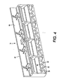
- FIGURE 4 is a rear perspective view of a middle plate of the print head reservoir of FIGURE 1 .
- FIGURE 5 is a close up view of an inlet of the middle plate of FIGURE 4 .
- FIGURE 6 is an elevation view of the front side of the middle plate of FIGURE 4 .
- FIGURE 7 is a close up cross section of the upper portion of the print head reservoir of FIGURE 1 .
- FIGURE 8 is an elevation view of the rear side of a front plate of the print head reservoir of FIGURE 1 .
- FIGURE 9 is an elevation view of the front side of the front plate of FIGURE 8 .
- FIGURE 10 is a front elevation view of the print head reservoir of FIGURE 1 including a fourth plate attached to the front side of the front plate.
- FIGURE 11 is a perspective view of an ink jet printer that contains the print head reservoir of FIGURE 1 .
- FIGURE 12 is a cross-sectional view of the ink jet printer of FIGURE 11 .
- a print head A for an ink jet printer B generally delivers liquid ink to a jet stack C that transfers the ink onto a drum D.
- the print media which can include paper, travels around the drum and picks up the ink deposited on the drum. Air can get into the pathway of the ink as it travels through the print head. To remove the air from the pathway, the print head reservoir is purged, which will be described in more detail below.
- a print head reservoir 10 includes a first or front plate 12, a second or middle plate 14 and a third or rear plate 16.
- the print head reservoir 10 is a portion of the print head and is situated inside the ink jet printer such that the bottom of each plate is substantially horizontal and the reservoir can rotate about a pair of journals 18 (only one visible in FIGURE 1 ).
- the terms "front,” “middle,” and “rear” are used for ease of understanding to describe the components of the reservoir as they are shown in the figures; the terms are not used to limit the position of components in relation to one another.
- the ink travels from the rear plate 16 towards the front plate 12.
- the rear plate includes a front side 20 that is adjacent the middle plate 14 when the reservoir is assembled and a rear side 22 opposite the front side.
- a plurality of bucket walls 24 extend from the rear side 22 to define a plurality of ink buckets 26.
- each bucket receives a different color ink, particularly yellow, cyan, magenta and black; however, a fewer or greater number of ink buckets can be provided and the ink buckets can receive different colors of ink.
- the ink buckets 26 usually receive ink that has been melted and dripped into the buckets; however, liquid ink that has not been melted can also be delivered to the ink buckets.
- each ink bucket 26 communicates with a passage 28 which communicates with a rear plate outlet 32.
- a filter 34 is disposed in each ink bucket on a shoulder 36 that projects inwardly from the bucket wall 24 into the ink bucket 26.
- the filter 34 removes any impurities in the ink before the ink travels into the passage 28 and towards the rear plate outlet 32.
- the rear plate outlet 32 communicates with a middle plate inlet 40 through a valve member 42.
- the valve member 42 comprises a component of a one-way check valve that allows ink to pass from the rear plate outlet 32 into the middle plate inlet 40.
- the valve member 42 precludes ink from passing from the middle plate inlet 40 back into the rear plate outlet 32.
- the valve member 42 opens and closes in response to a pressure differential between the rear plate outlet 32 and the middle plate inlet 40.
- the middle plate 14 includes a front side 44 and a rear side 46.
- the front side 44 of the middle plate abuts the front plate 12 and the rear side 46 of the middle plate abuts the front side 20 of the rear plate 16.
- the middle plate inlet 40 includes three lobes situated 120 degrees apart from one another formed in the rear side 46 of the middle plate 16.
- Two lobes 52 depend generally downward and the third lobe 50 extends upward to communicate with an ink chamber 56.
- Each downward depending lobe 52 includes an opening 58 that communicates with a passage 64 (only one shown in phantom in FIGURE 3 ) which communicates with a middle plate outlet 68 on the front side 44 of the middle plate 14.
- eight middle plate outlets 68 are provided at the bottom of the front side 44 of the middle plate, two for each color of ink. A greater or fewer number of middle plate outlets can be provided.
- ink flows into the middle plate inlet 40 and into the ink chamber 56 through the upward lobe 50. Ink exits the ink chamber through openings 58 ( FIGURE 5 ) in the downward lobes 52.
- the ink chamber 56 is defined as a depression in both the rear side 46 of the middle plate 14 and the front side 20 of the rear plate 16, as seen in FIGURE 3 . Ink exits the middle plate outlets 68, which are in communication with the passages 64 (only one shown), and enters an upstream filter cavity 74.
- a vertical filter 76 is sandwiched between and situated substantially parallel to the front plate 12 and the middle plate 14.
- the upstream filter cavity 74 is defined between the front side 44 of the middle plate 14 and the filter 76.
- the filter 76 includes two layers, a first layer 78 made of a fine screen and a second layer 82 made of a felt material. Each of the filters can remove impurities as small as 10 microns from the ink. Ink flows through the filter 76 from the upstream filter cavity 74 into a downstream filter cavity 86, which will be described in more detail below.
- the front plate 12 includes a front side 90 ( FIGURE 9 ) and a rear side 92 ( FIGURE 8 ), which is adjacent the filter 76.
- the downstream filter cavity 86 is defined between the filter 76 and the rear side 92 of the front plate 12.
- the front plate 12 includes a plurality of openings 94 on the rear side 92 that communicate through passages with a plurality of front plate outlets 96 ( FIGURE 9 ) on the front side 90 of the front plate.
- the openings and front plate outlets will be described as having a certain color ink flowing through them.
- the rear side 92 of the front plate 12 includes four depressions that define four downstream filter cavities 86.
- the downstream cavities will be referred to as 86B, 86M, 86C and 86Y, where the letter refers to the color of ink (black, magenta, cyan and yellow) in the downstream cavity.
- some downstream filter cavities have more than one opening 94, thus on the front side 90 of the front plate 12 more than one plate outlet 96 can be provided for a particular color.
- the black downstream filter cavity 86B has one opening 94B
- the magenta downstream filter cavity 86M has three openings 94M
- the cyan downstream filter cavity 86C has two openings 94C
- the yellow downstream filter cavity 86Y has one opening 94Y.
- Each of these openings 94 communicates with a corresponding front plate outlet 96 ( FIGURE 9 ) through a passage.
- the front side 90 of the front plate 12 includes a plurality of angled channels 98 formed in the plate.
- Each front plate outlet 96 is disposed in an angled channel.
- the channels 98 deliver ink laterally across the front plate 12 to a plurality of corresponding outlet regions 102, where the ink can pass through a fourth plate 100 ( FIGURE 10 ) en route to the jet stack (not shown).
- each color has four outlet regions 102 equally spaced laterally along the front plate.
- the channels and the outlet regions will be referred to with a suffix following the reference numeral that corresponds to the color of ink that travels through the channel toward the outlet region.
- channel 98Y receives yellow ink from front plate outlet 96Y and delivers the yellow ink to four outlet regions 102Y evenly spaced laterally along and near the top of the front side 90 of the front plate 12.
- Channel 98B receives black ink from front plate outlet 96B and delivers black ink to four outlet regions 102B situated next to the yellow outlet regions 102Y.
- To deliver black ink to three of the outlet regions 102B would require the black ink channel 98B to cross over the yellow ink channel.
- channel openings 104B are provided at the apex of angled portions of the black channel 98B.
- the channel openings 104B communicate through a passage to corresponding underpass inlets 106B in the rear side 92 of the front panel 12 ( FIGURE 8 ).
- the underpass inlets 106B communicate with corresponding underpass channels 108B formed on the rear side 92.
- the underpass channels lead to underpass outlets 112B which communicate through a passage with a corresponding outlet region 102B on the front side 90 of the front plate 12 ( FIGURE 9 ). This is also shown in cross-section in FIGURE 7 .
- the underpass channels 108B are formed as depressions in both the rear side 92 of the front plate 12 and the front side 44 of the middle plate 14.
- two separate channels 98C are provided to carry cyan ink towards four outlet regions 102C evenly spaced laterally along and near the bottom of the front plate 12.
- the left most first plate outlet 96C communicates with the left channel 98C to deliver cyan ink to the two left outlet regions 102C.
- the left channel also includes a channel opening 104C, similar to the channel opening described above.
- the channel opening 104C communicates through a passage to a corresponding underpass inlet 106C ( FIGURE 8 ) in the rear side 92 of the front panel 12.
- the underpass inlet 106C communicates with a corresponding underpass channel 108C formed on the rear side 92.
- the underpass channel 108C leads to an underpass outlet 112C which communicates through a passage with a corresponding left most outlet region 102C (as shown in FIGURE 9 ) on the front side 90 of the front plate 12.
- the cyan underpass channel 108C is also defined on the front side 44 of the middle plate 14.
- Three channels 98M in communication with three magenta front plate outlets 96M carry magenta ink towards four outlet regions 102M. Each magenta outlet region 102M is situated next to a corresponding cyan outlet region 102C.
- melted ink travels through the printer reservoir 10.
- the ink can freeze in the printer reservoir. During the freeze process, air comes out of solution that was previously dissolved in the liquid ink.
- the printer is turned back on and the printer reservoir is warmed up, the air that has come out of solution is left as bubbles in the liquid ink.
- One area of the printer reservoir 10 where the air bubbles can form is in the channels 98 on the front side 92 of the first plate 12.
- the channels are angled or sloped towards the outlet regions 102 to encourage the air bubbles to passively move toward the outlet regions through buoyancy of the air bubble.
- the outlet regions 102 are located at the apex of angled portions of the channels 98.
- the ink can be passed through the channels at a greater pressure during a purge cycle by, for example, forcing air into the ink chambers 56 by way of an air pressure source, which is in communication with the channels 98.
- the particular angle or slope of the channel is determined such that large bubbles generate enough unconstrained buoyancy to overcome the surface tension holding them in position.
Landscapes
- Ink Jet (AREA)
Claims (7)
- Réservoir pour tête d'impression comprenant:une plaque (12) ayant un premier et un deuxième côtés (90, 92) et un passage (96) s'étendant à travers ladite plaque (12), ladite plaque définissant un canal (98), ledit canal ayant une section transversale et une longueur substantiellement perpendiculaire à ladite section transversale, ledit canal (98) ayant des portions en pente adjacentes s'étendant le long de ladite longueur du canal et étant inclinées vers une région de refoulement (102), ledit canal (98) en communication avec le passage (96) et la région de refoulement (102) située à proximité d'une intersection d'au moins deux portions en pente adjacentes du canal (98),caractérisé en ce que
la région de refoulement (102) est configurée pour faire passer de l'encre à un empilement à jets; et
les portions en pente étant inclinées de manière à ce que, lorsque le réservoir pour tête d'impression est utilisé dans une imprimante, les portions en pente soient inclinées par rapport à l'horizontale vers le haut vers l'intersection d'au moins deux portions en pente adjacentes de sorte que la région de refoulement (102) soit à une position plus élevée qu'une section quelconque des portions en pente. - Réservoir de la revendication 1, comprenant en plus un compartiment à encre (26) en communication avec le passage (96).
- Réservoir de la revendication 2, comprenant en plus un filtre (76) interposé entre le canal (98) et ledit compartiment à encre (26), où ledit filtre est situé substantiellement parallèlement à ladite plaque (12).
- Réservoir de la revendication 3, comprenant en plus une plaque additionnelle (14), où ledit filtre (76) est intercalé entre ladite plaque (12) qui définit le canal (98) et ladite plaque additionnelle (14).
- Réservoir de la revendication 1, où le canal (98) est adapté pour porter une première couleur d'encre, le réservoir comprenant en plus un canal additionnel (108) formé dans ladite plaque (12) et passant sous le canal (98) adapté pour porter la première couleur d'encre dans la direction d'épaisseur de plaque.
- Réservoir de la revendication 5, où le canal (98) adapté pour porter la première couleur d'encre est formé sur le premier côté (90) de ladite plaque (12) et le canal additionnel (108) inclut au moins une portion formée sur le deuxième côté (92) de ladite plaque (12).
- Réservoir de la revendication 5, où le canal additionnel (108) est adapté pour porter une deuxième couleur d'encre.
Applications Claiming Priority (2)
| Application Number | Priority Date | Filing Date | Title |
|---|---|---|---|
| US752950 | 1985-07-08 | ||
| US10/752,950 US7144100B2 (en) | 2004-01-07 | 2004-01-07 | Purgeable print head reservoir |
Publications (2)
| Publication Number | Publication Date |
|---|---|
| EP1552936A1 EP1552936A1 (fr) | 2005-07-13 |
| EP1552936B1 true EP1552936B1 (fr) | 2008-04-02 |
Family
ID=34592566
Family Applications (1)
| Application Number | Title | Priority Date | Filing Date |
|---|---|---|---|
| EP05000078A Ceased EP1552936B1 (fr) | 2004-01-07 | 2005-01-04 | Réservoir purgeable pour une tête d'impression |
Country Status (4)
| Country | Link |
|---|---|
| US (1) | US7144100B2 (fr) |
| EP (1) | EP1552936B1 (fr) |
| JP (1) | JP4828830B2 (fr) |
| DE (1) | DE602005005723T2 (fr) |
Families Citing this family (14)
| Publication number | Priority date | Publication date | Assignee | Title |
|---|---|---|---|---|
| USD547370S1 (en) * | 2005-11-18 | 2007-07-24 | Brother Industries, Ltd. | Frame of ink cartridge |
| USD542344S1 (en) * | 2006-05-01 | 2007-05-08 | Fujifilm/Dimatix Inc. | Printhead |
| US7682008B2 (en) * | 2006-12-05 | 2010-03-23 | Xerox Corporation | Printhead reservoir with siphon vents |
| US7992986B2 (en) * | 2008-03-17 | 2011-08-09 | Xerox Corporation | Method for increasing printhead reliability |
| US7762656B2 (en) * | 2008-03-26 | 2010-07-27 | Xerox Corporation | Method for preventing nozzle contamination during warm-up |
| US7883198B2 (en) * | 2008-05-01 | 2011-02-08 | Xerox Corporation | Rapid response one-way valve for high speed solid ink delivery |
| US8079691B2 (en) * | 2009-02-09 | 2011-12-20 | Xerox Corporation | Foam plate for reducing foam in a printhead |
| US8454144B2 (en) * | 2010-01-08 | 2013-06-04 | Xerox Corporation | Ink storage reservoir for a solid ink printhead |
| US8419157B2 (en) * | 2010-02-26 | 2013-04-16 | Palo Alto Research Center Incorporated | Apparatus for controlled freezing of melted solid ink in a solid ink printer |
| US8562117B2 (en) | 2011-02-07 | 2013-10-22 | Palo Alto Research Center Incorporated | Pressure pulses to reduce bubbles and voids in phase change ink |
| US8556372B2 (en) | 2011-02-07 | 2013-10-15 | Palo Alto Research Center Incorporated | Cooling rate and thermal gradient control to reduce bubbles and voids in phase change ink |
| US8506063B2 (en) | 2011-02-07 | 2013-08-13 | Palo Alto Research Center Incorporated | Coordination of pressure and temperature during ink phase change |
| US9272525B2 (en) | 2013-09-11 | 2016-03-01 | Xerox Corporation | System and method for controlling air bubble formation in solid inkjet printer ink flow paths |
| US9168752B2 (en) * | 2013-10-18 | 2015-10-27 | Hewlett-Packard Development Company, L.P. | Print head priming systems |
Family Cites Families (15)
| Publication number | Priority date | Publication date | Assignee | Title |
|---|---|---|---|---|
| DE3204662C2 (de) | 1982-02-10 | 1984-03-08 | Siemens AG, 1000 Berlin und 8000 München | Schreibwerk eines nach dem Unterdruckverfahren arbeitenden Tintenschreibers |
| US5087930A (en) * | 1989-11-01 | 1992-02-11 | Tektronix, Inc. | Drop-on-demand ink jet print head |
| JP3036548B2 (ja) | 1991-01-09 | 2000-04-24 | セイコーエプソン株式会社 | インクジェットヘッド |
| US5455615A (en) * | 1992-06-04 | 1995-10-03 | Tektronix, Inc. | Multiple-orifice drop-on-demand ink jet print head having improved purging and jetting performance |
| US5489930A (en) * | 1993-04-30 | 1996-02-06 | Tektronix, Inc. | Ink jet head with internal filter |
| US6343857B1 (en) | 1994-02-04 | 2002-02-05 | Hewlett-Packard Company | Ink circulation in ink-jet pens |
| JPH07329294A (ja) * | 1994-06-03 | 1995-12-19 | Rohm Co Ltd | インクジェットプリントヘッド |
| US6003971A (en) | 1996-03-06 | 1999-12-21 | Tektronix, Inc. | High-performance ink jet print head having an improved ink feed system |
| US6325499B1 (en) * | 1996-04-26 | 2001-12-04 | Pelikan Produktions Ag | Ink cartridge for a printer |
| DE60126020T2 (de) | 2000-07-10 | 2007-05-31 | Canon K.K. | Aufzeichnungskopf mit Flüssigkeitsausstoss und Aufzeichnungsgerät |
| IT1320599B1 (it) | 2000-08-23 | 2003-12-10 | Olivetti Lexikon Spa | Testina di stampa monolitica con scanalatura autoallineata e relativoprocesso di fabbricazione. |
| JP2002144576A (ja) * | 2000-11-17 | 2002-05-21 | Canon Inc | 液体噴射ヘッドおよび液体噴射装置 |
| US6555480B2 (en) | 2001-07-31 | 2003-04-29 | Hewlett-Packard Development Company, L.P. | Substrate with fluidic channel and method of manufacturing |
| JP4245855B2 (ja) * | 2002-04-19 | 2009-04-02 | エスアイアイ・プリンテック株式会社 | インクジェットヘッド及びインクジェット式記録装置 |
| US6672712B1 (en) | 2002-10-31 | 2004-01-06 | Hewlett-Packard Development Company, L.P. | Slotted substrates and methods and systems for forming same |
-
2004
- 2004-01-07 US US10/752,950 patent/US7144100B2/en not_active Expired - Lifetime
-
2005
- 2005-01-04 DE DE602005005723T patent/DE602005005723T2/de not_active Expired - Lifetime
- 2005-01-04 EP EP05000078A patent/EP1552936B1/fr not_active Ceased
- 2005-01-05 JP JP2005000827A patent/JP4828830B2/ja not_active Expired - Fee Related
Also Published As
| Publication number | Publication date |
|---|---|
| DE602005005723D1 (de) | 2008-05-15 |
| JP2005193675A (ja) | 2005-07-21 |
| JP4828830B2 (ja) | 2011-11-30 |
| DE602005005723T2 (de) | 2009-04-30 |
| US7144100B2 (en) | 2006-12-05 |
| EP1552936A1 (fr) | 2005-07-13 |
| US20050146575A1 (en) | 2005-07-07 |
Similar Documents
| Publication | Publication Date | Title |
|---|---|---|
| EP1552936B1 (fr) | Réservoir purgeable pour une tête d'impression | |
| JP5362090B2 (ja) | 液体吐出ヘッド | |
| JP4638244B2 (ja) | プリントヘッドのインクリザーバ | |
| EP1925453B1 (fr) | Réservoir de tête d'impression | |
| ITTO960263A1 (it) | Apparecchio di registrazione a getto di inchiostro. | |
| US6196671B1 (en) | Ink-jet cartridge for an ink jet printer having air ingestion control | |
| CN101456292B (zh) | 液体供给装置和液体喷射装置 | |
| GB2495190A (en) | Liquid head jet for inkjet print head having no filter | |
| JP2005074836A (ja) | インクジェットヘッドユニット | |
| US8313171B2 (en) | Liquid jetting head and ink-jet printer | |
| US7188941B2 (en) | Valve for a printing apparatus | |
| EP1744891B1 (fr) | Enregistreur a jet d'encre et procede de remplissage d'encre | |
| JP2005313428A (ja) | インクジェット式記録ヘッド | |
| US7806511B2 (en) | Liquid ejection apparatus | |
| JP3649262B2 (ja) | インクジェット式記録ユニット | |
| JP3879525B2 (ja) | インクジェットプリンタヘッドおよびインクジェットプリンタ | |
| EP0867291B1 (fr) | Tête d'impression à jet d'encre | |
| JP6384069B2 (ja) | 液体吐出装置 | |
| JP3496443B2 (ja) | インクジェットヘッド | |
| JP2637957B2 (ja) | インクジエツトヘツド | |
| JP2009051038A (ja) | 液体吐出装置 | |
| JP2003291347A (ja) | 液体噴射装置、及びそれを備えた画像記録装置 | |
| JP3467567B2 (ja) | 液体噴射装置、及びそれを備えた画像記録装置 | |
| JP4379465B2 (ja) | 液体噴射装置 | |
| US6974205B2 (en) | Printhead employing both slotted and edgefeed fluid delivery to firing resistors |
Legal Events
| Date | Code | Title | Description |
|---|---|---|---|
| PUAI | Public reference made under article 153(3) epc to a published international application that has entered the european phase |
Free format text: ORIGINAL CODE: 0009012 |
|
| AK | Designated contracting states |
Kind code of ref document: A1 Designated state(s): AT BE BG CH CY CZ DE DK EE ES FI FR GB GR HU IE IS IT LI LT LU MC NL PL PT RO SE SI SK TR |
|
| AX | Request for extension of the european patent |
Extension state: AL BA HR LV MK YU |
|
| 17P | Request for examination filed |
Effective date: 20060113 |
|
| AKX | Designation fees paid |
Designated state(s): DE FR GB |
|
| 17Q | First examination report despatched |
Effective date: 20060406 |
|
| GRAP | Despatch of communication of intention to grant a patent |
Free format text: ORIGINAL CODE: EPIDOSNIGR1 |
|
| GRAS | Grant fee paid |
Free format text: ORIGINAL CODE: EPIDOSNIGR3 |
|
| GRAA | (expected) grant |
Free format text: ORIGINAL CODE: 0009210 |
|
| AK | Designated contracting states |
Kind code of ref document: B1 Designated state(s): DE FR GB |
|
| REG | Reference to a national code |
Ref country code: GB Ref legal event code: FG4D |
|
| REF | Corresponds to: |
Ref document number: 602005005723 Country of ref document: DE Date of ref document: 20080515 Kind code of ref document: P |
|
| ET | Fr: translation filed | ||
| PLBE | No opposition filed within time limit |
Free format text: ORIGINAL CODE: 0009261 |
|
| STAA | Information on the status of an ep patent application or granted ep patent |
Free format text: STATUS: NO OPPOSITION FILED WITHIN TIME LIMIT |
|
| 26N | No opposition filed |
Effective date: 20090106 |
|
| REG | Reference to a national code |
Ref country code: FR Ref legal event code: PLFP Year of fee payment: 12 |
|
| REG | Reference to a national code |
Ref country code: FR Ref legal event code: PLFP Year of fee payment: 13 |
|
| REG | Reference to a national code |
Ref country code: FR Ref legal event code: PLFP Year of fee payment: 14 |
|
| PGFP | Annual fee paid to national office [announced via postgrant information from national office to epo] |
Ref country code: FR Payment date: 20171221 Year of fee payment: 14 |
|
| PGFP | Annual fee paid to national office [announced via postgrant information from national office to epo] |
Ref country code: GB Payment date: 20171222 Year of fee payment: 14 |
|
| PGFP | Annual fee paid to national office [announced via postgrant information from national office to epo] |
Ref country code: DE Payment date: 20171218 Year of fee payment: 14 |
|
| REG | Reference to a national code |
Ref country code: DE Ref legal event code: R119 Ref document number: 602005005723 Country of ref document: DE |
|
| GBPC | Gb: european patent ceased through non-payment of renewal fee |
Effective date: 20190104 |
|
| PG25 | Lapsed in a contracting state [announced via postgrant information from national office to epo] |
Ref country code: FR Free format text: LAPSE BECAUSE OF NON-PAYMENT OF DUE FEES Effective date: 20190131 Ref country code: DE Free format text: LAPSE BECAUSE OF NON-PAYMENT OF DUE FEES Effective date: 20190801 |
|
| PG25 | Lapsed in a contracting state [announced via postgrant information from national office to epo] |
Ref country code: GB Free format text: LAPSE BECAUSE OF NON-PAYMENT OF DUE FEES Effective date: 20190104 |