EP1552972A2 - Luftklappenantriebsvorrichtung - Google Patents
Luftklappenantriebsvorrichtung Download PDFInfo
- Publication number
- EP1552972A2 EP1552972A2 EP05000108A EP05000108A EP1552972A2 EP 1552972 A2 EP1552972 A2 EP 1552972A2 EP 05000108 A EP05000108 A EP 05000108A EP 05000108 A EP05000108 A EP 05000108A EP 1552972 A2 EP1552972 A2 EP 1552972A2
- Authority
- EP
- European Patent Office
- Prior art keywords
- damping
- damping element
- drive device
- output shaft
- air damper
- Prior art date
- Legal status (The legal status is an assumption and is not a legal conclusion. Google has not performed a legal analysis and makes no representation as to the accuracy of the status listed.)
- Granted
Links
Images

Classifications
-
- B—PERFORMING OPERATIONS; TRANSPORTING
- B60—VEHICLES IN GENERAL
- B60H—ARRANGEMENTS OF HEATING, COOLING, VENTILATING OR OTHER AIR-TREATING DEVICES SPECIALLY ADAPTED FOR PASSENGER OR GOODS SPACES OF VEHICLES
- B60H1/00—Heating, cooling or ventilating devices
- B60H1/00642—Control systems or circuits; Control members or indication devices for heating, cooling or ventilating devices
- B60H1/00814—Control systems or circuits characterised by their output, for controlling particular components of the heating, cooling or ventilating installation
- B60H1/00821—Control systems or circuits characterised by their output, for controlling particular components of the heating, cooling or ventilating installation the components being ventilating, air admitting or air distributing devices
- B60H1/00835—Damper doors, e.g. position control
- B60H1/00857—Damper doors, e.g. position control characterised by the means connecting the initiating means, e.g. control lever, to the damper door
-
- B—PERFORMING OPERATIONS; TRANSPORTING
- B60—VEHICLES IN GENERAL
- B60H—ARRANGEMENTS OF HEATING, COOLING, VENTILATING OR OTHER AIR-TREATING DEVICES SPECIALLY ADAPTED FOR PASSENGER OR GOODS SPACES OF VEHICLES
- B60H1/00—Heating, cooling or ventilating devices
- B60H1/00642—Control systems or circuits; Control members or indication devices for heating, cooling or ventilating devices
- B60H1/00664—Construction or arrangement of damper doors
Definitions
- the invention relates to a damper drive device for pivoting an air damper of a ventilation system, in particular a motor vehicle ventilation system, about a pivot axis, with an electric motor for pivoting the air damper drives an output shaft.
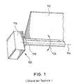
- FIG. 1 shows an example of the generic air flap drive devices, as they currently, for example, to regulate the fresh air or Recirculating air quantity can be used in automotive ventilation systems.
- the damper drive device comprises 100 an electric motor 116 with an internal (not shown) transmission, for pivoting an air damper 112 about a pivot axis 114 drives an output shaft 118.
- the electric motor 116 or the internal transmission associated therewith In terms of its strength, it is only able to force up to one certain size.
- the engine hub or the output shaft 118 directly to the fulcrum or the pivot axis 114 of the damper 112, wherein it is in this Air damper 112 is an off-center mounted "angle flap", that is the pivot point or the pivot axis 114 is not in the center of gravity the air damper 112.
- the invention is based on the object, the generic air damper drive devices to improve such that the above-explained Problems are eliminated or at least reduced.
- the air damper drive device is based on the generic State of the art in that a damping device for Damping is provided by applied to the damper torque.
- a damping device for Damping is provided by applied to the damper torque.
- inventively provided damping device are the on the air damper or the electric motor exerted large Torques so dampened that damage to the electric motor and or a possibly assigned thereto internal transmission avoided becomes.
- This solution is, but is not limited to, especially one direct connection of engine hub or output shaft and air damper advantageous. This applies even more if the air damper is stored off-center is, that is, if the pivot axis of the damper does not through their Focus extends.
- the damping device is a coupling element and a damping element, wherein the coupling element both is coupled to the output shaft as well as to the damping element.
- the Coupling element can be placed, for example, on the output shaft and / or attached to the air damper.
- a damping element can be any The damping element known to the person skilled in the art can be used, for example a linear damping element or a rotary damping element.
- the coupling element and the Damping element are coupled such that small movements of the output shaft be translated into larger movements by the damping element be steamed.
- the damping element a silicone oil damping element is.
- silicone oil rotational damping elements are used into consideration.
- the coupling element a includes toothed segment coupled to the output shaft.
- the damping element a includes gear in which engages the toothed segment.
- the invention makes it possible to damage one as a complete module supplied servomotor with internal gear to avoid by caused by vibrations and so on acting on the damper Torques are damped.
- FIG 2 is a generally designated 10 air damper drive device shown, which is intended to an air damper 12 about a pivot axis 14 to pivot.
- the damper drive device 10 includes an electric motor 16, to be associated with an unspecified internal gear can. About the electric motor 16, an output shaft 18 is driven, the on the pivot axis 14 of the damper 12 is located.
- the air damper 12 is itself to an eccentrically mounted angle flap, by their own weight in particular in case of shocks high torques 24 caused become.
- a damping device 20, 22 is provided in the illustrated case comprises a coupling element 20 and a damping element 22.
- the coupling element 20 has a toothed segment 26 and is on the air flap 12th attached.
- the damping element 22 is by a silicone oil rotational damping element realized that has a gear 28, in which the toothed segment 26 engages.
- the damping element 22nd via the coupling element 20 additionally driven by the electric motor 16, so that the large occurring torques 24 are damped. It takes over the sector gear 26, the translation of the small engine game in a larger Movement, which is then damped by the damping element 22.
Landscapes
- Physics & Mathematics (AREA)
- Thermal Sciences (AREA)
- Engineering & Computer Science (AREA)
- Mechanical Engineering (AREA)
- Air-Conditioning For Vehicles (AREA)
- Air-Flow Control Members (AREA)
- Cooling, Air Intake And Gas Exhaust, And Fuel Tank Arrangements In Propulsion Units (AREA)
- Fluid-Damping Devices (AREA)
- Superstructure Of Vehicle (AREA)
- Vehicle Body Suspensions (AREA)
Abstract
Description
- Figur 1
- eine eingangs bereits erläuterte schematische Darstellung einer Ausführungsform einer Luftklappenantriebsvorrichtung gemäß dem Stand der Technik; und
- Figur 2
- eine schematische Darstellung einer Ausführungsform der erfindungsgemäßen Luftklappenantriebsvorrichtung.
- 10; 100
- Luftklappenantriebsvorrichtung
- 12; 112
- Luftklappe
- 14; 114
- Schwenkachse
- 16; 116
- Elektromotor
- 18; 118
- Abtriebswelle
- 20
- Koppelelement
- 22
- Dämpfungselement
- 24; 124
- Drehmomente
- 26
- Zahnsegment
- 28
- Zahnrad
Claims (7)
- Luftklappenantriebsvorrichtung (10) zum Verschwenken einer Luftklappe (12; 112) eines Lüftungssystems, insbesondere eines Kraftfahrzeuglüftungssystems, um eine Schwenkachse(14; 114), mit einem Elektromotor (16; 116), der zum Verschwenken der Luftklappe(12; 112) eine Abtriebswelle (18;118) antreibt, dadurch gekennzeichnet, dass eine Dämpfungseinrichtung (20, 22) zur Dämpfung von auf die Luftklappe (10) ausgeübten Drehmomenten (24) vorgesehen ist.
- Luftklappenantriebsvorrichtung (10) nach Anspruch 1, dadurch gekennzeichnet, dass die Abtriebswelle (18) auf der Schwenkachse (14) liegt.
- Luftklappenantriebsvorrichtung (10) nach Anspruch 1 oder 2, dadurch gekennzeichnet, dass die Dämpfungseinrichtung (20, 22) ein Koppelelement (20) und ein Dämpfungselement (22) aufweist, wobei das Koppelelement (20) sowohl mit der Abtriebswelle (18) als auch mit dem Dämpfungselement (22) gekoppelt ist.
- Luftklappenantriebsvorrichtung (10) nach Anspruch 3, dadurch gekennzeichnet, dass das Koppelement (20) und das Dämpfungselement (22) derart gekoppelt sind, dass kleine Bewegungen der Abtriebswelle (18) in größere Bewegungen übersetzt werden, die von dem Dämpfungselement (22) gedämpft werden.
- Luftkiappenantriebsvorrichtung (10) nach Anspruch 3 oder 4, dadurch gekennzeichnet, dass das Dämpfungselement (22) ein Silikonöldämpfungselement ist.
- Luftklappenantriebsvorrichtung (10) nach einem der Ansprüche 3 bis 5, dadurch gekennzeichnet, dass das Koppelelement (20) ein mit der Abtriebswelle (18) gekoppeltes Zahnsegment (26) umfasst.
- Luftklappenantriebsvorrichtung (10) nach Anspruch 6, dadurch gekennzeichnet, dass das Dämpfungselement (22) ein Zahnrad (28) umfasst, in welches das Zahnsegment (26) eingreift.
Applications Claiming Priority (2)
| Application Number | Priority Date | Filing Date | Title |
|---|---|---|---|
| DE102004001369A DE102004001369A1 (de) | 2004-01-08 | 2004-01-08 | Luftklappenantriebsvorrichtung |
| DE102004001369 | 2004-01-08 |
Publications (3)
| Publication Number | Publication Date |
|---|---|
| EP1552972A2 true EP1552972A2 (de) | 2005-07-13 |
| EP1552972A3 EP1552972A3 (de) | 2005-11-16 |
| EP1552972B1 EP1552972B1 (de) | 2009-04-01 |
Family
ID=34585364
Family Applications (1)
| Application Number | Title | Priority Date | Filing Date |
|---|---|---|---|
| EP05000108A Expired - Lifetime EP1552972B1 (de) | 2004-01-08 | 2005-01-05 | Luftklappenantriebsvorrichtung |
Country Status (3)
| Country | Link |
|---|---|
| EP (1) | EP1552972B1 (de) |
| AT (1) | ATE427227T1 (de) |
| DE (2) | DE102004001369A1 (de) |
Family Cites Families (5)
| Publication number | Priority date | Publication date | Assignee | Title |
|---|---|---|---|---|
| JP3421484B2 (ja) * | 1995-09-01 | 2003-06-30 | 株式会社ニフコ | 回転ダンパー |
| DE29518173U1 (de) * | 1995-11-16 | 1996-01-11 | Itw-Ateco Gmbh, 22844 Norderstedt | Vorrichtung zur Dämpfung der Bewegung eines beweglich gelagerten Bauteils, insbesondere einer Klappe in einem Automobil o.dgl. |
| JPH09170637A (ja) * | 1995-12-18 | 1997-06-30 | Suzuki Sogyo Co Ltd | 開閉機構用ダンパ |
| DE29621043U1 (de) * | 1996-12-04 | 1997-01-23 | Itw-Ateco Gmbh, 22844 Norderstedt | Vorrichtung zur Dämpfung der Bewegung eines schwenkbar gelagerten Bauteils, insbesondere einer Klappe in einem Automobil |
| ES1048090Y (es) * | 2001-01-12 | 2001-11-01 | Vyr Valvuleria Y Riegos Por As | Cabezal basculante para aspersor maestro. |
-
2004
- 2004-01-08 DE DE102004001369A patent/DE102004001369A1/de not_active Ceased
-
2005
- 2005-01-05 DE DE502005006972T patent/DE502005006972D1/de not_active Expired - Lifetime
- 2005-01-05 AT AT05000108T patent/ATE427227T1/de not_active IP Right Cessation
- 2005-01-05 EP EP05000108A patent/EP1552972B1/de not_active Expired - Lifetime
Non-Patent Citations (1)
| Title |
|---|
| None |
Also Published As
| Publication number | Publication date |
|---|---|
| DE502005006972D1 (de) | 2009-05-14 |
| EP1552972A3 (de) | 2005-11-16 |
| ATE427227T1 (de) | 2009-04-15 |
| EP1552972B1 (de) | 2009-04-01 |
| DE102004001369A1 (de) | 2005-08-11 |
Similar Documents
| Publication | Publication Date | Title |
|---|---|---|
| EP3358218A2 (de) | Verstellvorrichtung zum verstellen eines fahrzeugsitzes entlang einer verschiebeachse | |
| DE102009015414A1 (de) | Elektrofahrzeug | |
| DE102019105998A1 (de) | Antriebseinrichtung für ein Kraftfahrzeug | |
| WO2016198323A1 (de) | Stellantrieb | |
| EP3246188A1 (de) | Nutzfahrzeug mit einem parallel-hybrid-antriebsstrang | |
| DE102013109997A1 (de) | Aktuator | |
| DE102011086020A1 (de) | Getriebeeinheit | |
| DE102019118220A1 (de) | Antriebseinrichtung für einen hybridischen Antriebsstrang | |
| DE102012105704A1 (de) | Massenträgheitserhöhungsvorrichtung für Schwungrad eines Verbrennungsmotors | |
| EP2398698B1 (de) | Bootsantrieb mit steuereinrichtung | |
| DE102019126440A1 (de) | Dämpfungsvorrichtung als Impact-Schutz; Getriebe; sowie Antriebseinheit | |
| EP1552972B1 (de) | Luftklappenantriebsvorrichtung | |
| DE202008017994U1 (de) | Schwerlastantriebsanordnung und damit angetriebene Mühle | |
| EP3892889A1 (de) | Spannungswellengetriebe | |
| DE102007048928A1 (de) | Spindelantrieb zum Antreiben eines bewegbaren Bauelements eines Kraftwagens | |
| DE102008039543A1 (de) | Rollenmühle | |
| DE102019121248A1 (de) | Kupplungsscheibe | |
| DE102011051529A1 (de) | Lenkgetriebe mit einer mechanischen begrenzung des abtriebswellenwinkels für schwere nutzkraftwagen mit elektrischer lenkunterstützung | |
| DE102004043136B3 (de) | Drehfeder, Drehfederersatz und Anordnung von Drehfedersätzen | |
| DE102017004333A1 (de) | Lenkanordnung für ein Fahrzeug mit einer Überlastschutzeinrichtung | |
| DE102020120683A1 (de) | Rotorwellenanordnung | |
| DE102020109755A1 (de) | Spannungswellengetriebe | |
| EP0984195A2 (de) | Geteiltes Schwungrad | |
| DE102019115322A1 (de) | Feedback-Aktuator für eine Lenkeinrichtung | |
| DE102007000937B4 (de) | Überlagerungslenkung |
Legal Events
| Date | Code | Title | Description |
|---|---|---|---|
| PUAI | Public reference made under article 153(3) epc to a published international application that has entered the european phase |
Free format text: ORIGINAL CODE: 0009012 |
|
| AK | Designated contracting states |
Kind code of ref document: A2 Designated state(s): AT BE BG CH CY CZ DE DK EE ES FI FR GB GR HU IE IS IT LI LT LU MC NL PL PT RO SE SI SK TR |
|
| AX | Request for extension of the european patent |
Extension state: AL BA HR LV MK YU |
|
| PUAL | Search report despatched |
Free format text: ORIGINAL CODE: 0009013 |
|
| AK | Designated contracting states |
Kind code of ref document: A3 Designated state(s): AT BE BG CH CY CZ DE DK EE ES FI FR GB GR HU IE IS IT LI LT LU MC NL PL PT RO SE SI SK TR |
|
| AX | Request for extension of the european patent |
Extension state: AL BA HR LV MK YU |
|
| RAP1 | Party data changed (applicant data changed or rights of an application transferred) |
Owner name: WEBASTO BUS GMBH |
|
| 17P | Request for examination filed |
Effective date: 20060217 |
|
| AKX | Designation fees paid |
Designated state(s): AT BE BG CH CY CZ DE DK EE ES FI FR GB GR HU IE IS IT LI LT LU MC NL PL PT RO SE SI SK TR |
|
| RAP1 | Party data changed (applicant data changed or rights of an application transferred) |
Owner name: SPHEROS GMBH |
|
| GRAP | Despatch of communication of intention to grant a patent |
Free format text: ORIGINAL CODE: EPIDOSNIGR1 |
|
| RAP1 | Party data changed (applicant data changed or rights of an application transferred) |
Owner name: SPHEROS GMBH |
|
| GRAS | Grant fee paid |
Free format text: ORIGINAL CODE: EPIDOSNIGR3 |
|
| GRAA | (expected) grant |
Free format text: ORIGINAL CODE: 0009210 |
|
| AK | Designated contracting states |
Kind code of ref document: B1 Designated state(s): AT BE BG CH CY CZ DE DK EE ES FI FR GB GR HU IE IS IT LI LT LU MC NL PL PT RO SE SI SK TR |
|
| REG | Reference to a national code |
Ref country code: GB Ref legal event code: FG4D Free format text: NOT ENGLISH |
|
| REG | Reference to a national code |
Ref country code: CH Ref legal event code: EP |
|
| REG | Reference to a national code |
Ref country code: IE Ref legal event code: FG4D Free format text: LANGUAGE OF EP DOCUMENT: GERMAN |
|
| REF | Corresponds to: |
Ref document number: 502005006972 Country of ref document: DE Date of ref document: 20090514 Kind code of ref document: P |
|
| PG25 | Lapsed in a contracting state [announced via postgrant information from national office to epo] |
Ref country code: SI Free format text: LAPSE BECAUSE OF FAILURE TO SUBMIT A TRANSLATION OF THE DESCRIPTION OR TO PAY THE FEE WITHIN THE PRESCRIBED TIME-LIMIT Effective date: 20090401 |
|
| NLV1 | Nl: lapsed or annulled due to failure to fulfill the requirements of art. 29p and 29m of the patents act | ||
| REG | Reference to a national code |
Ref country code: IE Ref legal event code: FD4D |
|
| PG25 | Lapsed in a contracting state [announced via postgrant information from national office to epo] |
Ref country code: ES Free format text: LAPSE BECAUSE OF FAILURE TO SUBMIT A TRANSLATION OF THE DESCRIPTION OR TO PAY THE FEE WITHIN THE PRESCRIBED TIME-LIMIT Effective date: 20090712 Ref country code: EE Free format text: LAPSE BECAUSE OF FAILURE TO SUBMIT A TRANSLATION OF THE DESCRIPTION OR TO PAY THE FEE WITHIN THE PRESCRIBED TIME-LIMIT Effective date: 20090401 Ref country code: FI Free format text: LAPSE BECAUSE OF FAILURE TO SUBMIT A TRANSLATION OF THE DESCRIPTION OR TO PAY THE FEE WITHIN THE PRESCRIBED TIME-LIMIT Effective date: 20090401 Ref country code: PT Free format text: LAPSE BECAUSE OF FAILURE TO SUBMIT A TRANSLATION OF THE DESCRIPTION OR TO PAY THE FEE WITHIN THE PRESCRIBED TIME-LIMIT Effective date: 20090902 Ref country code: LT Free format text: LAPSE BECAUSE OF FAILURE TO SUBMIT A TRANSLATION OF THE DESCRIPTION OR TO PAY THE FEE WITHIN THE PRESCRIBED TIME-LIMIT Effective date: 20090401 |
|
| PG25 | Lapsed in a contracting state [announced via postgrant information from national office to epo] |
Ref country code: NL Free format text: LAPSE BECAUSE OF FAILURE TO SUBMIT A TRANSLATION OF THE DESCRIPTION OR TO PAY THE FEE WITHIN THE PRESCRIBED TIME-LIMIT Effective date: 20090401 Ref country code: IS Free format text: LAPSE BECAUSE OF FAILURE TO SUBMIT A TRANSLATION OF THE DESCRIPTION OR TO PAY THE FEE WITHIN THE PRESCRIBED TIME-LIMIT Effective date: 20090801 Ref country code: SE Free format text: LAPSE BECAUSE OF FAILURE TO SUBMIT A TRANSLATION OF THE DESCRIPTION OR TO PAY THE FEE WITHIN THE PRESCRIBED TIME-LIMIT Effective date: 20090701 Ref country code: PL Free format text: LAPSE BECAUSE OF FAILURE TO SUBMIT A TRANSLATION OF THE DESCRIPTION OR TO PAY THE FEE WITHIN THE PRESCRIBED TIME-LIMIT Effective date: 20090401 |
|
| PG25 | Lapsed in a contracting state [announced via postgrant information from national office to epo] |
Ref country code: DK Free format text: LAPSE BECAUSE OF FAILURE TO SUBMIT A TRANSLATION OF THE DESCRIPTION OR TO PAY THE FEE WITHIN THE PRESCRIBED TIME-LIMIT Effective date: 20090401 Ref country code: CZ Free format text: LAPSE BECAUSE OF FAILURE TO SUBMIT A TRANSLATION OF THE DESCRIPTION OR TO PAY THE FEE WITHIN THE PRESCRIBED TIME-LIMIT Effective date: 20090401 Ref country code: RO Free format text: LAPSE BECAUSE OF FAILURE TO SUBMIT A TRANSLATION OF THE DESCRIPTION OR TO PAY THE FEE WITHIN THE PRESCRIBED TIME-LIMIT Effective date: 20090401 Ref country code: IE Free format text: LAPSE BECAUSE OF FAILURE TO SUBMIT A TRANSLATION OF THE DESCRIPTION OR TO PAY THE FEE WITHIN THE PRESCRIBED TIME-LIMIT Effective date: 20090401 |
|
| PLBE | No opposition filed within time limit |
Free format text: ORIGINAL CODE: 0009261 |
|
| STAA | Information on the status of an ep patent application or granted ep patent |
Free format text: STATUS: NO OPPOSITION FILED WITHIN TIME LIMIT |
|
| PG25 | Lapsed in a contracting state [announced via postgrant information from national office to epo] |
Ref country code: SK Free format text: LAPSE BECAUSE OF FAILURE TO SUBMIT A TRANSLATION OF THE DESCRIPTION OR TO PAY THE FEE WITHIN THE PRESCRIBED TIME-LIMIT Effective date: 20090401 |
|
| 26N | No opposition filed |
Effective date: 20100105 |
|
| PG25 | Lapsed in a contracting state [announced via postgrant information from national office to epo] |
Ref country code: BG Free format text: LAPSE BECAUSE OF FAILURE TO SUBMIT A TRANSLATION OF THE DESCRIPTION OR TO PAY THE FEE WITHIN THE PRESCRIBED TIME-LIMIT Effective date: 20090701 |
|
| BERE | Be: lapsed |
Owner name: SPHEROS G.M.B.H. Effective date: 20100131 |
|
| PG25 | Lapsed in a contracting state [announced via postgrant information from national office to epo] |
Ref country code: MC Free format text: LAPSE BECAUSE OF NON-PAYMENT OF DUE FEES Effective date: 20100131 |
|
| REG | Reference to a national code |
Ref country code: CH Ref legal event code: PL |
|
| GBPC | Gb: european patent ceased through non-payment of renewal fee |
Effective date: 20100105 |
|
| REG | Reference to a national code |
Ref country code: FR Ref legal event code: ST Effective date: 20100930 |
|
| PG25 | Lapsed in a contracting state [announced via postgrant information from national office to epo] |
Ref country code: GR Free format text: LAPSE BECAUSE OF FAILURE TO SUBMIT A TRANSLATION OF THE DESCRIPTION OR TO PAY THE FEE WITHIN THE PRESCRIBED TIME-LIMIT Effective date: 20090702 Ref country code: FR Free format text: LAPSE BECAUSE OF NON-PAYMENT OF DUE FEES Effective date: 20100201 Ref country code: LI Free format text: LAPSE BECAUSE OF NON-PAYMENT OF DUE FEES Effective date: 20100131 Ref country code: CH Free format text: LAPSE BECAUSE OF NON-PAYMENT OF DUE FEES Effective date: 20100131 |
|
| PG25 | Lapsed in a contracting state [announced via postgrant information from national office to epo] |
Ref country code: GB Free format text: LAPSE BECAUSE OF NON-PAYMENT OF DUE FEES Effective date: 20100105 |
|
| PG25 | Lapsed in a contracting state [announced via postgrant information from national office to epo] |
Ref country code: BE Free format text: LAPSE BECAUSE OF NON-PAYMENT OF DUE FEES Effective date: 20100131 |
|
| PG25 | Lapsed in a contracting state [announced via postgrant information from national office to epo] |
Ref country code: IT Free format text: LAPSE BECAUSE OF FAILURE TO SUBMIT A TRANSLATION OF THE DESCRIPTION OR TO PAY THE FEE WITHIN THE PRESCRIBED TIME-LIMIT Effective date: 20090401 |
|
| PG25 | Lapsed in a contracting state [announced via postgrant information from national office to epo] |
Ref country code: AT Free format text: LAPSE BECAUSE OF NON-PAYMENT OF DUE FEES Effective date: 20100105 |
|
| PG25 | Lapsed in a contracting state [announced via postgrant information from national office to epo] |
Ref country code: CY Free format text: LAPSE BECAUSE OF FAILURE TO SUBMIT A TRANSLATION OF THE DESCRIPTION OR TO PAY THE FEE WITHIN THE PRESCRIBED TIME-LIMIT Effective date: 20090401 |
|
| PG25 | Lapsed in a contracting state [announced via postgrant information from national office to epo] |
Ref country code: HU Free format text: LAPSE BECAUSE OF FAILURE TO SUBMIT A TRANSLATION OF THE DESCRIPTION OR TO PAY THE FEE WITHIN THE PRESCRIBED TIME-LIMIT Effective date: 20091002 Ref country code: LU Free format text: LAPSE BECAUSE OF NON-PAYMENT OF DUE FEES Effective date: 20100105 |
|
| PG25 | Lapsed in a contracting state [announced via postgrant information from national office to epo] |
Ref country code: TR Free format text: LAPSE BECAUSE OF FAILURE TO SUBMIT A TRANSLATION OF THE DESCRIPTION OR TO PAY THE FEE WITHIN THE PRESCRIBED TIME-LIMIT Effective date: 20090401 |
|
| PGFP | Annual fee paid to national office [announced via postgrant information from national office to epo] |
Ref country code: DE Payment date: 20220320 Year of fee payment: 18 |
|
| REG | Reference to a national code |
Ref country code: DE Ref legal event code: R119 Ref document number: 502005006972 Country of ref document: DE |
|
| PG25 | Lapsed in a contracting state [announced via postgrant information from national office to epo] |
Ref country code: DE Free format text: LAPSE BECAUSE OF NON-PAYMENT OF DUE FEES Effective date: 20230801 |