EP1552985B1 - Kraftfahrzeug Ausrüstungssystem - Google Patents
Kraftfahrzeug Ausrüstungssystem Download PDFInfo
- Publication number
- EP1552985B1 EP1552985B1 EP04030973A EP04030973A EP1552985B1 EP 1552985 B1 EP1552985 B1 EP 1552985B1 EP 04030973 A EP04030973 A EP 04030973A EP 04030973 A EP04030973 A EP 04030973A EP 1552985 B1 EP1552985 B1 EP 1552985B1
- Authority
- EP
- European Patent Office
- Prior art keywords
- vehicle equipment
- vehicle
- content
- equipment
- cpu
- Prior art date
- Legal status (The legal status is an assumption and is not a legal conclusion. Google has not performed a legal analysis and makes no representation as to the accuracy of the status listed.)
- Expired - Lifetime
Links
Images



Classifications
-
- B—PERFORMING OPERATIONS; TRANSPORTING
- B60—VEHICLES IN GENERAL
- B60K—ARRANGEMENT OR MOUNTING OF PROPULSION UNITS OR OF TRANSMISSIONS IN VEHICLES; ARRANGEMENT OR MOUNTING OF PLURAL DIVERSE PRIME-MOVERS IN VEHICLES; AUXILIARY DRIVES FOR VEHICLES; INSTRUMENTATION OR DASHBOARDS FOR VEHICLES; ARRANGEMENTS IN CONNECTION WITH COOLING, AIR INTAKE, GAS EXHAUST OR FUEL SUPPLY OF PROPULSION UNITS IN VEHICLES
- B60K35/00—Instruments specially adapted for vehicles; Arrangement of instruments in or on vehicles
- B60K35/10—Input arrangements, i.e. from user to vehicle, associated with vehicle functions or specially adapted therefor
-
- B—PERFORMING OPERATIONS; TRANSPORTING
- B60—VEHICLES IN GENERAL
- B60K—ARRANGEMENT OR MOUNTING OF PROPULSION UNITS OR OF TRANSMISSIONS IN VEHICLES; ARRANGEMENT OR MOUNTING OF PLURAL DIVERSE PRIME-MOVERS IN VEHICLES; AUXILIARY DRIVES FOR VEHICLES; INSTRUMENTATION OR DASHBOARDS FOR VEHICLES; ARRANGEMENTS IN CONNECTION WITH COOLING, AIR INTAKE, GAS EXHAUST OR FUEL SUPPLY OF PROPULSION UNITS IN VEHICLES
- B60K35/00—Instruments specially adapted for vehicles; Arrangement of instruments in or on vehicles
- B60K35/65—Instruments specially adapted for specific vehicle types or users, e.g. for left- or right-hand drive
- B60K35/654—Instruments specially adapted for specific vehicle types or users, e.g. for left- or right-hand drive the user being the driver
-
- B—PERFORMING OPERATIONS; TRANSPORTING
- B60—VEHICLES IN GENERAL
- B60K—ARRANGEMENT OR MOUNTING OF PROPULSION UNITS OR OF TRANSMISSIONS IN VEHICLES; ARRANGEMENT OR MOUNTING OF PLURAL DIVERSE PRIME-MOVERS IN VEHICLES; AUXILIARY DRIVES FOR VEHICLES; INSTRUMENTATION OR DASHBOARDS FOR VEHICLES; ARRANGEMENTS IN CONNECTION WITH COOLING, AIR INTAKE, GAS EXHAUST OR FUEL SUPPLY OF PROPULSION UNITS IN VEHICLES
- B60K35/00—Instruments specially adapted for vehicles; Arrangement of instruments in or on vehicles
- B60K35/65—Instruments specially adapted for specific vehicle types or users, e.g. for left- or right-hand drive
- B60K35/656—Instruments specially adapted for specific vehicle types or users, e.g. for left- or right-hand drive the user being a passenger
Definitions
- the present invention relates to an in-vehicle equipment system and is particularly suited, for example, to application to in-vehicle equipment system of connecting front-mounted in-vehicle equipment arranged in the vicinity of a driver's seat within a vehicle internal space and rear-mounted in-vehicle equipment arranged in the vicinity of rear seating.
- in-vehicle equipment such as car audio equipment, car televisions, car navigation systems and DVD (Digital Versatile Disc) players etc. are arranged within a vehicle internal space, with such in-vehicle equipment becoming more complex and multifunctional, year by year.
- DVD Digital Versatile Disc
- in-vehicle equipment 100 is typically arranged on the dashboard in the vicinity of the driver's seat.
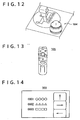
- the in-vehicle equipment 100 is then operated by a driver in the driver's seat or a passenger in a passenger seat through the operation of a remote controller 104 constituted by hardware switches 101 and 102 of the in-vehicle equipment 100, a rotary commander arranged in the vicinity of the shift lever shown in FIG. 12 , or through the use of a typical remote control 105 operated by a passenger in a rear seat as shown in FIG. 13 .
- in-vehicle computer systems also exist where input to a computer main unit located within the vehicle is possible via a keyboard brought to within the vehicle, for example, as disclosed in Japanese patent application publication number H10(1998)-260759 .
- the in-vehicle equipment 100 ( FIG. 11 ) of this configuration, the number of keys available for the hardware switches 101 and 102 and the remote controller 104 for a typical input means is small. Further, the screen size of a display screen 103 of the in-vehicle equipment 100 shown in FIG. 14 is also relatively small so that a scroll operation is required, which forces a driver in the driving seat to carry out a complex input operation.
- This object is achieved by an in-vehicle equipment system and an in-vehicle equipment control method according to the enclosed independent claims.
- Advantageous features of the present invention are defined in the corresponding subclaims.
- numeral 1 shows an overview of an in-vehicle equipment system according to a preferred embodiment of the present invention, having a configuration where front-mounted in-vehicle equipment 2 including, for example, an integrated audio unit having a CD (Compact Disc, a trademark) and MD (Mini Disc, a trademark) arranged at a substantially central portion of the dashboard in the vicinity of the driver's seat and rear-mounted in-vehicle equipment 3 constituted by a game device arranged in the vicinity of rear seating connected by a cable 4, for example.
- CD Compact Disc, a trademark
- MD Mini Disc, a trademark
- a display section 19 including an LCD (Liquid Crystal Display), and a hardware switch 18 are provided at the front-mounted in-vehicle equipment 2. CD's and MD's are then played back etc. via the hardware switch 18 and various types of display such as display of elapsed playback time are carried out at the display section 19.
- LCD Liquid Crystal Display
- a display device 5, keyboard 6, and game controller 7 are connected to the rear-mounted in-vehicle equipment 3. It is therefore possible for a passenger in a rear seat to enjoy games using the rear-mounted in-vehicle equipment 3 by operating the game controller 7, perform complex input operations, and input characters via the keyboard 6 while looking at the screen displayed at the display device 5.
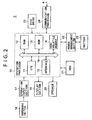
- the front-mounted in-vehicle equipment 2 operates based on electrical power supplied via a power management section 22 from a battery 23 or vehicle power supply (not shown).
- Prescribed processing is executed according to basic programs and application programs started up from ROM (Read Only Memory) 13 to RAM (Random Access Memory) 12 by a CPU (Central Processing Unit) 11 of an operation processor 10 via a bus 16. These processing results are then outputted at the display section 19 and the speaker 20 via an interface 15.
- the front-mounted in-vehicle equipment 2 receives instructions corresponding to rotating or pressing operations of the hardware switch 18 provided at the surface of the body using a CPU 11 of an operation processor 10 via an operation input section 17. Prescribed processing is then executed according to these instructions so that the disc drive 25 is operated so as to play back a CD or MD, audio files are read out from the non-volatile memory 14 and outputted from the speaker 20, or image data read-out from the hard disc 21 is outputted to the display section 19.
- front-mounted in-vehicle equipment 2 is not limited to instructions from the hardware switch 18 and it is also possible to execute prescribed processing according to instructions from the rear-mounted in-vehicle equipment 3 connected via a communication processor 24 and a cable 4.
- the rear-mounted in-vehicle equipment 3 shown in FIG. 3 also operates based on electrical power supplied from the battery 50 or on-vehicle power supply (not shown) via a power management section 49, executes prescribed processing according to basic programs and application programs started up from ROM 43 in RAM 42 via a bus 46 by a CPU 41 of an operation processor 40, and outputs the results of this processing from a display device 5 connected via an interface 45.
- the rear-mounted in-vehicle equipment 3 receives instructions inputted from the keyboard 6 or game controller 7 via an operation input section 47 using the CPU 41 of the operation processor 40.
- a disc drive 53 is then activated according to these instructions so that prescribed processing is executed in order that a DVD (Digital Versatile Disc) storing game software is played back and outputted as game images from speakers (not shown) of the display device 5, a saved game program is read from the non-volatile memory 44, or other various types of image data read-out from the hard disc drive 48 are outputted to the display device 5 and displayed, etc.
- DVD Digital Versatile Disc
- the rear-mounted in-vehicle equipment 3 also makes transfer requests relating to title information for music data at the front-mounted in-vehicle equipment 2 from the hard disc 21 of the front-mounted in-vehicle equipment 2 and the non-volatile memory 14 according to input operations with respect to the keyboard 6 and game controller 7 connected to the rear-mounted in-vehicle equipment 3.
- the rear-mounted in-vehicle equipment 3 has a sensor 52.
- the sensor 52 is used to detect whether or not a connection state is maintained with the front-mounted in-vehicle equipment 2, and to detect equipment information such as the presence of fire, heating temperature, operating time of the rear-mounted in-vehicle equipment 3, input information from the game controller 7 and stand-by time for the game controller 7, presence or absence of the batter 50 and the charge remaining, playback audio for a CD or MD, elapsed time for played-back images, remaining time, and media read errors. This information is then transmitted to the CPU 41 and is transmitted to the front-mounted in-vehicle equipment 2 from the CPU 41 via the communication processor 51 and the cable 4.
- the senor 52 is also capable of detecting whether or not a state of connection is maintained with external equipment such as a controller, PDA (Personal Digital Assistant), memory card, GPS (Global Positioning System) module, mouse, keyboard 6, headphones, power cable, camera, external hard disc, network cable, mobile telephone, LAN (Local Area Network) card, and external media.
- external equipment such as a controller, PDA (Personal Digital Assistant), memory card, GPS (Global Positioning System) module, mouse, keyboard 6, headphones, power cable, camera, external hard disc, network cable, mobile telephone, LAN (Local Area Network) card, and external media.
- step SP1 when title information for music data in the possession of the front-mounted in-vehicle equipment 2 is acquired by a passenger in the rear seating, when the CPU 41 of the rear-mounted in-vehicle equipment 3 recognizes the setting of edit mode for performing editing, a request to acquire music data title information is made to the front-mounted in-vehicle equipment 2 according to operation of the keyboard 6 and the game controller 7, and step SP2 is proceeded to.
- step SP11 the CPU 11 of the front-mounted in-vehicle equipment 2 recognizes the content of the acquisition request from the rear-mounted in-vehicle equipment 3, searches for, for example, music data title information in the possession of the front-mounted in-vehicle equipment 2 from the hard disc 21 according to this acquisition request, outputs the results of this search to the rear-mounted in-vehicle equipment 3 and proceeds to the following step SP12 so that processing for the front-mounted in-vehicle equipment 2 is complete.
- step SP2 the CPU 41 of the rear-mounted in-vehicle equipment 3 determines whether or not music data title information constituted by the search results have been acquired from the front-mounted in-vehicle equipment 2. When the results of this determination are negative, step SP3 is proceeded to, an error message such as "acquisition not possible" is displayed at the display device 5, and step SP1 is returned to.
- step SP2 When an affirmative result is obtained in step SP2, this is shown as the- CPU 41 of the rear-mounted in-vehicle equipment 3 displaying the acquisition of the music data title information.
- the CPU 41 of the rear-mounted in-vehicle equipment 3 then proceeds to the next step SP4 and the music data title information is displayed on the display device 5.
- the next step SP5 is then gone to, and the title information acquisition and display processing procedure are complete.
- the CPU 41 of the rear-mounted in-vehicle equipment 3 shown in FIG. 5 displays an editing screen 60 showing titles ("0001: ⁇ ", “0349: xxxx", "0674: ⁇ ⁇ ") for files (music data) divided up into folders in a directory structure.
- Various editing operations such as re-writing titles and directory names, changing the hierarchical structure of the directories or deleting files etc. may then be executed by a passenger using the keyboard 6.
- step SP21 the CPU 4 of the rear-mounted in-vehicle equipment 3 carries out editing operations using the editing screen 60 and then proceeds to step SP22 when it is confirmed that the overwrite button of the keyboard 6 has been pressed by a passenger in the rear seating.
- step SP22 the CPU 41 of the rear-mounted in-vehicle equipment 3 notifies the front-mounted in-vehicle equipment 2 that title editing processing by the rear-mounted in-vehicle equipment 3 according to pressing of the overwrite button is complete, transmits the content of these editing results and proceeds to the next step SP24.
- step SP31 the CPU 11 of the front-mounted in-vehicle equipment 2 determines whether or not there is no problem with overwriting the music data title information in the possession of the front-mounted in-vehicle equipment 2 with the content resulting from editing.
- step SP31 When an affirmative result is obtained in step SP31 in this respect, the CPU 11 of the front-mounted in-vehicle equipment 2 goes to the next step SP32, updates the data by overwriting with the content of the editing results, gives notification of overwrite completion to the rear-mounted in-vehicle equipment 3, proceeds to the next step SP33, and processing is complete.
- step SP24 at the CPU 41 of the rear-mounted in-vehicle equipment 3, a determination is made as to whether or not over-writing is complete.
- step SP25 is proceeded to, and the data re-writing processing procedure is complete.
- step SP24 the CPU 41 of the rear-mounted in-vehicle equipment 3 obtains a negative result when notification of overwrite completion is not received from the front-mounted in-vehicle equipment 2 and proceeds to step SP23, displays an indication that overwrite processing could not be carried out as error processing on the display device 5, and repeats the processing from step SP22 onwards.
- the rear-mounted in-vehicle equipment 3 acquires the music data title information in the possession of the front-mounted in-vehicle equipment 2. This is then displayed at the display device 5 of the rear-mounted in-vehicle equipment 3 so that a passenger in the rear seating can edit music title data etc. possessed by the front-mounted in-vehicle equipment 2 via the keyboard 6.
- the driver in the front seat does not have to edit their own music data titles and it is no longer necessary to perform complex input operations via the hardware switch 18.
- the results of editing titles of the music data at the rear-mounted in-vehicle equipment 3 are sent to the front-mounted in-vehicle equipment 2.
- the results of this editing are then confirmed by the driver and an invitation is also made to determine whether or not to perform overwrite processing.
- a driver support system can be implemented at the in-vehicle equipment system 1 where, intrinsically speaking, editing operations to be carried out by the driver at the front-mounted in-vehicle equipment 2 can be implemented by a passenger located in the vicinity of the rear seating instead of the driver via the rear-mounted in-vehicle equipment 3.
- the editing operation can be carried out via the keyboard 6 connected to the rear-mounted in-vehicle equipment 3 and the display device 5 with a screen size that is larger than that of the display section 19 of the front-mounted in-vehicle equipment 2 rather than via the hardware switch 18 of the front-mounted in-vehicle equipment 2.
- the input operation is therefore made more straightforward and easier for operation to the passenger with increased degree of freedom.
- the in-vehicle equipment system 1 it is possible for title information for music data possessed by the front-mounted in-vehicle equipment 2 to be acquired from the rear-mounted in-vehicle equipment 3 and for an editing operation to be carried out by a passenger on the display device 5 of the rear-mounted in-vehicle equipment 3 via the keyboard 6. It is therefore possible to implement a driver support system where an editing operation can be executed in a dramatically more straightforward manner inside a vehicle and where a driver is not forced to perform complex input operations.
- an in-vehicle equipment system 70 of a second preferred embodiment of the invention is configured from the front-mounted in-vehicle equipment 2 arranged at a substantially central portion of the dashboard in the vicinity of the front seating and the rear-mounted in-vehicle equipment 3 arranged in the vicinity of the rear seating connected by the cable 4, as with the in-vehicle equipment system 1 of the first embodiment.
- the display device 5 and the game controller 7 are connected, with a difference from the in-vehicle equipment system 1 of the first embodiment existing in that a game controller 71 is connected in place of the keyboard 6.
- Other aspects are the same as for the rear-mounted in-vehicle equipment 3 of the in-vehicle equipment system 1 of the first embodiment.
- the circuit configuration of the front-mounted in-vehicle equipment 2 and the rear-mounted in-vehicle equipment 3 is the same as for the in-vehicle equipment system 1 of the first embodiment and is not described, with a description being given only of the procedure for the control of processing of the front-mounted in-vehicle equipment 2 by the rear-mounted in-vehicle equipment 3.
- FIG. 8 to FIG. 10 of the flow for controlling the front-mounted in-vehicle equipment 2 from the rear-mounted in-vehicle equipment 3 at the in-vehicle equipment system 70.
- the CPU 41 of the rear-mounted in-vehicle equipment 3 makes a content title acquisition request to the front-mounted in-vehicle equipment 2 according to an operation of the game controller 71 and proceeds to the next step SP42.
- step SP61 the CPU 11 of the front-mounted in-vehicle equipment 2 recognizes the content of the content title acquisition request from the rear-mounted in-vehicle equipment 3, searches the hard disc 21for, for example, all content titles for movies etc. in the possession of the front-mounted in-vehicle equipment 2 as data according to this content title acquisition request, outputs the results of this search to the rear-mounted in-vehicle equipment 3 and proceeds to the following step SP62 so that processing for the front-mounted in-vehicle equipment 2 is complete.
- step SP42 the CPU 41 of the rear-mounted in-vehicle equipment 3 determines whether or not a plurality of content titles constituted by the search results have been acquired from the front-mounted in-vehicle equipment 2. When the results of this determination are negative, step SP43 is proceeded to, an error message such as "acquisition not possible" is displayed at the display device 5, and step SP41 is returned to.
- step SP42 the CPU 41 of the rear-mounted in-vehicle equipment 3 acquires all of the content titles from the front-mounted in-vehicle equipment 2.
- the CPU 41 of the rear-mounted in-vehicle equipment 3 then proceeds to the next step SP44, all of the content titles are displayed at the display device 5, the next step SP45 is gone to and the acquisition of the content titles and the display processing procedure are complete.
- the CPU 41 of the rear-mounted in-vehicle equipment 3 displays a content switching screen 80 showing a list of all the content titles possessed by the front-mounted in-vehicle equipment 2 at the display device 5, and, for example, displays a content title 81 for the number 0003 selected by a passenger in the rear seating in reverse. This may then be dragged and dropped by a passenger so that, for example, the content playback order of numbers 0001, 0002, 0015, Vietnamese, 0003 and 0016 is changed over in response to shifting of the portion for the content title for number 0015.
- the CPU 41 of the rear-mounted in-vehicle equipment 3 not only changes the content playback order but is also capable of changing the numbers 0001, 0002, ., 0015, and 0016 by deleting the content title 81 of the number 0003 displayed in an inverted manner.
- the in-vehicle equipment system 70 it is possible to set a data protection function in advance with respect to both the rear-mounted in-vehicle equipment 3 and the front-mounted in-vehicle equipment 2 in order to prevent content from being erroneously deleted by a passenger in the rear seating without the knowledge of a driver in the front seating.
- step SP71 after carrying out editing at the content switching screen 80 in step SP71, when the CPU 41 of the rear-mounted in-vehicle equipment 3 confirms pressing of the overwrite button by a passenger in the rear seating, the next step SP72 is proceeded to.
- step SP72 the CPU 41 of the rear-mounted in-vehicle equipment 3 notifies the front-mounted in-vehicle equipment 2 that content switching processing by the rear-mounted in-vehicle equipment 3 is complete, transmits the content of these content switching results and proceeds to the next step SP74.
- step SP81 the CPU 11 of the front-mounted in-vehicle equipment 2 determines whether or not there is no problem with overwriting the content title in the possession of the front-mounted in-vehicle equipment 2 with the content switching results.
- step SP81 the CPU 11 of the front-mounted in-vehicle equipment 2 goes to the next step SP82, updates the data for the content title by overwriting with the content switching results, transmits notification of overwrite completion to the rear-mounted in-vehicle equipment 3, proceeds to the next step SP83, and processing is complete.
- step SP74 the CPU 41 of the rear-mounted in-vehicle equipment 3 determines whether or not overwriting is complete, obtains a negative result when notification of overwrite completion is not received from the front-mounted in-vehicle equipment 2 and proceeds to step SP73, displays an indication that overwrite processing could not be carried out as error processing on the display device 5, and repeats the processing from step SP72 onwards.
- step SP74 when receipt of an overwrite completion notification from the front-mounted in-vehicle equipment 2 is detected by the CPU 41 of the rear-mounted in-vehicle equipment 3, an affirmative result is obtained, the next step SP75 is proceeded to, and the content switching processing procedure is complete.
- the driver in the front seat does not have to carry out content switching operations by themselves and it is no longer necessary to perform complex input operations via the hardware switch 18.
- the content switching results are sent to the front-mounted in-vehicle equipment 2.
- the content switching results are then confirmed by the driver and an invitation is also made to determine whether or not to perform overwrite processing. This means that it is possible to reflect the intent of the driver in the front seat in the content of the results of content switching carried out by a passenger in the rear seating. It is therefore possible to prevent important content titles from being overwritten by the driver and to prevent the playback order of the content from being changed around, etc.
- a driver support system can be implemented at the in-vehicle equipment system 70 where, intrinsically speaking, content switching operations to be carried out by the driver at the front-mounted in-vehicle equipment 2 can be implemented by a passenger located in the vicinity of the rear seating instead of the driver via the rear-mounted in-vehicle equipment 3.
- the content switching operation can be carried out via the keyboard 6 connected to the rear-mounted in-vehicle equipment 3 and the display device 5 with a screen size that is larger than that of the display section 19 of the front-mounted in-vehicle equipment 2 rather than via the hardware switch 18 of the front-mounted in-vehicle equipment 2.
- the input operation is therefore markedly more straightforward and easier for operation and increases the degree of freedom of the passenger.
- the in-vehicle equipment system 70 it is possible for all of the content titles for content possessed by the front-mounted in-vehicle equipment 2 to be acquired from the rear-mounted in-vehicle equipment 3 and for a content switching operation to be carried out by a passenger on the display device 5 of the rear-mounted in-vehicle equipment 3 via the game controller 71. It is therefore possible to implement a driver support system where the content switching operation can be executed in a dramatically more straightforward manner inside a vehicle and where a driver is not forced to perform complex input operations.
- the present invention is by no means limited in this respect and may also be applied to switching sources such as CDs and MDs the front-mounted in-vehicle equipment 2 is capable of playing back on a screen of the display device 5 of the rear-mounted in-vehicle equipment 3.
- the present invention is by no means limited in this respect, and may also be applied to executing various setting operations that are required to be carried out for a navigation function such as navigation destination setting or route search etc. on a screen of a display device 5 of the rear-mounted in-vehicle equipment 3 and sending these results to the front-mounted in-vehicle equipment 2 so that these results are reflected.
- a navigation function such as navigation destination setting or route search etc.
- connection having a cable 4 is taken to be the means for connecting the front-mounted in-vehicle equipment 2 and the rear-mounted in-vehicle equipment 3 but the present invention is by no means limited in this respect, so that connection can be carried out by connecting means other than cables or wires and also by wireless or contactless connection employing IEEE (Institute of Electrical and Electronic Engineers) 802.11g or others, or Bluetooth communication system, for example, may also be employed.
- IEEE Institute of Electrical and Electronic Engineers
- Bluetooth communication system for example
- the in-vehicle equipment systems 1 and 70 are configured from front-mounted in-vehicle equipment 2 comprised of an integrated audio unit of a CD and an MD and a rear-mounted in-vehicle equipment 3 constituted by a game device.
- the present invention is by no means limited in this respect and the in-vehicle equipment systems 1 and 70 may also be configured from front-mounted in-vehicle equipment 2 constituted by a navigation device and rear-mounted in-vehicle equipment 3 constituted by a DVD player, or by in-vehicle equipment systems 1 and 70 configured from other types of front-mounted in-vehicle equipment 2 and rear-mounted in-vehicle equipment 3.
- results of editing relating to music data titles and content titles and content switching results for switching content playback order carried out at the rear-mounted in-vehicle equipment 3 are sent to the front-mounted in-vehicle equipment 2 so that a driver in the front seating is invited to make a determination as to whether or not to overwrite using the editing results or the content switching results.
- the present invention is by no means limited in this respect and it is also possible to send the content sequentially to the front-mounted in-vehicle equipment 2 in intermediate stages of editing relating to the title or in intermediate stages for switching the content playback order so as to invite a determination by the driver in the front seating.
- the in-vehicle equipment system may be utilized in various applications for controlling front-mounted in-vehicle equipment from rear-mounted in-vehicle equipment at positions separated from each other with, for example, front-mounted in-vehicle equipment positioned at the front of the vehicle internal space and rear-mounted in-vehicle equipment positioned at the rear of the vehicle internal space.
Landscapes
- Engineering & Computer Science (AREA)
- Chemical & Material Sciences (AREA)
- Combustion & Propulsion (AREA)
- Transportation (AREA)
- Mechanical Engineering (AREA)
- Fittings On The Vehicle Exterior For Carrying Loads, And Devices For Holding Or Mounting Articles (AREA)
Claims (6)
- Ausrüstungssystem im Inneren eines Fahrzeugs, umfassend:eine vorderseitig montierte Ausrüstung (2) im Inneren eines Fahrzeugs, welche an einem vorderen Abschnitt eines Fahrzeuginnenraums angeordnet ist;eine hinten montierte Ausrüstung (3) im Inneren eines Fahrzeugs, welche an einem hinteren Abschnitt des Fahrzeuginnenraums angeordnet ist; undeine Verbindung (24, 4, 51), welche angepasst ist, um die vorderseitig montierte Ausrüstung (2) im Inneren eines Fahrzeugs und die hinten montierte Ausrüstung (3) im Inneren eines Fahrzeugs zu verbinden; wobeidie hinten montierte Ausrüstung (3) im Inneren eines Fahrzeugs angepasst ist, um die vorderseitig montierte Ausrüstung (2) im Inneren eines Fahrzeugs über eine Eingabeeinrichtung (6, 47) zu steuern,
dadurch gekennzeichnet, dass
die hinten montierte Ausrüstung (3) im Inneren eines Fahrzeugs angepasst ist, um ein Einstellen und eine Freigabe einer Datenschutzfunktion der vorderseitig montierten Ausrüstung im Inneren eines Fahrzeugs zu steuern. - Ausrüstungssystem im Inneren eines Fahrzeugs wie in Anspruch 1 beschrieben, wobei
die hinten montierte Ausrüstung (3) im Inneren eines Fahrzeugs angepasst ist, um eine Inhaltsquelle, welche von der vorderseitig montierten Ausrüstung (2) im Inneren eines Fahrzeugs ausgegeben wird, zu schalten. - Ausrüstungssystem im Inneren eines Fahrzeugs wie in Anspruch 1 oder 2 beschrieben, wobei
die hinten montierte Ausrüstung (3) im Inneren eines Fahrzeugs angepasst ist, um ein Bild, welches durch die vorderseitig montierte Ausrüstung (2) im Inneren eines Fahrzeugs angezeigt wird, zu schalten. - Ausrüstungssystem im Inneren eines Fahrzeugs wie in irgendeinem der Ansprüche 1 bis 3 beschrieben, wobei
eine Betätigung des Editierinhalts, welcher der vorderseitig montierten Ausrüstung (2) im Inneren eines Fahrzeugs gehört, unter Verwendung eines Bildschirms (5) der hinten montierten Ausrüstung (3) im Inneren eines Fahrzeugs ausgeführt wird. - Ausrüstungssystem im Inneren eines Fahrzeugs wie in irgendeinem der Ansprüche 1 bis 3 beschrieben, wobei
eine Betätigung des Editierinhalts einer Speichervorrichtung, welche der vorderseitig montierten Ausrüstung (2) im Inneren eines Fahrzeugs gehört, unter Verwendung eines Bildschirms (5) der hinten montierten Ausrüstung (3) im Inneren eines Fahrzeugs ausgeführt wird. - Steuerungsverfahren für Ausrüstung im Inneren eines Fahrzeugs, welches in dem Ausrüstungssystem im Inneren eines Fahrzeugs gemäß irgendeinem der Ansprüche 1 bis 5 durchgeführt wird, welches die folgenden Schritte umfasst:Verbinden (24, 4, 51) der vorderseitig montierten Ausrüstung (2) im Inneren eines Fahrzeugs und der hinten montierten Ausrüstung (3) im Inneren eines Fahrzeugs; undSteuern der vorderseitig montierten Ausrüstung (2) im Inneren eines Fahrzeugs von der hinten montierten Ausrüstung (3) im Inneren eines Fahrzeugs über eine Eingabeeinrichtung (6, 47),dadurch gekennzeichnet, dass
die hinten montierte Ausrüstung (3) im Inneren eines Fahrzeugs ein Einstellen und eine Freigabe einer Datenschutzfunktion der vorderseitig montierten Ausrüstung im Inneren eines Fahrzeugs steuert.
Applications Claiming Priority (2)
| Application Number | Priority Date | Filing Date | Title |
|---|---|---|---|
| JP2004004790A JP4129685B2 (ja) | 2004-01-09 | 2004-01-09 | 車載機器システム及び車載機器の制御方法 |
| JP2004004790 | 2004-01-09 |
Publications (2)
| Publication Number | Publication Date |
|---|---|
| EP1552985A1 EP1552985A1 (de) | 2005-07-13 |
| EP1552985B1 true EP1552985B1 (de) | 2008-03-12 |
Family
ID=34587739
Family Applications (1)
| Application Number | Title | Priority Date | Filing Date |
|---|---|---|---|
| EP04030973A Expired - Lifetime EP1552985B1 (de) | 2004-01-09 | 2004-12-29 | Kraftfahrzeug Ausrüstungssystem |
Country Status (5)
| Country | Link |
|---|---|
| US (3) | US7496438B2 (de) |
| EP (1) | EP1552985B1 (de) |
| JP (1) | JP4129685B2 (de) |
| DE (1) | DE602004012375T2 (de) |
| ES (1) | ES2301928T3 (de) |
Families Citing this family (16)
| Publication number | Priority date | Publication date | Assignee | Title |
|---|---|---|---|---|
| JP4129685B2 (ja) * | 2004-01-09 | 2008-08-06 | ソニー株式会社 | 車載機器システム及び車載機器の制御方法 |
| KR100728505B1 (ko) * | 2006-06-21 | 2007-06-14 | 주식회사 대우일렉트로닉스 | 착탈식 자동차용 멀티미디어 재생 장치 프론트 패널을이용한 게임 장치 |
| US8016352B2 (en) * | 2006-10-31 | 2011-09-13 | Edward Liu | Vehicle multimedia system for vehicle |
| DE102007004923A1 (de) * | 2007-02-01 | 2008-08-21 | Volkswagen Ag | Anzeige- und Bedienvorrichtung eines Kraftfahrzeugs zum Erfassen von nutzerabhängigen Parametern |
| US8094831B2 (en) * | 2007-10-25 | 2012-01-10 | Honda Motor Co., Ltd. | Supplemental audio output box |
| JP2009137392A (ja) * | 2007-12-05 | 2009-06-25 | Mitsubishi Electric Corp | 表示制御装置 |
| DE102008031718A1 (de) * | 2008-07-04 | 2010-01-07 | Bayerische Motoren Werke Aktiengesellschaft | Kraftfahrzeug |
| JP5406599B2 (ja) | 2009-06-08 | 2014-02-05 | クラリオン株式会社 | 車載器の入力装置 |
| JP5722532B2 (ja) | 2009-06-12 | 2015-05-20 | クラリオン株式会社 | 車載器の入力装置 |
| JPWO2010146840A1 (ja) * | 2009-06-15 | 2012-11-29 | 株式会社アルバック | 基板搬送装置 |
| CN102267385A (zh) * | 2010-06-03 | 2011-12-07 | 上海荣乐汽车电子有限公司 | 集成式数字化汽车仪表 |
| BR112013033928B1 (pt) | 2011-07-08 | 2021-09-14 | Nissan Motor Co., Ltd | Dispositivo de exibição de informações para veículo |
| CN102490667B (zh) * | 2011-10-11 | 2015-07-29 | 科世达(上海)管理有限公司 | 一种汽车中控系统 |
| US9193312B2 (en) * | 2014-02-20 | 2015-11-24 | Ford Global Technologies, Llc | Occupant communication system and control method |
| US20170094346A1 (en) * | 2014-05-22 | 2017-03-30 | GM Global Technology Operations LLC | Systems and methods for utilizing smart toys with vehicle entertainment systems |
| DE102021117914A1 (de) * | 2021-07-12 | 2023-01-12 | Audi Aktiengesellschaft | Unterhaltungssystem |
Family Cites Families (14)
| Publication number | Priority date | Publication date | Assignee | Title |
|---|---|---|---|---|
| US5823599A (en) * | 1995-09-06 | 1998-10-20 | Textron Automotive Company Inc. | Mechanized floor console |
| US5794164A (en) | 1995-11-29 | 1998-08-11 | Microsoft Corporation | Vehicle computer system |
| JPH10260759A (ja) | 1997-03-19 | 1998-09-29 | Furukawa Electric Co Ltd:The | 車載用コンピュータシステム |
| US6446080B1 (en) * | 1998-05-08 | 2002-09-03 | Sony Corporation | Method for creating, modifying, and playing a custom playlist, saved as a virtual CD, to be played by a digital audio/visual actuator device |
| JP3889510B2 (ja) * | 1998-05-21 | 2007-03-07 | アルパイン株式会社 | 車載機器制御システム |
| JP3321590B2 (ja) | 1998-07-02 | 2002-09-03 | 萬太郎 西川 | 駐車車輛と運転者との間の通信装置 |
| US6356971B1 (en) * | 1999-03-04 | 2002-03-12 | Sony Corporation | System for managing multimedia discs, tracks and files on a standalone computer |
| JP3926529B2 (ja) | 2000-03-01 | 2007-06-06 | アルパイン株式会社 | オーディオシステム |
| WO2001083253A1 (en) | 2000-04-27 | 2001-11-08 | Mitsubishi Denki Kabushiki Kaisha | Display device |
| JP2001310683A (ja) | 2000-04-28 | 2001-11-06 | Tokai Rika Co Ltd | 車両用遠隔操作装置 |
| US7200357B2 (en) | 2000-10-20 | 2007-04-03 | Universal Electronics Inc. | Automotive storage and playback device and method for using the same |
| JP4270881B2 (ja) * | 2001-05-28 | 2009-06-03 | 三菱電機株式会社 | 移動体用機器配設装置 |
| JP2003089330A (ja) | 2001-09-18 | 2003-03-25 | Matsushita Electric Ind Co Ltd | 車載用音響映像制御装置 |
| JP4129685B2 (ja) * | 2004-01-09 | 2008-08-06 | ソニー株式会社 | 車載機器システム及び車載機器の制御方法 |
-
2004
- 2004-01-09 JP JP2004004790A patent/JP4129685B2/ja not_active Expired - Fee Related
- 2004-12-21 US US11/016,811 patent/US7496438B2/en not_active Expired - Fee Related
- 2004-12-29 ES ES04030973T patent/ES2301928T3/es not_active Expired - Lifetime
- 2004-12-29 EP EP04030973A patent/EP1552985B1/de not_active Expired - Lifetime
- 2004-12-29 DE DE602004012375T patent/DE602004012375T2/de not_active Expired - Lifetime
-
2009
- 2009-01-07 US US12/349,969 patent/US7774114B2/en not_active Expired - Fee Related
-
2010
- 2010-07-02 US US12/830,006 patent/US20100268400A1/en not_active Abandoned
Also Published As
| Publication number | Publication date |
|---|---|
| ES2301928T3 (es) | 2008-07-01 |
| DE602004012375D1 (de) | 2008-04-24 |
| US20100268400A1 (en) | 2010-10-21 |
| US7496438B2 (en) | 2009-02-24 |
| DE602004012375T2 (de) | 2009-03-26 |
| JP4129685B2 (ja) | 2008-08-06 |
| US7774114B2 (en) | 2010-08-10 |
| JP2005193875A (ja) | 2005-07-21 |
| EP1552985A1 (de) | 2005-07-13 |
| US20060041351A1 (en) | 2006-02-23 |
| US20090125185A1 (en) | 2009-05-14 |
Similar Documents
| Publication | Publication Date | Title |
|---|---|---|
| US7774114B2 (en) | In-vehicle equipment system | |
| US7222207B2 (en) | Portable computing device-integrated appliance | |
| US6990208B1 (en) | Vehicle sound system | |
| US7505839B2 (en) | Vehicular data recording device | |
| US6876922B2 (en) | Navigation system | |
| WO2001067758A1 (en) | Audio/visual server | |
| US6600993B1 (en) | Navigation system | |
| JP2007042253A (ja) | コンテンツ取得装置、コンテンツ取得方法及びコンテンツ取得プログラム | |
| US8588994B2 (en) | On-vehicle device | |
| JP5641906B2 (ja) | 操作方法及び音響装置 | |
| JP2008195394A (ja) | 車載機器システム | |
| JP4347255B2 (ja) | 端末装置、コンテンツの消去/転送制御システム及びコンテンツ消去制御方法 | |
| JP2004106797A (ja) | 車載システム、車両用ディスプレイ装置、ショートカット用オブジェクトの登録方法、及び、外部機器 | |
| JP3607195B2 (ja) | ナビゲーション装置 | |
| JP3584650B2 (ja) | ナビゲーション装置 | |
| AU744507B2 (en) | Device for inputting title of recording medium | |
| JPH0962183A (ja) | 車載用ナビゲーション装置 | |
| JPH06201390A (ja) | ナビゲーション装置 | |
| JP2000313289A (ja) | 車両用スイッチ制御装置 | |
| JP2009266265A (ja) | 階層構造を持つ音楽ファイルの再生機能を有する車載装置 | |
| JPS63187488A (ja) | 記録担体再生装置 | |
| JP2007269173A (ja) | 車載用情報機器、車載用情報機器の制御方法および制御プログラム | |
| JP2006324005A (ja) | 再生装置及び再生プログラム | |
| JP2007004975A (ja) | 再生装置、再生システム、及び再生プログラム | |
| JP2004171319A (ja) | 文字情報の転送/表示システム |
Legal Events
| Date | Code | Title | Description |
|---|---|---|---|
| PUAI | Public reference made under article 153(3) epc to a published international application that has entered the european phase |
Free format text: ORIGINAL CODE: 0009012 |
|
| AK | Designated contracting states |
Kind code of ref document: A1 Designated state(s): AT BE BG CH CY CZ DE DK EE ES FI FR GB GR HU IE IS IT LI LT LU MC NL PL PT RO SE SI SK TR |
|
| AX | Request for extension of the european patent |
Extension state: AL BA HR LV MK YU |
|
| 17P | Request for examination filed |
Effective date: 20060113 |
|
| AKX | Designation fees paid |
Designated state(s): DE ES FR GB IT NL |
|
| GRAP | Despatch of communication of intention to grant a patent |
Free format text: ORIGINAL CODE: EPIDOSNIGR1 |
|
| GRAS | Grant fee paid |
Free format text: ORIGINAL CODE: EPIDOSNIGR3 |
|
| GRAA | (expected) grant |
Free format text: ORIGINAL CODE: 0009210 |
|
| AK | Designated contracting states |
Kind code of ref document: B1 Designated state(s): DE ES FR GB IT NL |
|
| REG | Reference to a national code |
Ref country code: GB Ref legal event code: FG4D |
|
| REF | Corresponds to: |
Ref document number: 602004012375 Country of ref document: DE Date of ref document: 20080424 Kind code of ref document: P |
|
| REG | Reference to a national code |
Ref country code: ES Ref legal event code: FG2A Ref document number: 2301928 Country of ref document: ES Kind code of ref document: T3 |
|
| ET | Fr: translation filed | ||
| PLBE | No opposition filed within time limit |
Free format text: ORIGINAL CODE: 0009261 |
|
| STAA | Information on the status of an ep patent application or granted ep patent |
Free format text: STATUS: NO OPPOSITION FILED WITHIN TIME LIMIT |
|
| 26N | No opposition filed |
Effective date: 20081215 |
|
| PGFP | Annual fee paid to national office [announced via postgrant information from national office to epo] |
Ref country code: ES Payment date: 20141218 Year of fee payment: 11 |
|
| REG | Reference to a national code |
Ref country code: DE Ref legal event code: R084 Ref document number: 602004012375 Country of ref document: DE |
|
| REG | Reference to a national code |
Ref country code: DE Ref legal event code: R084 Ref document number: 602004012375 Country of ref document: DE Effective date: 20150410 |
|
| REG | Reference to a national code |
Ref country code: FR Ref legal event code: PLFP Year of fee payment: 12 |
|
| REG | Reference to a national code |
Ref country code: FR Ref legal event code: PLFP Year of fee payment: 13 |
|
| REG | Reference to a national code |
Ref country code: ES Ref legal event code: FD2A Effective date: 20170126 |
|
| PG25 | Lapsed in a contracting state [announced via postgrant information from national office to epo] |
Ref country code: ES Free format text: LAPSE BECAUSE OF NON-PAYMENT OF DUE FEES Effective date: 20151230 |
|
| REG | Reference to a national code |
Ref country code: FR Ref legal event code: PLFP Year of fee payment: 14 |
|
| PGFP | Annual fee paid to national office [announced via postgrant information from national office to epo] |
Ref country code: NL Payment date: 20191219 Year of fee payment: 16 |
|
| PGFP | Annual fee paid to national office [announced via postgrant information from national office to epo] |
Ref country code: IT Payment date: 20191230 Year of fee payment: 16 Ref country code: FR Payment date: 20191219 Year of fee payment: 16 |
|
| PGFP | Annual fee paid to national office [announced via postgrant information from national office to epo] |
Ref country code: GB Payment date: 20191220 Year of fee payment: 16 |
|
| PGFP | Annual fee paid to national office [announced via postgrant information from national office to epo] |
Ref country code: DE Payment date: 20201211 Year of fee payment: 17 |
|
| REG | Reference to a national code |
Ref country code: NL Ref legal event code: MM Effective date: 20210101 |
|
| GBPC | Gb: european patent ceased through non-payment of renewal fee |
Effective date: 20201229 |
|
| PG25 | Lapsed in a contracting state [announced via postgrant information from national office to epo] |
Ref country code: NL Free format text: LAPSE BECAUSE OF NON-PAYMENT OF DUE FEES Effective date: 20210101 |
|
| PG25 | Lapsed in a contracting state [announced via postgrant information from national office to epo] |
Ref country code: FR Free format text: LAPSE BECAUSE OF NON-PAYMENT OF DUE FEES Effective date: 20201231 Ref country code: IT Free format text: LAPSE BECAUSE OF NON-PAYMENT OF DUE FEES Effective date: 20201229 |
|
| PG25 | Lapsed in a contracting state [announced via postgrant information from national office to epo] |
Ref country code: GB Free format text: LAPSE BECAUSE OF NON-PAYMENT OF DUE FEES Effective date: 20201229 |
|
| REG | Reference to a national code |
Ref country code: DE Ref legal event code: R119 Ref document number: 602004012375 Country of ref document: DE |
|
| PG25 | Lapsed in a contracting state [announced via postgrant information from national office to epo] |
Ref country code: DE Free format text: LAPSE BECAUSE OF NON-PAYMENT OF DUE FEES Effective date: 20220701 |