EP1553032A1 - Méthode de remplacement améliorée et dispositif à rouleaux d'alimentation de papier - Google Patents
Méthode de remplacement améliorée et dispositif à rouleaux d'alimentation de papier Download PDFInfo
- Publication number
- EP1553032A1 EP1553032A1 EP05000163A EP05000163A EP1553032A1 EP 1553032 A1 EP1553032 A1 EP 1553032A1 EP 05000163 A EP05000163 A EP 05000163A EP 05000163 A EP05000163 A EP 05000163A EP 1553032 A1 EP1553032 A1 EP 1553032A1
- Authority
- EP
- European Patent Office
- Prior art keywords
- pick
- frame
- roller
- bearing
- assembly
- Prior art date
- Legal status (The legal status is an assumption and is not a legal conclusion. Google has not performed a legal analysis and makes no representation as to the accuracy of the status listed.)
- Granted
Links
Images


Classifications
-
- B—PERFORMING OPERATIONS; TRANSPORTING
- B65—CONVEYING; PACKING; STORING; HANDLING THIN OR FILAMENTARY MATERIAL
- B65H—HANDLING THIN OR FILAMENTARY MATERIAL, e.g. SHEETS, WEBS, CABLES
- B65H3/00—Separating articles from piles
- B65H3/46—Supplementary devices or measures to assist separation or prevent double feed
- B65H3/52—Friction retainers acting on under or rear side of article being separated
- B65H3/5246—Driven retainers, i.e. the motion thereof being provided by a dedicated drive
- B65H3/5253—Driven retainers, i.e. the motion thereof being provided by a dedicated drive the retainers positioned under articles separated from the top of the pile
- B65H3/5261—Retainers of the roller type, e.g. rollers
-
- B—PERFORMING OPERATIONS; TRANSPORTING
- B65—CONVEYING; PACKING; STORING; HANDLING THIN OR FILAMENTARY MATERIAL
- B65H—HANDLING THIN OR FILAMENTARY MATERIAL, e.g. SHEETS, WEBS, CABLES
- B65H3/00—Separating articles from piles
- B65H3/02—Separating articles from piles using friction forces between articles and separator
- B65H3/06—Rollers or like rotary separators
-
- B—PERFORMING OPERATIONS; TRANSPORTING
- B65—CONVEYING; PACKING; STORING; HANDLING THIN OR FILAMENTARY MATERIAL
- B65H—HANDLING THIN OR FILAMENTARY MATERIAL, e.g. SHEETS, WEBS, CABLES
- B65H2402/00—Constructional details of the handling apparatus
- B65H2402/50—Machine elements
- B65H2402/52—Bearings, e.g. magnetic or hydrostatic bearings
-
- B—PERFORMING OPERATIONS; TRANSPORTING
- B65—CONVEYING; PACKING; STORING; HANDLING THIN OR FILAMENTARY MATERIAL
- B65H—HANDLING THIN OR FILAMENTARY MATERIAL, e.g. SHEETS, WEBS, CABLES
- B65H2405/00—Parts for holding the handled material
- B65H2405/30—Other features of supports for sheets
- B65H2405/31—Supports for sheets fully removable from the handling machine, e.g. cassette
-
- B—PERFORMING OPERATIONS; TRANSPORTING
- B65—CONVEYING; PACKING; STORING; HANDLING THIN OR FILAMENTARY MATERIAL
- B65H—HANDLING THIN OR FILAMENTARY MATERIAL, e.g. SHEETS, WEBS, CABLES
- B65H2601/00—Problem to be solved or advantage achieved
- B65H2601/30—Facilitating or easing
- B65H2601/32—Facilitating or easing entities relating to handling machine
- B65H2601/324—Removability or inter-changeability of machine parts, e.g. for maintenance
Definitions
- the present application relates to a removable pick module for use in a sheet feeding office machine such as a printer, photocopier or high capacity paper feeder. More particularly, the present application relates to a removable pick module a ssembly for u se in a s heet f eeding o ffice m achine and a method for inserting and removing said module assembly and will be described with particular reference thereto. However, it is to be appreciated that the removable pick module assembly and method may relate to other similar environments and applications.
- Pick system rollers generally have more wear issues than any other rollers in a sheet feeding machine and, therefore, are the most likely to require replacement during the life of a sheet feeding office machine.
- the rollers were permanently mounted to shafts which required a service technician to disassemble the product to replace the rollers.
- pick rollers More recently, some manufacturers have made the pick rollers in their machines removable so that they can be replaced by the user. However, this process can often be difficult and non-intuitive. Further, this process may still require the user to obtain additional service support.
- the rollers are replaced by lifting a tab on a roller hub and sliding the roller off a shaft. This is often difficult, particularly, when the roller is deep inside a printer.
- some designs allow two or three rollers to be replaced simultaneously by combining them into a pick module. These pick modules are, however, still often difficult to be replaced by a user without additional service support.
- these designs may fail to allow user replacement.
- a replaceable pick module usable with sheet feeding devices where access may not be available from above the device, that can be installed and removed by a user in a relatively easy manner.
- a sheet feeder and separator assembly for separating and sequentially feeding individual print media sheets from a stack thereof includes a frame having at least one bearing recess.
- a removable print media tray is carried by the frame.
- a separator is connected to the removable print media tray.
- a pick module assembly is removably connected to the frame adjacent the removable print media tray.
- the pick module assembly includes a pick roller adjacent the separator to form a nip and at least one flexible bearing is removably received in the at least one bearing recess to removably connect the pick module assembly to the frame.
- said pick module assembly includes:
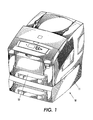
- FIGURE 1 is a perspective view of a printing device having a sheet feeder and separator assembly
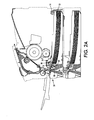
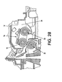
- FIGURE 2a is a cross-sectional view of the printing device of Figure 1 showing a pick module assembly, a removable print media tray and a retard roller assembly;
- FIGURE 2b is an enlarged partial cross-sectional view of the printing device of Figure 2a;
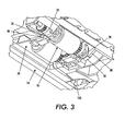
- FIGURE 3 is a partial perspective view of the pick module assembly operatively connected to a frame of the printing device;
- FIGURE 4 is a perspective view of the pick module assembly shown removed from the frame of the printing device and having a pair of flexible bearings;
- FIGURE 5 is a perspective view of the pick module assembly and an actuator arm assembly for maintaining the pick module assembly in an operative position and selectively releasing the pick module assembly for removal from the frame;
- FIGURE 6 is a partial perspective view of the print media tray and the retard roller assembly
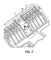
- FIGURE 7 is an enlarged partial perspective view of the print media tray shown with a retard roller of the retard roller assembly removed;
- FIGURE 8a is a partial cross-sectional view of the frame and the pick module assembly shown in a semi-engaged position
- FIGURE 8b is a partial cross-sectional view of the frame and the pick module assembly shown in an operatively engaged position
- FIGURE 8c is a partial elevational view of an axially extending portion of one of the flexible bearings on a pick shaft of the pick module assembly;
- FIGURE 9a is a partial view of the actuator arm assembly and the pick module assembly showing the pick module assembly in the semi-engaged position and ready for full installation into the frame;
- FIGURE 9b is a partial view of the actuator arm assembly and the pick module assembly showing the pick module assembly initially engaging the actuator arm assembly;
- FIGURE 9c is a partial view of the actuator arm assembly and the pick module assembly showing the pick module assembly pivoting the actuator arm assembly;
- FIGURE 9d is a partial view of the actuator arm assembly and the pick module assembly showing the pick module assembly in the operative, engaged position and locked therein by the actuator arm assembly;
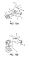
- FIGURE 10a is a partial view of the actuator arm assembly and the pick module a ssembly showing where a force is to be applied on the actuator arm assembly to unlock the pick module assembly;
- FIGURE 10b is a partial view of its actuator arm assembly and the pick module assembly showing the pick module assembly in the semi-engaged position and ready for removal from the frame.
- a printer device is shown in Figure 1 and generally designated by reference numeral 10.
- the printer device 10 is shown as including or being positioned on an auxiliary high capacity feeder 11.
- the printer device 10 includes a sheet feeder and separator assembly for separating and sequentially feeding individual print media sheets from a stack of print media sheets.
- the high capacity feeder 11 also includes a sheet feeder and separator assembly which is substantially similar to that of the printer device 10 and, for this reason, only the feeder and separator assembly of the printer device 10 will be described in further detail.
- the printer device 10 includes a removable print media tray 12 that is suitable for receiving a stack of print media sheets, such as various grades of paper, transparencies or the like.
- the sheet feeder and separator assembly is able to pull a single sheet from the stack of print media sheets held by the print media tray 12 and deliver the single sheet further into the printer device for printing thereon. After a first sheet is fed further into the printer device, subsequent sheets can be sequentially fed one at a time.
- the removable print media tray 12 is carried by a frame 14 of the printer device.
- the tray 12 is a drawer-type tray that slides into a front of the printer device 10 on one or more tracks connected to or defined by the frame 14.
- the frame 14 is constructed of a substantially rigid material such as Noryl® (modified PPO) (Polyphenylene Oxide) which is known to have relatively good electrical insulating properties and dimensional stability.
- a replaceable pick module assembly 16 is removably connected to the frame 14 adjacent the tray 12 as will be described in more detail below.
- the pick module assembly 16 also referred to herein as a customer replaceable unit, includes a first or pick roller 18 and a second or nudger roller 20.
- a separator 22 is connected to the tray 12 such that when the tray is fully inserted into the printer device 10, the separator is positioned adjacent or close to the pick module assembly 16. More particularly, the pick module assembly 16 and the pick roller 18 are positioned adjacent to the separator 22 such that the pick roller 18 and the separator form a nip for receiving single or multiple sheets of print media therein.
- the nudger roller 20 is positioned inwardly of pick roller 18 and together the pick roller 18, the nudger roller 20 and the separator 22 are able to pick a single print media sheet from a stack of print media sheets carried in the tray 12 while retarding all other sheets other than the single, selected sheet.
- the single sheet can then be fed between the separator 22 and the pick roller 18 and delivered further into the printer device 10 for further processing or printing thereon.
- the frame 14 defines a pick module recess 24 for receiving the pick module assembly 16.
- the pick module assembly 16 includes flexible connecting members which, in the illustrated embodiment, are a pair of bearings: first flexible bearing 30 and second flexible bearing 32.
- the bearings 30,32 are removably received in respective first and second bearing recesses 34,36 which are positioned adjacent the pick module recess 24 to removably connect the pick module assembly 16 to the frame 14.
- Due to the rigidity of the frame 14, the wall structures 38,40 of the frame 14 that define the bearing recesses 34,36 substantially resist deformation and are substantially inflexible when the bearings 30,32 are inserted or removed from the recesses 34,36.
- the pick module assembly 16 includes a pick frame 46 to which the pick roller 18 and the nudger roller 20 are rotatably mounted adjacent one another.
- the assembly 16 further includes a pick roller shaft 48 rotatably mounted to the pick frame 46 by the bearings 30,32.
- the pick roller 18 is connected to the pick roller shaft 48 and, more specifically, includes a hub 50, a one-way bearing (not shown) connecting the hub 50 to the shaft 48 and a frictional roller tread 52 fixed to the hub 50.
- the one-way bearing rotatably fixes the pick roller 18 to the shaft 48 when the shaft is rotated in a first direction (clockwise in Figure 4) and rotatably connects the pick roller 18 to the shaft when the shaft 48 is rotated in an opposite, second direction (counterclockwise in Figure 4).
- the pick roller could be an integral part of the pick shaft.
- Such an arrangement could necessitate (for example with a solenoid or a cam) lifting the nudger roller 20 off a stack of media sheets after a single sheet from the stack has moved into the nip between the integrally molded pick roller and the separator 22 to prevent multiple sheets from being forced into the nip each time a single sheet is attempted to be picked from the stack.
- This alternate arrangement should be considered within the scope of the embodiment(s) herein described.
- the nudger roller 20 is rotatably connected to the pick frame 46 by a nudger shaft 54 which is positioned adjacent the pick roller 18. More specifically, the nudger shaft 54 is rotatably received and held in pick frame recesses 56 formed as part of the pick frame 46. Like the pick roller 18, the nudger roller 20 is connected to the nudger shaft 54 and, more specifically, includes a hub 58, a one-way bearing (not shown) connecting the hub 58 rotatably to the shaft 54 and a frictional roller tread 60 fixed to the hub 58.
- this one-way bearing rotatably fixes t he n udger roller 2 0 to the shaft 54 w hen t he s haft i s rotated in the first direction (clockwise in Figure 4) and rotatably connects the nudger roller 20 to the shaft 54 when the shaft 54 is rotated in the opposite second direction (counterclockwise in Figure 4).
- the nudger roller 20 could be an integral part of the shaft 54.
- the one-way bearing of the nudger roller 20 ensures that when a sheet gets pulled past the rollers 18,20, only the hub 58 and tread 60 of the nudger roller 20 rotate therewith. Without the one way bearing, it is likely that the nudger roller 20 would not rotate at all due to the high frictional and inertia forces.
- the nudger roller shaft 54 is connected to the pick roller shaft 48 for rotation therewith such that rotation of the pick roller shaft 54 causes simultaneous rotation of the nudger roller shaft 48. More specifically, a pick roller gear 66 is rotatably fixed to the pick roller shaft 48. Likewise, a nudger roller gear 68 is rotatably fixed to the nudger roller shaft 54. An idler gear 70 is rotatably mounted to the pick frame 46 between the pick roller gear 66 and the nudger roller gear 68.
- Teeth of the idler gear 70 mesh with teeth of the pick roller gear 66 and the nudger roller gear 68 such that the idler gear 70 is engaged to both gears 66,68 so that rotation of the pick roller shaft 48 rotates the pick roller gear which rotates the nudger roller shaft 54 through the idler gear 70 and the nudger roller gear 68.
- a driven gear 72 is fixed to one end of the pick roller shaft 48 and positioned within the printer device 10 for selective engagement with an associated drive gear (not shown). Through a power means such as a motor (not shown), the associated drive gear is positioned to selectively rotate the driven gear 72 and, as described above, the pick and nudger rollers 18,20.
- the sheet feeder and separator assembly further includes an actuator assembly 74 positioned adjacent the pick module assembly 16 in the frame 14.
- the actuator assembly 74 includes an arm 76 that is pivotally connected or mounted to the frame 14 ( Figure 3). More particularly, the arm 76 is integrally formed with an actuator shaft 78 that is rotatably connected to the frame 14 adjacent ends of the shaft 78.
- the arm 76 includes a fork 80 that engages an extending member 82 ( Figure 4) of the pick frame 46 when the pick module assembly 16 is connected to the frame 14 and in an operative position.
- the actuator assembly 74 further includes a biasing means, such as spring 84, that urges the actuator shaft 78 and, in turn, the actuator arm 76 to rotate in an actuator arm first direction (counterclockwise in Figure 5).
- the frame 14 limits how far the arm 76 is able to rotate in the arm first direction.
- the biasing means could be any other device that would urge the arm 76 to rotate in the actuator arm first direction.
- the arm 76 or the extending member 82 could be constructed of a resilient or flexible material and pivoting of the arm 76 could be eliminated for purposes of engaging the arm 76 and the extending member 82.
- the tray 12 includes the separator 22 and a lift plate 86 that raises a stack of print media carried in the tray 12 toward the sheet feeder and separator assembly.
- the separator 22 is a retard roller assembly removably connected to the tray 12 which allows for replacement thereof.
- the retard roller assembly includes a bracket 88 and a retard roller 90 rotatably mounted to the bracket 88.
- the retard roller 90 includes a hub 92 having axial projections rotatably connected to the bracket 88 and a frictional roller tread 94 rotatably fixed to the hub 92.
- the retard roller 90 and bracket 88 are received within a retard recess 96 defined in the tray 12.
- a bias means such as spring 98
- spring 98 is connected to the tray 12 for urging the retard roller 90 into the pick roller 18 when assembled in the printer device 10.
- the spring 98 is received in a spring recess 100 and can be automatically retained by a snap tab feature during installation of the retard roller and bracket assembly. During replacement of the retard roller and bracket assembly, the spring can be threadedly disengaged from the tray's snap tab feature 12 within the recess 100 for easy removal from the tray 12. The spring 98 assists in providing a nip force between the retard roller 90 and the pick roller 18.
- the bracket 88 includes recesses defined by flexible fingers (not shown) that engage or snap-on to the shaft projections 102 defined by the tray 12.
- the hub 92 is connected to the bracket 88 by a retard shaft (not shown) and a retard wrap spring (not shown).
- the shaft is made of plastic to reduce manufacturing costs.
- the shaft removably connects to the bracket 88 by snapping into recesses or grooves (not shown) of the bracket 88 which enables relatively easy replacement of the entire retard roller assembly or just the shaft, hub 92 and tread 94 independent of the bracket 88. More specifically, the retard shaft is nonrotatably fixed to the retard bracket 88.
- the hub 92 is rotatably connected to the shaft with the retard wrap spring.
- the retard wrap spring provides a constant drag when the retard roller 90 is forced to rotate - for example directly by the pick roller 18 or by a sheet of print media in the nip.
- the retard roller 90 is able to prevent more than a single sheet of print media from being picked up because a retard torque (or drag torque) developed by the wrap spring causes a separation force higher than the force that keeps two or more sheets of the print media together.
- the retard spring winds up slightly when providing the drag torque.
- the retard spring releases and kicks any other sheets out of the nip. Therefore, the retard roller acts as an active driven retard roller without being driven as a result of the wrap spring.
- the use of a retard spring to urge the retard roller 90 toward the pick roller 18 classifies the retard roller assembly of the illustrated embodiment as having a semi-active retard roller.
- the retard roller assembly could be modified or substituted for a variety of other known retard roller assemblies.
- an active retard roller could be used in place of the illustrated and described semi-active retard roller 90.
- An active retard roller could necessitate the use of a more complicated mechanism to transmit torque to the retard roller but could also allow for improved separation reliability of the sheets of print media.
- a separator pad could be used in place of the retard roller assembly. The use of the separator pad could reduce the complexity of the separator but may result in reduced separation reliability for the sheets of print media.
- the separator 22 is independent of the pick module assembly 16 and can be replaced independently of the pick module assembly 16.
- the pick module assembly 16 is shown in a partially or semi-engaged position wherein the first bearing 30 is shown received in the first recess 34 of the frame 14.
- the bearing 30 has an adjustable or compressible diameter that allows the bearing 30 to be removed from and, if desirable, reinstalled into the bearing recess 34.
- the pick module assembly 16 is shown in the operative position wherein the bearing 30 is received in the first recess 34 of the frame 14 and, with additional reference to Figure 9d, the extending member 82 is engaged by the fork 80 of the actuator arm 76 locking the pick module assembly 16 in the operative position.
- the bearing 30 has a constant or non-compressible diameter which prevents the bearing 30 from being removed from the recess 34 and substantially prevents transverse movement of the pick module assembly 16 relative to the bearing recess 34.
- both flexible bearings 30,32 are substantially similar and only one will be discussed in further detail.
- the bearing 30 has a diameter or first dimension A that is variable, flexible and/or adjustable along a first axis or direction B.
- the bearing has another diameter or second dimension C that is constant, rigid and/or relatively inflexible along a second axis or direction D.
- the second axis D is angularly offset relative to the first axis B. More particularly, in the illustrated embodiment, the second axis D is approximately normal to the first axis B.
- the shape of bearing 30 in the illustrated embodiment is circular, it should be understood that the shape of the bearings could be modified or substituted for and all such modifications or substitutions are to be considered within the scope of the described embodiment.
- the bearings could have a solid double D or oval shape.
- the bearing 30 includes a grooved portion 108 which is received within a bearing recess 110 of the pick frame 46 to connect the bearing 30 to the pick frame 46.
- a pair of spaced wall portions 112,114 are axially disposed or positioned in the grooved portion 108 of the bearing 30 to limit relative rotation of the bearing 30 within the bearing recess 110.
- an axially extending portion is adjacent the grooved portion 108 and includes opposed radial portions 116,118 adjacent the pick roller shaft 48 that have a substantially fixed diameter thereacross and opposed fingers 120,122 extending from the radial portions 116,118 and radially spaced from the pick roller shaft 48.
- the opposed fingers 120,122 have a flexible, varying diameter thereacross. Further, the fingers 120,122 extend radially from the radial portions 116,118 and are axially spaced from the grooved portion 108 of the bearing 30. This arrangement allows the fingers 120,122 to flex or bend which thereby allows the diameter across the fingers to vary.
- the first bearing recess 34 is shown with the first flexible bearing 30 removably connected thereto.
- the recess 34 has an opening width E that is smaller than the diameter of the bearing. Because the frame 14 defining the recess 34 is rigid and substantially inflexible, the bearing diameter has to be variable to allow for insertion and removal of the bearing 30. More particularly, to install and remove the bearing 30 from the recess 34, the variable first dimension A of the bearing 30 is generally aligned with the opening width E of the bearing recess 34 as shown in Figure 8a. Thus, the first axis B of the bearing is aligned with the opening width E which positions the fingers 120,122 on either side of the recess.
- the bearing 30 can flex for removal from and insertion into the bearing recess 34.
- the assembly 16 is pulled straight away from the bearing recess 34 which allows the fingers 120,122 to flex and permit removal.
- the fingers 120,122 are aligned with the recess 34 as shown in Figure 8a and the pick module assembly is pushed straight into the bearing recess 34.
- the pick module assembly is shown in an operative position.
- the pick module assembly 16 is rotated (counterclockwise from Figure 8a to Figure 8b) until the radial portions 116,118 are aligned with the sides of the bear recess 34 as shown in Figure 8c.
- the radial portions 116,118 fill across the bearing recess 34 and prevent removal of the pick module assembly until the first dimension A of the bearing 30 is again aligned with the opening width E.
- the radial portions 116,118 fix the position and substantially prevent movement of the pick module assembly along the axis D relative to the frame when in the operative position.
- the pick module assembly 16 is locked to the frame 14 until the pick module assembly is rotated so that the first dimension A or first axis B is parallel or aligned with the opening width E.
- the pick module assembly is rotated further about the bearings into the actuator arm 76 against the urging of the spring 84, i.e., a force is applied on the pick module assembly 16 that overcomes the urging of the spring 84, thereby pivoting the actuator arm 76 toward an actuator arm second position.
- the extending member 82 passes a short arm 124 of the fork 80 and the spring 84 causes the fork 80 to snap onto the extending member 82.
- the spring 84 urges the actuator arm 76 back toward the arm first position and the pick module assembly is urged to rotate about the bearings 30,32.
- the actuator arm 76 In addition to maintaining the pick module assembly 16 in the operative position, the actuator arm 76 also controls the radial position of the pick module assembly 16 relative to the bearings 30,32. More particularly, the urging of the pick module assembly 16 about the bearings 30,32 by the spring (clockwise in Figure 9d) urges or biases the nudger roller toward an associated stack of print media carried in the tray 12.
- the tray 12 can be loaded with a stack of print media and inserted in the frame 14.
- the printer device 10 senses that the tray 12 has been inserted it turns on the lift motor (not shown), raising the lift plate 86 and the associated stack of media.
- the uppermost sheet of the associated stack of print media contacts the nudger roller 20 of the pick module assembly 16 and rotates the pick module assembly 16 slightly about the bearings 30,32.
- the extending member 82 which is captured by the actuator fork 80, rotates the actuator arm 76 when the engagement of the print media causes the pick module assembly 16 to rotate.
- a flag 128 on the arm 76 actuates a sensor (not shown) connected to the frame 14 indicating to the printer device that the media has reached the correct height for feeding and that the lift motor can be turned off.
- the driven gear 72 is driven by the associated drive gear which rotates the rollers 18,20.
- the nudger roller 20 moves the top sheet from the stack so that the leading edge enters the nip formed by the pick roller 18 and the separator 22.
- the pick roller then drives the sheet of media up into the print device 10 for printing. If multiple sheets attempt to enter the nip, they are separated by the separator so that only a single sheet will be fed past the nip.
- Removal of the pick module assembly 16 may be desirable if the pick module assembly is to be replaced such as may be necessary when either or both of the treads 52,60 wear out.
- a user To remove the pick module assembly 16 from the frame 14, a user first removes the media tray 12 to gain access to the underside of the pick module assembly 16. A user then applies a force to the actuator arm 76 to pivot the arm against the urging of the spring 84. More particularly, with reference to Figures 3 and 10a, the actuator assembly includes an actuator arm release lever 126 connected to the arm 76. A force is applied to the release lever 126 in the direction of arrow F which pivots the arm 76 toward the arm second position against the urging of the spring 84 and pivots the pick module assembly 16 about the bearings 30,32.
- the extending member 82 disengages from the fork 80 of the arm 76 and gravity causes the pick module assembly 16 to rotate away from the arm 76 (clockwise in Figure 10a). More specifically, gravity causes the pick module assembly 16 to move to the semi-engaged position.
- the bearings 30,32 are aligned so that the pick module assembly 16 can be readily disconnected from the frame 14.
- the nudger roller 20 hangs below the pick roller 18 permitting a user a portion of the assembly 16 that is easily graspable and able to be used to pull the assembly 16 from the frame 14. The user then pulls straight down on the pick module assembly 16 to disconnect it from the frame 14.
- the relatively easy removability of the pick module assembly 16 enables a user to be able to relatively easily replace the pick module assembly when desired.
- the user holds the pick module assembly 16 in a vertical orientation (i.e., with the pick roller 18 above the nudger roller 20), and pushes it up into the bearing recesses 34,36 of the frame 14.
- the flexible bearings 30,32 on the pick module assembly 16 allow the assembly to snap into and connect to the rigid printer frame 14 as described above.
- the user then pushes on the nudger roller 20 to rotate the pick module assembly 16 up into the recess 24 in the frame 14.
- the extending member or pin 82 contacts the underside of the actuator arm fork 80.
- the user must continue to rotate the nudger roller 20 up far enough so that the pick module assembly 16 rotates past a horizontal position and the pin 82 slides past the lower part of the actuator arm fork 80 and engages into the fork 80. The user then reinserts the media tray 12.
Landscapes
- Engineering & Computer Science (AREA)
- Mechanical Engineering (AREA)
- Sheets, Magazines, And Separation Thereof (AREA)
- Mounting Of Bearings Or Others (AREA)
Applications Claiming Priority (2)
| Application Number | Priority Date | Filing Date | Title |
|---|---|---|---|
| US10/753,606 US7025345B2 (en) | 2004-01-08 | 2004-01-08 | Replacement method and assembly for paper pick rollers |
| US753606 | 2004-01-08 |
Publications (2)
| Publication Number | Publication Date |
|---|---|
| EP1553032A1 true EP1553032A1 (fr) | 2005-07-13 |
| EP1553032B1 EP1553032B1 (fr) | 2009-09-09 |
Family
ID=34592579
Family Applications (1)
| Application Number | Title | Priority Date | Filing Date |
|---|---|---|---|
| EP05000163A Expired - Lifetime EP1553032B1 (fr) | 2004-01-08 | 2005-01-05 | Méthode de remplacement améliorée et dispositif à rouleaux d'alimentation de papier |
Country Status (4)
| Country | Link |
|---|---|
| US (1) | US7025345B2 (fr) |
| EP (1) | EP1553032B1 (fr) |
| JP (1) | JP4773100B2 (fr) |
| DE (1) | DE602005016472D1 (fr) |
Cited By (1)
| Publication number | Priority date | Publication date | Assignee | Title |
|---|---|---|---|---|
| EP1798170A1 (fr) * | 2005-12-19 | 2007-06-20 | MEI, Inc. | Unité de distribution pour documents de valeur |
Families Citing this family (13)
| Publication number | Priority date | Publication date | Assignee | Title |
|---|---|---|---|---|
| JP2008133079A (ja) * | 2006-11-28 | 2008-06-12 | Kyocera Mita Corp | シート給送装置 |
| JP2008133078A (ja) * | 2006-11-28 | 2008-06-12 | Kyocera Mita Corp | シート給送装置 |
| JP4740293B2 (ja) * | 2008-04-24 | 2011-08-03 | 株式会社沖データ | 給紙装置および画像形成装置 |
| JP2010038290A (ja) * | 2008-08-06 | 2010-02-18 | Ntn Corp | リユース軸受およびそのリユース方法 |
| FR2964375B1 (fr) * | 2010-09-08 | 2013-05-17 | Sidel Participations | Table d'injection d'un film plastique pour fardeleuse |
| JP5733177B2 (ja) * | 2011-11-28 | 2015-06-10 | ブラザー工業株式会社 | 画像形成装置 |
| US8861051B1 (en) * | 2013-08-14 | 2014-10-14 | Foxlink Image Technology Co., Ltd. | Roller assembly |
| JP5636077B2 (ja) * | 2013-08-27 | 2014-12-03 | 京セラドキュメントソリューションズ株式会社 | シート搬送装置及び、これを備えた原稿搬送装置並びに画像形成装置 |
| US9617091B2 (en) * | 2014-06-03 | 2017-04-11 | Canon Kabushiki Kaisha | Feeding device and image forming device |
| EP3032142A1 (fr) * | 2014-12-11 | 2016-06-15 | Canon Kabushiki Kaisha | Dispositif de transmission d'entraînement pour entraînement rotatif |
| JP6424838B2 (ja) * | 2016-01-07 | 2018-11-21 | 京セラドキュメントソリューションズ株式会社 | シート給送装置、及びシート給送装置を備える画像形成装置 |
| JP7379047B2 (ja) * | 2019-09-27 | 2023-11-14 | キヤノン株式会社 | シート給送装置、及び画像形成装置 |
| JP2025107922A (ja) * | 2024-01-09 | 2025-07-22 | ブラザー工業株式会社 | シート給送装置 |
Citations (5)
| Publication number | Priority date | Publication date | Assignee | Title |
|---|---|---|---|---|
| EP0296820A2 (fr) * | 1987-06-26 | 1988-12-28 | Xerox Corporation | Appareil d'avancement de feuilles |
| US5709380A (en) * | 1995-08-16 | 1998-01-20 | Xerox Corporation | Replaceable compact feed roll unit |
| US5769410A (en) * | 1996-09-19 | 1998-06-23 | Xerox Corporation | Lift and drive actuators for feeder CRU |
| JP2000203728A (ja) * | 1999-01-11 | 2000-07-25 | Canon Inc | シ―ト材給送装置及び画像形成装置 |
| US20020190460A1 (en) * | 2001-06-13 | 2002-12-19 | Glenn Gaarder | Sheet feeder with modular roller support and drive assembly |
Family Cites Families (22)
| Publication number | Priority date | Publication date | Assignee | Title |
|---|---|---|---|---|
| CH661478A5 (de) * | 1983-11-15 | 1987-07-31 | Kurt Ruenzi | Vorrichtung zum vereinzeln und zum einzug von blaettern in eine bueromaschine. |
| JPS63109029A (ja) * | 1986-10-27 | 1988-05-13 | Canon Inc | 光デイスク基板の製造用金型 |
| JPS64111A (en) | 1987-06-23 | 1989-01-05 | Mitsubishi Petrochem Co Ltd | Surface modification of polymeric material |
| JPH0270634A (ja) * | 1988-09-01 | 1990-03-09 | Konica Corp | 給紙装置 |
| JPH0332216A (ja) * | 1989-06-29 | 1991-02-12 | Nec Corp | フィルタ回路 |
| JPH04148749A (ja) * | 1990-10-09 | 1992-05-21 | Matsushita Electric Ind Co Ltd | 画像読取装置 |
| GB2259909B (en) * | 1991-09-11 | 1995-10-18 | Xerox Corp | Sheet feed apparatus |
| JP3193165B2 (ja) * | 1992-11-13 | 2001-07-30 | 株式会社リコー | 給紙装置 |
| JP3198764B2 (ja) * | 1993-12-09 | 2001-08-13 | 村田機械株式会社 | 原稿分離装置 |
| US5421569A (en) | 1994-10-12 | 1995-06-06 | Xerox Corporation | Replaceable feed/retard roll unit |
| US5720478A (en) * | 1996-09-26 | 1998-02-24 | Xerox Corporation | Gateless duplex inverter |
| JPH10244717A (ja) * | 1997-03-07 | 1998-09-14 | C B M Kk | サーマルプリンタ |
| US5921539A (en) * | 1997-03-26 | 1999-07-13 | Eastman Kodak Company | Sheet feeding device |
| US6173951B1 (en) * | 1997-09-01 | 2001-01-16 | Brother Kogyo Kabushiki Kaisha | Sheet feeder for feeding one sheet at a time from sheet stack regardless of thickness and weight of sheets |
| US6325560B1 (en) * | 1998-02-05 | 2001-12-04 | Canon Business Machines, Inc. | Wide format printer with detachable and replaceable paper feed unit components |
| JP2000016624A (ja) * | 1998-06-30 | 2000-01-18 | Canon Inc | シート給送装置及びこの装置を備えた画像形成装置 |
| JP3220940B2 (ja) * | 1998-09-11 | 2001-10-22 | 株式会社田村電機製作所 | フランジ付軸受の取付構造 |
| US6059279A (en) * | 1998-09-14 | 2000-05-09 | Xerox Corporation | Retard sheet separator-feeder with retarded sheets kickback reduction |
| IT1307034B1 (it) * | 1999-04-12 | 2001-10-23 | Olivetti Lexikon Spa | Dispositivo per l'alimentazione di fogli da una risma del tipocomprendente un rullo principale di avanzamento ed un rullo |
| ATE416748T1 (de) * | 1999-05-21 | 2008-12-15 | Cochlear Ltd | Elektrodenmatrix für cochlea-implantat |
| JP2002053237A (ja) * | 2000-05-29 | 2002-02-19 | Ricoh Co Ltd | 給紙装置 |
| US6666446B2 (en) * | 2001-06-13 | 2003-12-23 | Hewlett-Packard Development Company, L.P. | Replaceable roller bogie for document feeding apparatus |
-
2004
- 2004-01-08 US US10/753,606 patent/US7025345B2/en not_active Expired - Fee Related
-
2005
- 2005-01-05 DE DE602005016472T patent/DE602005016472D1/de not_active Expired - Lifetime
- 2005-01-05 EP EP05000163A patent/EP1553032B1/fr not_active Expired - Lifetime
- 2005-01-11 JP JP2005003361A patent/JP4773100B2/ja not_active Expired - Fee Related
Patent Citations (5)
| Publication number | Priority date | Publication date | Assignee | Title |
|---|---|---|---|---|
| EP0296820A2 (fr) * | 1987-06-26 | 1988-12-28 | Xerox Corporation | Appareil d'avancement de feuilles |
| US5709380A (en) * | 1995-08-16 | 1998-01-20 | Xerox Corporation | Replaceable compact feed roll unit |
| US5769410A (en) * | 1996-09-19 | 1998-06-23 | Xerox Corporation | Lift and drive actuators for feeder CRU |
| JP2000203728A (ja) * | 1999-01-11 | 2000-07-25 | Canon Inc | シ―ト材給送装置及び画像形成装置 |
| US20020190460A1 (en) * | 2001-06-13 | 2002-12-19 | Glenn Gaarder | Sheet feeder with modular roller support and drive assembly |
Non-Patent Citations (1)
| Title |
|---|
| PATENT ABSTRACTS OF JAPAN vol. 2000, no. 10 17 November 2000 (2000-11-17) * |
Cited By (4)
| Publication number | Priority date | Publication date | Assignee | Title |
|---|---|---|---|---|
| EP1798170A1 (fr) * | 2005-12-19 | 2007-06-20 | MEI, Inc. | Unité de distribution pour documents de valeur |
| US7726645B2 (en) | 2005-12-19 | 2010-06-01 | Mei, Inc. | Dispensing value sheet store |
| US8419011B2 (en) | 2005-12-19 | 2013-04-16 | Mei, Inc. | Dispensing value sheet store |
| US8448939B2 (en) | 2005-12-19 | 2013-05-28 | Mei, Inc. | Dispensing value sheet store |
Also Published As
| Publication number | Publication date |
|---|---|
| DE602005016472D1 (de) | 2009-10-22 |
| JP4773100B2 (ja) | 2011-09-14 |
| JP2005194099A (ja) | 2005-07-21 |
| US20050151312A1 (en) | 2005-07-14 |
| EP1553032B1 (fr) | 2009-09-09 |
| US7025345B2 (en) | 2006-04-11 |
Similar Documents
| Publication | Publication Date | Title |
|---|---|---|
| US7025345B2 (en) | Replacement method and assembly for paper pick rollers | |
| US8123212B1 (en) | Method and apparatus for adjusting media positioning and indexing using an encoder in an image forming device | |
| US6666446B2 (en) | Replaceable roller bogie for document feeding apparatus | |
| US20040207145A1 (en) | Paper-feeding apparatus of an image forming apparatus | |
| US8210521B2 (en) | Method for feeding compressible media in an image forming device | |
| US8167300B1 (en) | Method for determining the amount of media sheets in a media tray in an image forming device | |
| US20020190458A1 (en) | Roller gear over engagement protection for document feeder | |
| US6651973B2 (en) | Sheet feeder with modular roller support and drive assembly | |
| US7431284B2 (en) | Sheet transfer apparatus | |
| JP2020121872A (ja) | シート搬送装置及び画像形成装置 | |
| US8833757B1 (en) | Method of using separator roll positioner in a removable media dam and separator roll speed to correct feed errors | |
| US6764072B2 (en) | Sheet feeder roller assembly with stack damper | |
| JP2019059559A (ja) | シート搬送装置及び画像形成装置 | |
| JP2001328734A (ja) | 給紙装置及びこれを用いた印刷装置 | |
| US8256762B2 (en) | Raisable lift plate system for positioning and feeding media in an image forming device | |
| US8944428B2 (en) | Removable media dam with separator roll positioner for a media tray | |
| US8020850B1 (en) | Removable input tray assembly having a dual function roller for feeding media and separating media in an image forming device | |
| US9446919B2 (en) | Push-pull latch assembly for a detachable media pick mechanism | |
| US20070132173A1 (en) | Paper-releasing mechanism | |
| US8025283B1 (en) | Continuous media edge reference surface for a removable media input tray assembly of an image forming device | |
| JP2547978B2 (ja) | シート材給送装置 | |
| US20120104683A1 (en) | System for Feeding and Separating Media in an Image Forming Device | |
| JP2009269696A (ja) | シート給送装置及び画像形成装置 | |
| US8267393B1 (en) | Continuous media edge reference surface for a removable media input tray assembly of an image forming device | |
| JP2005015174A (ja) | 給紙装置 |
Legal Events
| Date | Code | Title | Description |
|---|---|---|---|
| PUAI | Public reference made under article 153(3) epc to a published international application that has entered the european phase |
Free format text: ORIGINAL CODE: 0009012 |
|
| AK | Designated contracting states |
Kind code of ref document: A1 Designated state(s): AT BE BG CH CY CZ DE DK EE ES FI FR GB GR HU IE IS IT LI LT LU MC NL PL PT RO SE SI SK TR |
|
| AX | Request for extension of the european patent |
Extension state: AL BA HR LV MK YU |
|
| 17P | Request for examination filed |
Effective date: 20060113 |
|
| AKX | Designation fees paid |
Designated state(s): DE FR GB |
|
| 17Q | First examination report despatched |
Effective date: 20070531 |
|
| GRAP | Despatch of communication of intention to grant a patent |
Free format text: ORIGINAL CODE: EPIDOSNIGR1 |
|
| GRAS | Grant fee paid |
Free format text: ORIGINAL CODE: EPIDOSNIGR3 |
|
| GRAA | (expected) grant |
Free format text: ORIGINAL CODE: 0009210 |
|
| AK | Designated contracting states |
Kind code of ref document: B1 Designated state(s): DE FR GB |
|
| REG | Reference to a national code |
Ref country code: GB Ref legal event code: FG4D |
|
| REF | Corresponds to: |
Ref document number: 602005016472 Country of ref document: DE Date of ref document: 20091022 Kind code of ref document: P |
|
| PLBE | No opposition filed within time limit |
Free format text: ORIGINAL CODE: 0009261 |
|
| STAA | Information on the status of an ep patent application or granted ep patent |
Free format text: STATUS: NO OPPOSITION FILED WITHIN TIME LIMIT |
|
| 26N | No opposition filed |
Effective date: 20100610 |
|
| REG | Reference to a national code |
Ref country code: FR Ref legal event code: PLFP Year of fee payment: 12 |
|
| REG | Reference to a national code |
Ref country code: FR Ref legal event code: PLFP Year of fee payment: 13 |
|
| PGFP | Annual fee paid to national office [announced via postgrant information from national office to epo] |
Ref country code: GB Payment date: 20161228 Year of fee payment: 13 |
|
| PGFP | Annual fee paid to national office [announced via postgrant information from national office to epo] |
Ref country code: FR Payment date: 20161221 Year of fee payment: 13 |
|
| PGFP | Annual fee paid to national office [announced via postgrant information from national office to epo] |
Ref country code: DE Payment date: 20161219 Year of fee payment: 13 |
|
| REG | Reference to a national code |
Ref country code: DE Ref legal event code: R119 Ref document number: 602005016472 Country of ref document: DE |
|
| GBPC | Gb: european patent ceased through non-payment of renewal fee |
Effective date: 20180105 |
|
| PG25 | Lapsed in a contracting state [announced via postgrant information from national office to epo] |
Ref country code: DE Free format text: LAPSE BECAUSE OF NON-PAYMENT OF DUE FEES Effective date: 20180801 Ref country code: FR Free format text: LAPSE BECAUSE OF NON-PAYMENT OF DUE FEES Effective date: 20180131 |
|
| REG | Reference to a national code |
Ref country code: FR Ref legal event code: ST Effective date: 20180928 |
|
| PG25 | Lapsed in a contracting state [announced via postgrant information from national office to epo] |
Ref country code: GB Free format text: LAPSE BECAUSE OF NON-PAYMENT OF DUE FEES Effective date: 20180105 |