EP1553233A1 - Bouche d'égout - Google Patents
Bouche d'égout Download PDFInfo
- Publication number
- EP1553233A1 EP1553233A1 EP04292916A EP04292916A EP1553233A1 EP 1553233 A1 EP1553233 A1 EP 1553233A1 EP 04292916 A EP04292916 A EP 04292916A EP 04292916 A EP04292916 A EP 04292916A EP 1553233 A1 EP1553233 A1 EP 1553233A1
- Authority
- EP
- European Patent Office
- Prior art keywords
- frame
- grid
- bars
- adjacent
- roadway
- Prior art date
- Legal status (The legal status is an assumption and is not a legal conclusion. Google has not performed a legal analysis and makes no representation as to the accuracy of the status listed.)
- Granted
Links
- XLYOFNOQVPJJNP-UHFFFAOYSA-N water Substances O XLYOFNOQVPJJNP-UHFFFAOYSA-N 0.000 claims abstract description 34
- 230000002441 reversible effect Effects 0.000 description 3
- 230000000284 resting effect Effects 0.000 description 1
- 230000000717 retained effect Effects 0.000 description 1
- 239000003643 water by type Substances 0.000 description 1
Images


Classifications
-
- E—FIXED CONSTRUCTIONS
- E03—WATER SUPPLY; SEWERAGE
- E03F—SEWERS; CESSPOOLS
- E03F5/00—Sewerage structures
- E03F5/04—Gullies inlets, road sinks, floor drains with or without odour seals or sediment traps
- E03F5/06—Gully gratings
-
- E—FIXED CONSTRUCTIONS
- E03—WATER SUPPLY; SEWERAGE
- E03F—SEWERS; CESSPOOLS
- E03F5/00—Sewerage structures
- E03F5/04—Gullies inlets, road sinks, floor drains with or without odour seals or sediment traps
- E03F5/06—Gully gratings
- E03F2005/061—Gully gratings hinged to the body of the gully
-
- Y—GENERAL TAGGING OF NEW TECHNOLOGICAL DEVELOPMENTS; GENERAL TAGGING OF CROSS-SECTIONAL TECHNOLOGIES SPANNING OVER SEVERAL SECTIONS OF THE IPC; TECHNICAL SUBJECTS COVERED BY FORMER USPC CROSS-REFERENCE ART COLLECTIONS [XRACs] AND DIGESTS
- Y02—TECHNOLOGIES OR APPLICATIONS FOR MITIGATION OR ADAPTATION AGAINST CLIMATE CHANGE
- Y02A—TECHNOLOGIES FOR ADAPTATION TO CLIMATE CHANGE
- Y02A30/00—Adapting or protecting infrastructure or their operation
- Y02A30/60—Planning or developing urban green infrastructure
Definitions
- the present invention relates to equipment for roadways, such as manholes.
- Such road equipment is known as comprising a generally rectangular frame be incorporated into a roadway, preferably along a sidewalk border delimiting the roadway.
- This frame has on one of its sides, the side adjacent to the curb, hinge elements cooperating with elements articulated on one side of each of the two square grids arranged side by side closing of the frame, each grid having bars parallel inclined in the direction of water flow of runoff along the pavement to absorb water runoff between the bars of the grids.
- This known road equipment has the disadvantage to require two models of square grilles with bars inclined to account for the direction of flow of water runoff along the roadway, that is to say a square grid that can be hinged to the side corresponding support frame so as to steer the bars inclined in a direction of water flow of runoff and another square grid that can be articulated to the side of the frame so that the bars are tilted in the opposite direction of water flow from runoff.
- the present invention aims to eliminate the disadvantages above by proposing equipment for roadway, such as a manhole, comprising a frame quadrilateral form which can be incorporated into a pavement and comprising on one side only hinge elements, and at least one square grid of closing the frame with parallel rungs inclined and first hinge elements to one sides cooperating with those on the side of the frame for allow it to be mounted articulated to this side, and which is characterized in that the grid also comprises second articulation elements arranged at one of the sides of the grid adjacent to the one with the first articulating elements to allow the grid to be mounted hinged to the side of the frame by one or the other of its adjacent sides so that the bars of the grid are inclined relative to the hinge side of the frame in the direction of flow runoff along the roadway for absorb the water between the bars of the grid.
- the equipment includes a second square grid to inclined bars including first and second articulation elements respectively to two of his adjacent sides and able to be articulated by one from its sides adjacent to the hinge side of the rectangle-shaped frame being arranged side by side coast with the first grid so that its bars are inclined in the direction of water flow of runoff along the pavement to absorb water runoff between the bars of the second grid, the bars of the second grid can be parallel or not to those of the first grid following the meaning flow of runoff water arriving at the second wire rack.
- the frame can be installed in curb of a pavement with its side to hinge element adjacent to the curb.
- Road equipment includes a second frame identical to the first frame and can be installed in edge of a sidewalk opposite the pavement and each grid of the second frame can be hinged to the side with hinge elements of the second frame so that its bars are inclined in the direction of flow runoff water arriving at the second frame.
- Road equipment forming a manhole the invention will be described as being installed in curb of a pavement, but it is well heard that it can be installed at any other place of receiving runoff water
- the equipment of Roadway includes two identical square frames 1 incorporated in a pavement C respectively along two opposite sidewalk borders B delimiting the floor.
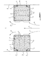
- Each frame 1 has only one of its sides 1a adjacent to the border B provided with articulation elements 2 to which are connected hinge elements 3 located at a side of a square grid 4 with inclined parallel bars 5 to allow grid 4 to rotate around on the side 1a of a closed position of the frame 1 in resting on the latter at a raised position opening of this frame to which grid 4 can be retained in the frame 1 by the articulation elements 2, 3 while allowing its removal from the frame at this position identified.
- each of the two grids opposed squares 4 occupying their closed position frame 1 are oriented in the direction of water flow of runoff along the C roadway and that is symbolized by the arrows F1 so that the water of runoff arriving at both frames 1 may flow and be absorbed freely in the spaces between inclined parallel bars 5 of the two grids 4.
- each grid 4 comprises also at one of its sides adjacent to that articulated at the side 1a of the frame 1 of the articulation elements 3 identical to the hinge elements 3 on the articulated side to the frame 1 so that a grid 4 can be mounted articulated by one of its two sides adjacent to the side 1a of the frame 1 having its inclined bars 5 can be oriented in the direction of flow F1 of the water of runoff.
- the two frames 1 being identical, to install a frame 1 of a sidewalk to another, just rotate it around of its central axis of symmetry of 180 °.
- a grid 4 of the invention can then be articulated to the side of the of each frame 1 by one of its two adjacent sides of way that its bars are oriented according to the direction F1 flow of runoff water.
- FIG. 2 represents a variant embodiment according to which each frame 1 is rectangular having one of its longitudinal sides 1a disposed adjacent to the corresponding sidewalk border B and to which are articulated mounted two identical square grids 4 to inclined bars 5 for closing the frame 1 in being laid side by side on the latter.
- each grid 4 is reversible, that is to say that it contains elements of articulation 3 on two of its adjacent sides of way to mount the hinged grid to the side 1a of the frame 1 according to the desired orientation of the bars inclined 5 taking into account the flow direction of the water of runoff on the roadway C.
- FIG. 2 shows that the inclined bars 5 of two pairs of grids 4 located respectively along two edges B opposite sidewalks are oriented following the direction corresponding to that of F1 flow of runoff water and it is possible for each frame 1, to articulate the two grids 4 to the side 1a of the frame 1 by their free joints 3 of their adjacent sides so that their respective bars 5 are oriented in the direction of flow of water from runoff opposite direction F1 of Figure 2 if the water runoff had to flow on the roadway in the opposite.
- each frame 1 it is also possible for each frame 1 to provide a grid 4 mounted articulated to the side of the frame 1 in a direction corresponding to the meaning F1 flow of runoff water as this is the case in Figure 2, for example, for both grids lower 4 respectively of the two frames 1 and to articulate each of the two upper grids 4 of these frames by rotating 90 ° around its central axis of symmetry of the grid 4 so that the bars 5 of each upper grid 4 are oriented in one direction flow of runoff water opposite that F1.
- FIG. 3 represents a variant embodiment of Figure 2 according to which two rectangular frames 1 are installed on the roadway C in extension one of the other along each sidewalk border B.
- each grid 4 has on two of its sides adjacent articulation elements 3 as in FIG. and can be mounted to the longitudinal side 1a of each frame 1 by one or the other of its adjacent sides according to the flow direction of the runoff water on the C.
- the two grids 4 of each frame 1 located in the upper part of Figure 3 could be oriented differently to reflect a meaning flow different from the runoff water on the C by rotating them 90 ° each of their central axis of symmetry so as to mount them articulated at the side 1a of the frame 1 by the elements 3 of the free adjacent side of each grid.
- two frames rectangular 1 located along a curb B can be joined together by their little ones respective sides 1b transverse to the border B by a tenon 6 integral with one of the walls constituting the side 1b of a frame and a window 7 in which engages the tenon and made through the wall constituting the adjacent side 1b of the other frame 1.
- Figures 4 and 5 represent, by way of example, each articulation, known per se, connecting a grid 4 at the side 1a of the frame 1.
- Each joint 2, 3 comprises a cylindrical axis 8 of a clevis 9 formed at the side corresponding to a grid 4 and a recess 10 formed in through a portion of transverse wall 11 secured on the side 1a of the frame 1 and engaged in the yoke 9.
- the recess 10 has a vertical passage of the axis 8 extended by a horizontal passage to the side 1a of the frame 1 so that in the closed position of the grid 4, the axis 8 is located in the horizontal passage to prevent the lifting of the grid 4 of the framework 1.
- a only reversible grid model allows to adapt it to the pavement, taking into account the flow direction of the water runoff arriving at the frame containing the reversible grids.
- support frameworks grids can be installed differently in the floor.
- each rectangular frame can be oriented transversely to the edge of the sidewalk having one of its short sides adjacent to this border, one of its big sides featuring the elements articulation of each grid.
- the two senior executives can be installed as shown in this figure parallel to their respective sidewalk borders and the two lower frames can be installed perpendicular to these two borders.
Landscapes
- Life Sciences & Earth Sciences (AREA)
- Engineering & Computer Science (AREA)
- Hydrology & Water Resources (AREA)
- Public Health (AREA)
- Water Supply & Treatment (AREA)
- Health & Medical Sciences (AREA)
- Road Paving Structures (AREA)
- Temperature-Responsive Valves (AREA)
- Sewage (AREA)
- Road Signs Or Road Markings (AREA)
- Fertilizing (AREA)
- Secondary Cells (AREA)
- Incineration Of Waste (AREA)
- Duct Arrangements (AREA)
Abstract
Description
- la figure 1 est une vue de dessus d'un équipement de voirie suivant un premier mode de réalisation de l'invention, installé en bordure de deux trottoirs opposés délimitant une chaussée ;
- la figure 2 est une vue de dessus d'un équipement de voirie selon un second mode de réalisation de l'invention ;
- la figure 3 est une vue de dessus de l'équipement de voirie de la figure 2 suivant un troisième mode de réalisation ;
- la figure 4 est une vue agrandie en perspective de la partie cerclée en IV de la figure 3 et représentant un exemple de réalisation d'une articulation d'une grille au cadre de l'équipement de voirie des figures 1 à 3 ;
- la figure 5 est une vue en coupe suivant la ligne V-V de la figure 4 ; et
- la figure 6 est une vue agrandie en perspective de la partie cerclée en VI de la figure 3.
Claims (6)
- Equipement de voirie, tel que bouche d'égout, comprenant un cadre (1) en forme de quadrilatère pouvant être incorporé à une chaussée (C) et comportant sur un seul (1a) de ses côtés des éléments d'articulation (2), et au moins une grille carrée (4) de fermeture du cadre (1) comportant des barreaux parallèles inclinés (5) et des premiers éléments d'articulation (3) à l'un de ses côtés coopérant avec ceux (2) du côté du cadre (1) pour lui permettre d'être montée articulée à ce côté, caractérisé en ce que la grille (4) comprend également des seconds éléments d'articulation (3) disposés à l'un des côtés de la grille (4) adjacent à celui comportant les premiers éléments d'articulation (3) pour permettre à la grille (4) d'être montée articulée au côté (la) du cadre (1) par l'un ou l'autre de ses côtés adjacents de manière que les barreaux (5) de la grille (4) soient inclinés relativement au côté d'articulation (la) du cadre (1) dans le sens d'écoulement d'eau de ruissellement le long de la chaussée pour absorber l'eau entre les barreaux (5) de la grille (4).
- Equipement de voirie selon la revendication 1, caractérisé en ce qu'il comprend une seconde grille carrée (4) à barreaux inclinés (5) comprenant des premiers et seconds éléments d'articulation (3) respectivement à deux de ses côtés adjacents et pouvant être montée articulée par l'un de ses côtés adjacents au côté (1a) à éléments d'articulation (2) du cadre (1) en forme de rectangle en étant disposée côte à côte avec la première grille (4) de manière que ses barreaux (5) soient inclinés dans le sens d'écoulement d'eau de ruissellement le long de la chaussée pour absorber l'eau de ruissellement entre les barreaux (5) de la seconde grille (4), les barreaux (5) de la seconde grille (4) pouvant être parallèles ou non à ceux de la première grille (4) suivant le sens d'écoulement d'eau de ruissellement arrivant à la seconde grille.
- Equipement de voirie selon la revendication 1 ou 2, caractérisé en ce que le cadre (1) peut être installé en bordure d'un trottoir de la chaussée avec son côté (la) à éléments d'articulation (2) adjacent à la bordure du trottoir.
- Equipement de voirie selon la revendication 3, caractérisé en ce qu'il comprend un second cadre (1) identique au premier cadre et pouvant être installé en bordure d'un trottoir opposé de la chaussée et chaque grille (4) du second cadre (1) peut être montée articulée au côté (la) à éléments d'articulation (2) du second cadre (1) de manière que ses barreaux (5) soient inclinés suivant le sens d'écoulement d'eau de ruissellement arrivant au second cadre (1).
- Equipement de voirie selon l'une des revendications précédentes, caractérisé en ce que deux cadres rectangulaires (1) comprenant chacun au moins une grille carrée (4) à barreaux inclinés (5) peuvent être installés en bordure d'une même trottoir de la chaussée de manière que le deux cadres (1) soient en prolongement l'un de l'autre le long de la bordure de trottoir ou que l'un des cadres (1) soit disposé le long de la bordure de trottoir et l'autre cadre (1) soit disposé transversalement à cette bordure.
- Equipement de voirie selon la revendication 5, caractérisé en ce que les deux cadres rectangulaires (1) sont assemblés jointivement par leurs côtés respectifs par un tenon (6) solidaire du côté de l'un des deux cadres (1) et une fenêtre (7) du côté adjacent de l'autre cadre (1) dans laquelle s'engage le tenon (6).
Priority Applications (3)
| Application Number | Priority Date | Filing Date | Title |
|---|---|---|---|
| PL04292916T PL1553233T3 (pl) | 2003-12-23 | 2004-12-08 | Wlot studzienki ściekowej |
| SI200430819T SI1553233T1 (sl) | 2003-12-23 | 2004-12-08 | Odvodni kanal |
| CY20081101112T CY1108400T1 (el) | 2003-12-23 | 2008-10-08 | Στομιο ενος αγωγου |
Applications Claiming Priority (2)
| Application Number | Priority Date | Filing Date | Title |
|---|---|---|---|
| FR0315318 | 2003-12-23 | ||
| FR0315318A FR2864123B1 (fr) | 2003-12-23 | 2003-12-23 | Equipement de voirie, tel que bouche d'egout. |
Publications (2)
| Publication Number | Publication Date |
|---|---|
| EP1553233A1 true EP1553233A1 (fr) | 2005-07-13 |
| EP1553233B1 EP1553233B1 (fr) | 2008-07-16 |
Family
ID=34586427
Family Applications (1)
| Application Number | Title | Priority Date | Filing Date |
|---|---|---|---|
| EP04292916A Expired - Lifetime EP1553233B1 (fr) | 2003-12-23 | 2004-12-08 | Bouche d'égout |
Country Status (11)
| Country | Link |
|---|---|
| EP (1) | EP1553233B1 (fr) |
| CN (1) | CN1329595C (fr) |
| AT (1) | ATE401467T1 (fr) |
| CY (1) | CY1108400T1 (fr) |
| DE (1) | DE602004015056D1 (fr) |
| DK (1) | DK1553233T3 (fr) |
| ES (1) | ES2282060T3 (fr) |
| FR (1) | FR2864123B1 (fr) |
| PL (1) | PL1553233T3 (fr) |
| PT (1) | PT1553233E (fr) |
| SI (1) | SI1553233T1 (fr) |
Cited By (1)
| Publication number | Priority date | Publication date | Assignee | Title |
|---|---|---|---|---|
| FR2970720A1 (fr) * | 2011-01-24 | 2012-07-27 | Norinco | Bouche d'egout. |
Citations (4)
| Publication number | Priority date | Publication date | Assignee | Title |
|---|---|---|---|---|
| DE1459589A1 (de) * | 1963-10-02 | 1969-09-11 | Rowland Eugene R | Gullyeinlass |
| AU495515B2 (en) * | 1974-08-22 | 1977-02-24 | Gordon Marr & Sons Pty. Ltd. | Double triangular gully grate |
| DE2559080A1 (de) * | 1975-12-30 | 1977-07-07 | Streicher Fa M | Regenabflussgitter |
| GB2355038A (en) * | 1999-10-08 | 2001-04-11 | C I S | Ground surface access assembly with repositionable hinges |
Family Cites Families (1)
| Publication number | Priority date | Publication date | Assignee | Title |
|---|---|---|---|---|
| CN2212614Y (zh) * | 1994-03-27 | 1995-11-15 | 阜新市玻璃厂彩釉砖分厂 | 斜条形水箅和箅框 |
-
2003
- 2003-12-23 FR FR0315318A patent/FR2864123B1/fr not_active Expired - Fee Related
-
2004
- 2004-12-08 AT AT04292916T patent/ATE401467T1/de active
- 2004-12-08 SI SI200430819T patent/SI1553233T1/sl unknown
- 2004-12-08 ES ES04292916T patent/ES2282060T3/es not_active Expired - Lifetime
- 2004-12-08 DE DE602004015056T patent/DE602004015056D1/de not_active Expired - Lifetime
- 2004-12-08 DK DK04292916T patent/DK1553233T3/da active
- 2004-12-08 PT PT04292916T patent/PT1553233E/pt unknown
- 2004-12-08 EP EP04292916A patent/EP1553233B1/fr not_active Expired - Lifetime
- 2004-12-08 PL PL04292916T patent/PL1553233T3/pl unknown
- 2004-12-23 CN CNB2004101027239A patent/CN1329595C/zh not_active Expired - Lifetime
-
2008
- 2008-10-08 CY CY20081101112T patent/CY1108400T1/el unknown
Patent Citations (4)
| Publication number | Priority date | Publication date | Assignee | Title |
|---|---|---|---|---|
| DE1459589A1 (de) * | 1963-10-02 | 1969-09-11 | Rowland Eugene R | Gullyeinlass |
| AU495515B2 (en) * | 1974-08-22 | 1977-02-24 | Gordon Marr & Sons Pty. Ltd. | Double triangular gully grate |
| DE2559080A1 (de) * | 1975-12-30 | 1977-07-07 | Streicher Fa M | Regenabflussgitter |
| GB2355038A (en) * | 1999-10-08 | 2001-04-11 | C I S | Ground surface access assembly with repositionable hinges |
Cited By (1)
| Publication number | Priority date | Publication date | Assignee | Title |
|---|---|---|---|---|
| FR2970720A1 (fr) * | 2011-01-24 | 2012-07-27 | Norinco | Bouche d'egout. |
Also Published As
| Publication number | Publication date |
|---|---|
| FR2864123B1 (fr) | 2007-01-26 |
| DE602004015056D1 (de) | 2008-08-28 |
| CN1329595C (zh) | 2007-08-01 |
| FR2864123A1 (fr) | 2005-06-24 |
| ES2282060T3 (es) | 2008-12-16 |
| EP1553233B1 (fr) | 2008-07-16 |
| SI1553233T1 (sl) | 2008-12-31 |
| ATE401467T1 (de) | 2008-08-15 |
| PT1553233E (pt) | 2008-10-09 |
| DK1553233T3 (da) | 2008-11-17 |
| CN1637213A (zh) | 2005-07-13 |
| ES2282060T1 (es) | 2007-10-16 |
| CY1108400T1 (el) | 2014-02-12 |
| PL1553233T3 (pl) | 2009-01-30 |
Similar Documents
| Publication | Publication Date | Title |
|---|---|---|
| CA2577042A1 (fr) | Dispositif permettant d'obturer un cadre, comprenant un panneau monte articule amovible sur le cadre | |
| EP0808951B2 (fr) | Regard de chaussée à tampon articulé sur un cadre | |
| EP0451064B1 (fr) | Regard de chaussée à tampon articulé, joint d'amortissement et à fermeture par basculement | |
| EP3300196B1 (fr) | Tête de chambre de raccordement pourvue d'un coffrage réglable en hauteur | |
| FR2671165A1 (fr) | Pied de lampadaire solaire. | |
| FR2508511A1 (fr) | Dispositif de bordure de voie de circulation, notamment de bordure d'autoroute | |
| EP0347388A1 (fr) | Barrière modulaire évolutive pour définir un périmètre de protection | |
| EP1553233B1 (fr) | Bouche d'égout | |
| EP0612895B1 (fr) | Système de toiture ouvrante | |
| EP0973975B1 (fr) | Dispositif de voirie de forme carree ou rectangulaire comprenant un cadre support et un element de recouvrement | |
| EP1154080B1 (fr) | Regard de visite ou d'inspection à cadre polygonal et élément de recouvrement articulé | |
| EP2167736B1 (fr) | Dispositif de voirie à cadre de support et élément de couronnement, tel qu'un tampon ou couvercle, monté articulé à basculement sur le cadre | |
| EP0681066A1 (fr) | Dispositif d'articulation d'un tampon sur un cadre pour obturer notamment une ouverture dans une chaussée | |
| EP0012677B1 (fr) | Gond régulateur de pente réglable | |
| EP1030949B1 (fr) | Dispositif de voirie de forme carree ou rectangulaire comprenant un cadre support et un element de recouvrement | |
| FR2610650A1 (fr) | Ecran antieblouissant | |
| FR3007051A1 (fr) | Lame orientable d’occultation pour installation de protection solaire | |
| EP0930400B1 (fr) | Dispositif d'extraction d'un boítier contenu dans une chambre souterraine | |
| FR2970720A1 (fr) | Bouche d'egout. | |
| FR2669655A1 (fr) | Moyens de liaison pour pieces de voirie, et piece de voirie correspondante. | |
| FR2670518A1 (fr) | Bloc separateur pour voies de circulation. | |
| FR2743100A1 (fr) | Mur de soutenement ou de stockage d'un materiau ou produit quelconque | |
| WO1998012388A1 (fr) | Barrage pour preservation d'inondations des voies sur berges, des habitations et locaux en general ou analogues ainsi que des retenues d'eaux, de produits detergents ou polluants et toutes zones de stockage | |
| WO2002031274A1 (fr) | Equipement de voirie a configuration reglable | |
| FR2853869A1 (fr) | Ensemble coffre a bagages et tente de toit pour vehicules |
Legal Events
| Date | Code | Title | Description |
|---|---|---|---|
| PUAI | Public reference made under article 153(3) epc to a published international application that has entered the european phase |
Free format text: ORIGINAL CODE: 0009012 |
|
| AK | Designated contracting states |
Kind code of ref document: A1 Designated state(s): AT BE BG CH CY CZ DE DK EE ES FI FR GB GR HU IE IS IT LI LT LU MC NL PL PT RO SE SI SK TR |
|
| AX | Request for extension of the european patent |
Extension state: AL BA HR LV MK YU |
|
| 17P | Request for examination filed |
Effective date: 20051108 |
|
| REG | Reference to a national code |
Ref country code: HK Ref legal event code: DE Ref document number: 1078625 Country of ref document: HK |
|
| AKX | Designation fees paid |
Designated state(s): AT BE BG CH CY CZ DE DK EE ES FI FR GB GR HU IE IS IT LI LT LU MC NL PL PT RO SE SI SK TR |
|
| AXX | Extension fees paid |
Extension state: AL Payment date: 20051108 Extension state: LV Payment date: 20051108 Extension state: MK Payment date: 20051108 |
|
| 17Q | First examination report despatched |
Effective date: 20051208 |
|
| 17Q | First examination report despatched |
Effective date: 20051208 |
|
| GRAP | Despatch of communication of intention to grant a patent |
Free format text: ORIGINAL CODE: EPIDOSNIGR1 |
|
| GRAS | Grant fee paid |
Free format text: ORIGINAL CODE: EPIDOSNIGR3 |
|
| GRAA | (expected) grant |
Free format text: ORIGINAL CODE: 0009210 |
|
| AK | Designated contracting states |
Kind code of ref document: B1 Designated state(s): AT BE BG CH CY CZ DE DK EE ES FI FR GB GR HU IE IS IT LI LT LU MC NL PL PT RO SE SI SK TR |
|
| AX | Request for extension of the european patent |
Extension state: AL LV MK |
|
| REG | Reference to a national code |
Ref country code: GB Ref legal event code: FG4D Free format text: NOT ENGLISH |
|
| REG | Reference to a national code |
Ref country code: CH Ref legal event code: EP |
|
| REG | Reference to a national code |
Ref country code: CH Ref legal event code: NV Representative=s name: TROESCH SCHEIDEGGER WERNER AG |
|
| REF | Corresponds to: |
Ref document number: 602004015056 Country of ref document: DE Date of ref document: 20080828 Kind code of ref document: P |
|
| REG | Reference to a national code |
Ref country code: IE Ref legal event code: FG4D Free format text: LANGUAGE OF EP DOCUMENT: FRENCH |
|
| REG | Reference to a national code |
Ref country code: PT Ref legal event code: SC4A Free format text: AVAILABILITY OF NATIONAL TRANSLATION Effective date: 20080930 |
|
| REG | Reference to a national code |
Ref country code: RO Ref legal event code: EPE |
|
| REG | Reference to a national code |
Ref country code: SE Ref legal event code: TRGR |
|
| REG | Reference to a national code |
Ref country code: GR Ref legal event code: EP Ref document number: 20080402711 Country of ref document: GR |
|
| REG | Reference to a national code |
Ref country code: DK Ref legal event code: T3 |
|
| REG | Reference to a national code |
Ref country code: EE Ref legal event code: FG4A Ref document number: E002560 Country of ref document: EE Effective date: 20081015 |
|
| REG | Reference to a national code |
Ref country code: ES Ref legal event code: FG2A Ref document number: 2282060 Country of ref document: ES Kind code of ref document: T3 |
|
| PG25 | Lapsed in a contracting state [announced via postgrant information from national office to epo] |
Ref country code: LT Free format text: LAPSE BECAUSE OF FAILURE TO SUBMIT A TRANSLATION OF THE DESCRIPTION OR TO PAY THE FEE WITHIN THE PRESCRIBED TIME-LIMIT Effective date: 20080716 |
|
| PGFP | Annual fee paid to national office [announced via postgrant information from national office to epo] |
Ref country code: IS Payment date: 20081204 Year of fee payment: 5 |
|
| REG | Reference to a national code |
Ref country code: PL Ref legal event code: T3 |
|
| REG | Reference to a national code |
Ref country code: HU Ref legal event code: AG4A Ref document number: E004372 Country of ref document: HU |
|
| PLBE | No opposition filed within time limit |
Free format text: ORIGINAL CODE: 0009261 |
|
| STAA | Information on the status of an ep patent application or granted ep patent |
Free format text: STATUS: NO OPPOSITION FILED WITHIN TIME LIMIT |
|
| 26N | No opposition filed |
Effective date: 20090417 |
|
| PGFP | Annual fee paid to national office [announced via postgrant information from national office to epo] |
Ref country code: SI Payment date: 20081201 Year of fee payment: 5 |
|
| REG | Reference to a national code |
Ref country code: SI Ref legal event code: KO00 Effective date: 20100722 |
|
| PG25 | Lapsed in a contracting state [announced via postgrant information from national office to epo] |
Ref country code: SI Free format text: LAPSE BECAUSE OF NON-PAYMENT OF DUE FEES Effective date: 20091209 |
|
| PG25 | Lapsed in a contracting state [announced via postgrant information from national office to epo] |
Ref country code: IS Free format text: LAPSE BECAUSE OF NON-PAYMENT OF DUE FEES Effective date: 20091231 |
|
| REG | Reference to a national code |
Ref country code: HK Ref legal event code: WD Ref document number: 1078625 Country of ref document: HK |
|
| PGFP | Annual fee paid to national office [announced via postgrant information from national office to epo] |
Ref country code: EE Payment date: 20121203 Year of fee payment: 9 Ref country code: FI Payment date: 20121227 Year of fee payment: 9 Ref country code: BG Payment date: 20121203 Year of fee payment: 9 |
|
| PGFP | Annual fee paid to national office [announced via postgrant information from national office to epo] |
Ref country code: SK Payment date: 20121206 Year of fee payment: 9 |
|
| REG | Reference to a national code |
Ref country code: ES Ref legal event code: PC2A Owner name: EJEMEA Effective date: 20130225 |
|
| PGFP | Annual fee paid to national office [announced via postgrant information from national office to epo] |
Ref country code: DK Payment date: 20130102 Year of fee payment: 9 Ref country code: SE Payment date: 20121228 Year of fee payment: 9 |
|
| PGFP | Annual fee paid to national office [announced via postgrant information from national office to epo] |
Ref country code: AT Payment date: 20131219 Year of fee payment: 10 Ref country code: MC Payment date: 20131231 Year of fee payment: 10 |
|
| PGFP | Annual fee paid to national office [announced via postgrant information from national office to epo] |
Ref country code: LU Payment date: 20131219 Year of fee payment: 10 Ref country code: GR Payment date: 20131220 Year of fee payment: 10 Ref country code: RO Payment date: 20131206 Year of fee payment: 10 Ref country code: NL Payment date: 20131218 Year of fee payment: 10 |
|
| PGFP | Annual fee paid to national office [announced via postgrant information from national office to epo] |
Ref country code: HU Payment date: 20140304 Year of fee payment: 10 |
|
| REG | Reference to a national code |
Ref country code: DK Ref legal event code: EBP Effective date: 20131231 |
|
| REG | Reference to a national code |
Ref country code: SE Ref legal event code: EUG |
|
| REG | Reference to a national code |
Ref country code: EE Ref legal event code: MM4A Ref document number: E002560 Country of ref document: EE Effective date: 20131231 |
|
| PG25 | Lapsed in a contracting state [announced via postgrant information from national office to epo] |
Ref country code: SE Free format text: LAPSE BECAUSE OF NON-PAYMENT OF DUE FEES Effective date: 20131209 Ref country code: FI Free format text: LAPSE BECAUSE OF NON-PAYMENT OF DUE FEES Effective date: 20131208 |
|
| PGFP | Annual fee paid to national office [announced via postgrant information from national office to epo] |
Ref country code: CY Payment date: 20131206 Year of fee payment: 10 |
|
| REG | Reference to a national code |
Ref country code: SK Ref legal event code: MM4A Ref document number: E 4093 Country of ref document: SK Effective date: 20131208 |
|
| PG25 | Lapsed in a contracting state [announced via postgrant information from national office to epo] |
Ref country code: EE Free format text: LAPSE BECAUSE OF NON-PAYMENT OF DUE FEES Effective date: 20131231 Ref country code: BG Free format text: LAPSE BECAUSE OF NON-PAYMENT OF DUE FEES Effective date: 20140930 |
|
| PG25 | Lapsed in a contracting state [announced via postgrant information from national office to epo] |
Ref country code: SK Free format text: LAPSE BECAUSE OF NON-PAYMENT OF DUE FEES Effective date: 20131208 |
|
| PG25 | Lapsed in a contracting state [announced via postgrant information from national office to epo] |
Ref country code: DK Free format text: LAPSE BECAUSE OF NON-PAYMENT OF DUE FEES Effective date: 20131231 |
|
| PGFP | Annual fee paid to national office [announced via postgrant information from national office to epo] |
Ref country code: TR Payment date: 20141125 Year of fee payment: 11 |
|
| REG | Reference to a national code |
Ref country code: NL Ref legal event code: V1 Effective date: 20150701 |
|
| REG | Reference to a national code |
Ref country code: NL Ref legal event code: V1 Effective date: 20150701 |
|
| PG25 | Lapsed in a contracting state [announced via postgrant information from national office to epo] |
Ref country code: LU Free format text: LAPSE BECAUSE OF NON-PAYMENT OF DUE FEES Effective date: 20141208 Ref country code: CY Free format text: LAPSE BECAUSE OF NON-PAYMENT OF DUE FEES Effective date: 20141208 Ref country code: RO Free format text: LAPSE BECAUSE OF NON-PAYMENT OF DUE FEES Effective date: 20141208 |
|
| REG | Reference to a national code |
Ref country code: AT Ref legal event code: MM01 Ref document number: 401467 Country of ref document: AT Kind code of ref document: T Effective date: 20141208 |
|
| REG | Reference to a national code |
Ref country code: GR Ref legal event code: ML Ref document number: 20080402711 Country of ref document: GR Effective date: 20150722 |
|
| PG25 | Lapsed in a contracting state [announced via postgrant information from national office to epo] |
Ref country code: NL Free format text: LAPSE BECAUSE OF NON-PAYMENT OF DUE FEES Effective date: 20150701 |
|
| PG25 | Lapsed in a contracting state [announced via postgrant information from national office to epo] |
Ref country code: AT Free format text: LAPSE BECAUSE OF NON-PAYMENT OF DUE FEES Effective date: 20141208 Ref country code: GR Free format text: LAPSE BECAUSE OF NON-PAYMENT OF DUE FEES Effective date: 20150722 Ref country code: HU Free format text: LAPSE BECAUSE OF NON-PAYMENT OF DUE FEES Effective date: 20141209 |
|
| REG | Reference to a national code |
Ref country code: FR Ref legal event code: PLFP Year of fee payment: 12 |
|
| PGFP | Annual fee paid to national office [announced via postgrant information from national office to epo] |
Ref country code: IE Payment date: 20151223 Year of fee payment: 12 Ref country code: GB Payment date: 20151230 Year of fee payment: 12 Ref country code: CH Payment date: 20151223 Year of fee payment: 12 |
|
| PGFP | Annual fee paid to national office [announced via postgrant information from national office to epo] |
Ref country code: PL Payment date: 20151204 Year of fee payment: 12 Ref country code: CZ Payment date: 20151207 Year of fee payment: 12 Ref country code: PT Payment date: 20151125 Year of fee payment: 12 |
|
| PGFP | Annual fee paid to national office [announced via postgrant information from national office to epo] |
Ref country code: DE Payment date: 20160302 Year of fee payment: 12 Ref country code: IT Payment date: 20151228 Year of fee payment: 12 |
|
| PG25 | Lapsed in a contracting state [announced via postgrant information from national office to epo] |
Ref country code: MC Free format text: LAPSE BECAUSE OF NON-PAYMENT OF DUE FEES Effective date: 20141231 |
|
| PGFP | Annual fee paid to national office [announced via postgrant information from national office to epo] |
Ref country code: BE Payment date: 20151224 Year of fee payment: 12 |
|
| REG | Reference to a national code |
Ref country code: FR Ref legal event code: PLFP Year of fee payment: 13 |
|
| PG25 | Lapsed in a contracting state [announced via postgrant information from national office to epo] |
Ref country code: BE Free format text: LAPSE BECAUSE OF NON-PAYMENT OF DUE FEES Effective date: 20161231 |
|
| REG | Reference to a national code |
Ref country code: DE Ref legal event code: R119 Ref document number: 602004015056 Country of ref document: DE |
|
| PG25 | Lapsed in a contracting state [announced via postgrant information from national office to epo] |
Ref country code: CZ Free format text: LAPSE BECAUSE OF NON-PAYMENT OF DUE FEES Effective date: 20161208 |
|
| REG | Reference to a national code |
Ref country code: CH Ref legal event code: PL |
|
| GBPC | Gb: european patent ceased through non-payment of renewal fee |
Effective date: 20161208 |
|
| PG25 | Lapsed in a contracting state [announced via postgrant information from national office to epo] |
Ref country code: PT Free format text: LAPSE BECAUSE OF NON-PAYMENT OF DUE FEES Effective date: 20170608 |
|
| REG | Reference to a national code |
Ref country code: IE Ref legal event code: MM4A |
|
| REG | Reference to a national code |
Ref country code: FR Ref legal event code: PLFP Year of fee payment: 14 |
|
| PG25 | Lapsed in a contracting state [announced via postgrant information from national office to epo] |
Ref country code: LI Free format text: LAPSE BECAUSE OF NON-PAYMENT OF DUE FEES Effective date: 20161231 Ref country code: IT Free format text: LAPSE BECAUSE OF NON-PAYMENT OF DUE FEES Effective date: 20161208 Ref country code: CH Free format text: LAPSE BECAUSE OF NON-PAYMENT OF DUE FEES Effective date: 20161231 |
|
| PG25 | Lapsed in a contracting state [announced via postgrant information from national office to epo] |
Ref country code: GB Free format text: LAPSE BECAUSE OF NON-PAYMENT OF DUE FEES Effective date: 20161208 Ref country code: DE Free format text: LAPSE BECAUSE OF NON-PAYMENT OF DUE FEES Effective date: 20170701 Ref country code: IE Free format text: LAPSE BECAUSE OF NON-PAYMENT OF DUE FEES Effective date: 20161208 |
|
| REG | Reference to a national code |
Ref country code: BE Ref legal event code: MM Effective date: 20161231 |
|
| PG25 | Lapsed in a contracting state [announced via postgrant information from national office to epo] |
Ref country code: PL Free format text: LAPSE BECAUSE OF NON-PAYMENT OF DUE FEES Effective date: 20161208 |
|
| PG25 | Lapsed in a contracting state [announced via postgrant information from national office to epo] |
Ref country code: TR Free format text: LAPSE BECAUSE OF NON-PAYMENT OF DUE FEES Effective date: 20161208 |
|
| PGFP | Annual fee paid to national office [announced via postgrant information from national office to epo] |
Ref country code: FR Payment date: 20231227 Year of fee payment: 20 |
|
| PGFP | Annual fee paid to national office [announced via postgrant information from national office to epo] |
Ref country code: ES Payment date: 20240111 Year of fee payment: 20 |
|
| REG | Reference to a national code |
Ref country code: ES Ref legal event code: FD2A Effective date: 20241230 |
|
| PG25 | Lapsed in a contracting state [announced via postgrant information from national office to epo] |
Ref country code: ES Free format text: LAPSE BECAUSE OF EXPIRATION OF PROTECTION Effective date: 20241209 |
|
| PG25 | Lapsed in a contracting state [announced via postgrant information from national office to epo] |
Ref country code: ES Free format text: LAPSE BECAUSE OF EXPIRATION OF PROTECTION Effective date: 20241209 |