EP1553354A1 - Element de deshumidification et element adsorbant destine a cet element de deshumidification - Google Patents
Element de deshumidification et element adsorbant destine a cet element de deshumidification Download PDFInfo
- Publication number
- EP1553354A1 EP1553354A1 EP02749329A EP02749329A EP1553354A1 EP 1553354 A1 EP1553354 A1 EP 1553354A1 EP 02749329 A EP02749329 A EP 02749329A EP 02749329 A EP02749329 A EP 02749329A EP 1553354 A1 EP1553354 A1 EP 1553354A1
- Authority
- EP
- European Patent Office
- Prior art keywords
- air ventilation
- plate member
- ventilation passage
- dehumidification unit
- adsorption element
- Prior art date
- Legal status (The legal status is an assumption and is not a legal conclusion. Google has not performed a legal analysis and makes no representation as to the accuracy of the status listed.)
- Granted
Links
Images









Classifications
-
- F—MECHANICAL ENGINEERING; LIGHTING; HEATING; WEAPONS; BLASTING
- F28—HEAT EXCHANGE IN GENERAL
- F28D—HEAT-EXCHANGE APPARATUS, NOT PROVIDED FOR IN ANOTHER SUBCLASS, IN WHICH THE HEAT-EXCHANGE MEDIA DO NOT COME INTO DIRECT CONTACT
- F28D9/00—Heat-exchange apparatus having stationary plate-like or laminated conduit assemblies for both heat-exchange media, the media being in contact with different sides of a conduit wall
- F28D9/0062—Heat-exchange apparatus having stationary plate-like or laminated conduit assemblies for both heat-exchange media, the media being in contact with different sides of a conduit wall the conduits for one heat-exchange medium being formed by spaced plates with inserted elements
-
- B—PERFORMING OPERATIONS; TRANSPORTING
- B01—PHYSICAL OR CHEMICAL PROCESSES OR APPARATUS IN GENERAL
- B01D—SEPARATION
- B01D53/00—Separation of gases or vapours; Recovering vapours of volatile solvents from gases; Chemical or biological purification of waste gases, e.g. engine exhaust gases, smoke, fumes, flue gases, aerosols
- B01D53/02—Separation of gases or vapours; Recovering vapours of volatile solvents from gases; Chemical or biological purification of waste gases, e.g. engine exhaust gases, smoke, fumes, flue gases, aerosols by adsorption, e.g. preparative gas chromatography
- B01D53/04—Separation of gases or vapours; Recovering vapours of volatile solvents from gases; Chemical or biological purification of waste gases, e.g. engine exhaust gases, smoke, fumes, flue gases, aerosols by adsorption, e.g. preparative gas chromatography with stationary adsorbents
- B01D53/0407—Constructional details of adsorbing systems
- B01D53/0438—Cooling or heating systems
-
- B—PERFORMING OPERATIONS; TRANSPORTING
- B01—PHYSICAL OR CHEMICAL PROCESSES OR APPARATUS IN GENERAL
- B01D—SEPARATION
- B01D53/00—Separation of gases or vapours; Recovering vapours of volatile solvents from gases; Chemical or biological purification of waste gases, e.g. engine exhaust gases, smoke, fumes, flue gases, aerosols
- B01D53/26—Drying gases or vapours
- B01D53/261—Drying gases or vapours by adsorption
-
- F—MECHANICAL ENGINEERING; LIGHTING; HEATING; WEAPONS; BLASTING
- F24—HEATING; RANGES; VENTILATING
- F24F—AIR-CONDITIONING; AIR-HUMIDIFICATION; VENTILATION; USE OF AIR CURRENTS FOR SCREENING
- F24F13/00—Details common to, or for air-conditioning, air-humidification, ventilation or use of air currents for screening
- F24F13/30—Arrangement or mounting of heat-exchangers
-
- F—MECHANICAL ENGINEERING; LIGHTING; HEATING; WEAPONS; BLASTING
- F24—HEATING; RANGES; VENTILATING
- F24F—AIR-CONDITIONING; AIR-HUMIDIFICATION; VENTILATION; USE OF AIR CURRENTS FOR SCREENING
- F24F3/00—Air-conditioning systems in which conditioned primary air is supplied from one or more central stations to distributing units in the rooms or spaces where it may receive secondary treatment; Apparatus specially designed for such systems
- F24F3/12—Air-conditioning systems in which conditioned primary air is supplied from one or more central stations to distributing units in the rooms or spaces where it may receive secondary treatment; Apparatus specially designed for such systems characterised by the treatment of the air otherwise than by heating and cooling
- F24F3/14—Air-conditioning systems in which conditioned primary air is supplied from one or more central stations to distributing units in the rooms or spaces where it may receive secondary treatment; Apparatus specially designed for such systems characterised by the treatment of the air otherwise than by heating and cooling by humidification; by dehumidification
- F24F3/1411—Air-conditioning systems in which conditioned primary air is supplied from one or more central stations to distributing units in the rooms or spaces where it may receive secondary treatment; Apparatus specially designed for such systems characterised by the treatment of the air otherwise than by heating and cooling by humidification; by dehumidification by absorbing or adsorbing water, e.g. using an hygroscopic desiccant
-
- F—MECHANICAL ENGINEERING; LIGHTING; HEATING; WEAPONS; BLASTING
- F28—HEAT EXCHANGE IN GENERAL
- F28F—DETAILS OF HEAT-EXCHANGE AND HEAT-TRANSFER APPARATUS, OF GENERAL APPLICATION
- F28F13/00—Arrangements for modifying heat-transfer, e.g. increasing, decreasing
- F28F13/003—Arrangements for modifying heat-transfer, e.g. increasing, decreasing by using permeable mass, perforated or porous materials
-
- F—MECHANICAL ENGINEERING; LIGHTING; HEATING; WEAPONS; BLASTING
- F28—HEAT EXCHANGE IN GENERAL
- F28F—DETAILS OF HEAT-EXCHANGE AND HEAT-TRANSFER APPARATUS, OF GENERAL APPLICATION
- F28F3/00—Plate-like or laminated elements; Assemblies of plate-like or laminated elements
- F28F3/02—Elements or assemblies thereof with means for increasing heat-transfer area, e.g. with fins, with recesses, with corrugations
- F28F3/025—Elements or assemblies thereof with means for increasing heat-transfer area, e.g. with fins, with recesses, with corrugations the means being corrugated, plate-like elements
-
- B—PERFORMING OPERATIONS; TRANSPORTING
- B01—PHYSICAL OR CHEMICAL PROCESSES OR APPARATUS IN GENERAL
- B01D—SEPARATION
- B01D2253/00—Adsorbents used in seperation treatment of gases and vapours
- B01D2253/30—Physical properties of adsorbents
- B01D2253/34—Specific shapes
-
- B—PERFORMING OPERATIONS; TRANSPORTING
- B01—PHYSICAL OR CHEMICAL PROCESSES OR APPARATUS IN GENERAL
- B01D—SEPARATION
- B01D2253/00—Adsorbents used in seperation treatment of gases and vapours
- B01D2253/30—Physical properties of adsorbents
- B01D2253/34—Specific shapes
- B01D2253/342—Monoliths
-
- B—PERFORMING OPERATIONS; TRANSPORTING
- B01—PHYSICAL OR CHEMICAL PROCESSES OR APPARATUS IN GENERAL
- B01D—SEPARATION
- B01D53/00—Separation of gases or vapours; Recovering vapours of volatile solvents from gases; Chemical or biological purification of waste gases, e.g. engine exhaust gases, smoke, fumes, flue gases, aerosols
- B01D53/02—Separation of gases or vapours; Recovering vapours of volatile solvents from gases; Chemical or biological purification of waste gases, e.g. engine exhaust gases, smoke, fumes, flue gases, aerosols by adsorption, e.g. preparative gas chromatography
- B01D53/04—Separation of gases or vapours; Recovering vapours of volatile solvents from gases; Chemical or biological purification of waste gases, e.g. engine exhaust gases, smoke, fumes, flue gases, aerosols by adsorption, e.g. preparative gas chromatography with stationary adsorbents
- B01D53/0407—Constructional details of adsorbing systems
- B01D53/0446—Means for feeding or distributing gases
-
- F—MECHANICAL ENGINEERING; LIGHTING; HEATING; WEAPONS; BLASTING
- F24—HEATING; RANGES; VENTILATING
- F24F—AIR-CONDITIONING; AIR-HUMIDIFICATION; VENTILATION; USE OF AIR CURRENTS FOR SCREENING
- F24F3/00—Air-conditioning systems in which conditioned primary air is supplied from one or more central stations to distributing units in the rooms or spaces where it may receive secondary treatment; Apparatus specially designed for such systems
- F24F3/12—Air-conditioning systems in which conditioned primary air is supplied from one or more central stations to distributing units in the rooms or spaces where it may receive secondary treatment; Apparatus specially designed for such systems characterised by the treatment of the air otherwise than by heating and cooling
- F24F3/14—Air-conditioning systems in which conditioned primary air is supplied from one or more central stations to distributing units in the rooms or spaces where it may receive secondary treatment; Apparatus specially designed for such systems characterised by the treatment of the air otherwise than by heating and cooling by humidification; by dehumidification
- F24F2003/1435—Air-conditioning systems in which conditioned primary air is supplied from one or more central stations to distributing units in the rooms or spaces where it may receive secondary treatment; Apparatus specially designed for such systems characterised by the treatment of the air otherwise than by heating and cooling by humidification; by dehumidification comprising semi-permeable membrane
-
- F—MECHANICAL ENGINEERING; LIGHTING; HEATING; WEAPONS; BLASTING
- F24—HEATING; RANGES; VENTILATING
- F24F—AIR-CONDITIONING; AIR-HUMIDIFICATION; VENTILATION; USE OF AIR CURRENTS FOR SCREENING
- F24F3/00—Air-conditioning systems in which conditioned primary air is supplied from one or more central stations to distributing units in the rooms or spaces where it may receive secondary treatment; Apparatus specially designed for such systems
- F24F3/12—Air-conditioning systems in which conditioned primary air is supplied from one or more central stations to distributing units in the rooms or spaces where it may receive secondary treatment; Apparatus specially designed for such systems characterised by the treatment of the air otherwise than by heating and cooling
- F24F3/14—Air-conditioning systems in which conditioned primary air is supplied from one or more central stations to distributing units in the rooms or spaces where it may receive secondary treatment; Apparatus specially designed for such systems characterised by the treatment of the air otherwise than by heating and cooling by humidification; by dehumidification
- F24F2003/144—Air-conditioning systems in which conditioned primary air is supplied from one or more central stations to distributing units in the rooms or spaces where it may receive secondary treatment; Apparatus specially designed for such systems characterised by the treatment of the air otherwise than by heating and cooling by humidification; by dehumidification by dehumidification only
Definitions
- This invention relates to a dehumidification unit for the dehumidification of humid air by making utilization of the adsorptive action of an adsorbent.
- the present invention relates also to an adsorption element for use in such a dehumidification unit.
- Dehumidification units making utilization of the adsorptive action of an adsorbent have been known in the prior art. Referring to Figures 19 and 20, there is shown a structure of such a conventional dehumidification unit by way of example.
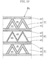
- the conventional dehumidification unit Z 0 is formed by sequentially laminating an adsorption element 31 having a large number of air ventilation passages 35, 35, ... each supporting on its interior surface an adsorbent, and a cooling element 41 having a large number of air ventilation passages 45, 45, .... in a 90-degree plane phase so that the air ventilation passages 35 are approximately orthogonal to the air ventilation passages 45.
- humid air i.e., air to be processed
- cooling air flows through the air ventilation passages 45, 45, ... of each cooling element 41.
- the moisture contained in the humid air is adsorption-removed by the adsorbent supported on the wall surface of the air ventilation passage 35, and the humid air is changed into a stream of low-humidity air.
- the conventional dehumidification unit Z 0 is made up of the adsorption elements 31 and the cooling elements 41, and each adsorption element 31 is composed of an air ventilation passage forming member 32 bent in the shape of a corrugated plate, and a pair of tabular side-plate members 33, 33 respectively firmly attached to both sides of the air ventilation passage forming member 32.
- Both the air ventilation passage forming member 32 and the side-plate members 33, 33 are formed of fiber paper made of ceramic fibers, and an adsorbent, such as silica gel etcetera, is supported on their surface.
- each cooling element 41 is made up of an air ventilation passage forming member 42 bent in the shape of a corrugated plate, and a pair of tabular side-plate members 43, 43 respectively firmly attached to both sides of the air ventilation passage forming member 42.
- Both the air ventilation passage forming member 42 and the side-plate members 43, 43 are formed by a sheet metal (thin metallic plate) made of aluminum etcetera.
- the air ventilation passage 35 on the side of the adsorption element 31 and the air ventilation passage 45 on the side of the cooling element 41 are adjacently formed, with a two-ply wall part (formed by attachment of one of the side-plate members 33, 33 of the adsorption element 31 to one of the side-plate members 43, 43 of the cooling element 41) lying between the air ventilation passage 35 and the air ventilation passage 45 (see Figure 20 ).
- heat exchange between the humid air on the side of the air ventilation passage 35 of the adsorption element 31 and the cooling air on the side of the air ventilation passage 45 of the cooling element 41 i.e., heat transfer from the adsorption element 31 towards the cooling element 41, is always conducted through the aforesaid two-ply wall part made up of the side-plate members 33, 43.
- an object of the present invention is to provide a dehumidification unit capable of maintaining its dehumidification capability at high levels over a long period of time by accomplishing improvement in the performance of heat transfer between the adsorption element and the cooling element, and to provide an adsorption element suitable for use in such a dehumidification unit.
- the present invention employs the following configurations as specific means capable of providing solutions to the above-described problems.
- a first invention of the present application provides a dehumidification unit comprising alternate laminations of an adsorption element 1 which supports an adsorbent and which is provided with a first air ventilation passage 3 through which air (Aa) to be processed is passed, and a cooling element 2 which is provided with a second air ventilation passage 4 through which cooling air (Ab) is passed, and the dehumidification unit of the first invention is characterized in that the first air ventilation passage 3 of the adsorption element 1 and the second air ventilation passage 4 of the cooling element 2 are adjacently formed, with a single plate member P lying between the first air ventilation passage 3 and the second air ventilation passage 4.
- a dehumidification unit according to the first invention, which is characterized in that the plate member P is a side-plate member 12 which is made of fiber paper and which constitutes a side wall of the adsorption element 1 relative to the lamination direction thereof, and that the side-plate member 12 directly faces the second air ventilation passage 4 of the cooling element 2 and, in addition, a separation sheet layer 14 configured to prevent the passage of gas and liquid is formed on a surface of the side-plate member 12 on the side of the second air ventilation passage 4.
- a dehumidification unit according to the first invention, which is characterized in that the plate member P is a side-plate member 22 which is formed by a metallic or resinous member and which constitutes a side wall of the cooling element 2 relative to the lamination direction thereof, and that the side-plate member 22 directly faces the first air ventilation passage 3 of the adsorption element 1.
- a dehumidification unit according to the first invention, which is characterized in that the plate member P is a side-plate member 16 which is formed by a metallic or resinous member and which constitutes a side wall of the adsorption element 1 relative to the lamination direction thereof, and that an absorbent is supported on a surface of the side-plate member 16 which faces the first air ventilation passage 3.
- a dehumidification unit according to any one of the first to fourth inventions, which is characterized in that an air ventilation passage forming member 21 of the cooling element 2 is formed by a bending plate member shaped like a corrugated plate.
- a dehumidification unit according to any one of the first to fourth inventions, which is characterized in that an air ventilation passage forming member 21 of the cooling element 2 is formed by a bending plate member shaped like a trapezoidally corrugated plate.
- a dehumidification unit according to any one of the first to fourth inventions, which is characterized in that an air ventilation passage forming member 21 of the cooling element 2 is made up of a plurality of partition walls 23 vertically arranged in the thickness direction of the cooling element 2.
- a dehumidification unit according to the second invention, which is characterized in that the separation sheet layer 14 is formed by attachment of a plastic film, by vapor deposition of a metallic material, or by application of an organic binder.
- a ninth invention of the present application provides an adsorption element in which a large number of air ventilation passages 3, 3, ... are formed on the inside of a single pair of tabular side-plate members 12, 12 spacedely opposed to each other and an absorbent is supported on the side of an interior surface of each of the air ventilation passages 3, 3, ..., and the adsorption element of the ninth invention is characterized in that the side-plate members 12, 12 are each formed of an air and moisture permeable material, and that either or both of exterior surfaces 12a, 12a of the side-plate members 12, 12 are provided with waterproofing means 14.
- a tenth invention of the present application provides an adsorption element in which a large number of air ventilation passages 3, 3, ... are formed at an interior surface 12b of a tabular side-plate member 12 and an absorbent is supported on the side of an interior surface of each of the air ventilation passages 3, 3, ..., and the adsorption element of the tenth invention is characterized in that the side-plate member 12 is composed of an air and moisture permeable material, and that an exterior surface 12a of the side-plate member 12 is provided with waterproofing means 14.
- a dehumidification unit according to the ninth invention or to the tenth invention, which is characterized in that as the permeable material of which the side-plate member 12 is formed, ceramic fiber paper, glass fiber paper, flame resistant paper, or nonwoven fabric is used.
- a dehumidification unit according to the ninth invention or to the tenth invention, which is characterized in that the waterproofing means 14 is formed by attachment of a plastic film to the exterior surface 12a of the side-plate member 12, by application of an organic binder to the exterior surface 12a, or by vapor deposition of a metallic material on the exterior surface 12a.
- a dehumidification unit according to the ninth invention or to the tenth invention, which is characterized in that the waterproofing means 14 is partially provided only in a corresponding area of the exterior surface 12a of the side-plate member 12 to a non waterproofing structure portion of the cooling element 2 which faces the exterior surface 12a.
- the present invention provides the following effects.
- dehumidification units and adsorption elements suitable for use in such dehumidification units according to the present invention will be described more specifically based on their respective embodiments.
- a dehumidification unit Z 1 formed in accordance with a first embodiment of the present invention.
- the dehumidification unit Z 1 is the result of the application of inventions as set forth in claim 1, claim 2, claim 5, and claim 8.
- the dehumidification unit Z 1 is formed in the following way.
- a plurality of adsorption elements 1, 1, ... and a plurality of cooling elements 2, 2, ... are laminated sequentially alternately in a 90-degree plane phase.
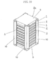
- end plates 9, 9, as shown in Figure 3.
- Two end plates 9, 9 are connected together by four frame members 10, 10, ... which are arranged along the four corners of the laminated body, whereby these components are combined into a single piece.
- specific constructions for the adsorption element 1 and the cooling element 2 will be described.
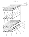
- the adsorption element 1 is shaped like a double-sided cardboard made up of a below-mentioned air ventilation passage forming member 11 and a pair of side-plate members 12, 12.
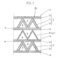
- the cooling element 2 is deviated 90 degrees in plane phase as if the cooling element 2 and the adsorption element 1 are in the same plane phase, as shown in Figure 2 (the same is applied to Figures 5, 7, 9, 12, and 14 ).
- the air ventilation passage forming member 11 is formed of fiber paper made of ceramic fibers. More specifically, the air ventilation passage forming member 11 is a bending plate member formed by alternately bending a sheet of fiber paper in the thickness direction thereof.
- the air ventilation passage forming member 11 is shaped, as a whole, like a corrugated plate.
- each of the pair of the side-plate members 12, 12 is formed of fiber paper made of ceramic fibers, and is shaped into a flat plate.
- the side-plate members 12, 12 are firmly jointed to both surfaces of the air ventilation passage forming member 11, whereby the side-plate members 12, 12 and the air ventilation passage forming member 11 are combined into a single piece. And, as a result of such a combination, a large number of first air ventilation passages 3, 3, ... extending in parallel with each other are formed by "valley" parts of the air ventilation passage forming member 11.
- a proper adsorbent such as silica gel etcetera
- a separation sheet layer 14 is formed on an exterior surface of one of the pair of the side-plate members 12, 12.
- the separation sheet layer 14 is disposed to prevent the passage of gas and liquid through the side-plate member 12, and to completely separate the first air ventilation passages 3 from second air ventilation passages 4 (described later) on the side of the cooling element 2.
- the separation sheet layer 14 is formed by attaching a plastic film to the surface of the side-plate member 12, by vapor-depositing a metallic material (for example, aluminum) on the surface of the side-plate member 12, or by applying an organic binder, such as aqueous urethane resin etcetera, onto the surface of the side-plate member 12.
- the cooling element 2 is shaped like a single-sided cardboard made up of an air ventilation passage forming member 21 (described later) and a side-plate member 22 (see Figures 1 and 2 ).
- the air ventilation passage forming member 21 is made up of a bending plate member formed by alternately bending a sheet metal of aluminum etcetera or a sheet resin in the thickness direction thereof, and is shaped like, as a whole, a corrugated plate.
- the side-plate member 22 is made up of a sheet metal of aluminum etcetera or a sheet resin, and is shaped like a flat plate.
- the side-plate member 22 is firmly jointed to one surface of the air ventilation passage forming member 21, whereby the side-plate member 22 and the air ventilation passage forming member 21 are combined into a single piece. In this way, the above-described cooling element 2 is obtained. And, as a result of such a combination, a large number of second air ventilation passages 4, 4, ... extending in parallel with each other are formed by "valley" parts of the air ventilation passage forming member 21.
- the adsorption element 1 and the cooling element 2, which are constructed as mentioned above, are arranged such that the side-plate member 12 of the adsorption element 1 provided with the separation sheet layer 14 is positioned face to face with "mountain" parts of the air ventilation passage forming member 21 of the cooling element 2, and are laminated sequentially alternately in a 90-degree plane phase relative to each other.
- These elements as a laminated body are firmly joined together by the end plates 9, 9 and the frame members 10, 10, ..., thereby to provide the dehumidification unit Z 1 having a rectangular block-like outer appearance (see Figure 3 ).
- this dehumidification unit Z 1 humid air as the to-be-processed air (Aa) is passed through the first air ventilation passages 3, 3, ... of each adsorption element 1 and, on the other hand, the cooling air (Ab) is passed through the second air ventilation passages 4, 4, ... of each cooling element 2.
- the moisture contained in the to-be-processed air (Aa) is adsorption-removed by the adsorbent supported on the adsorption element 1, and heat of adsorption resulting from such moisture adsorption exchanges heat with the cooling air (Ab) and is liberated towards the cooling air (Ab).
- the adsorption capability of the adsorbent is maintained at satisfactory levels over a long period of time, and the dehumidification unit Z 1 demonstrates high dehumidification performance.
- the inventions as set forth in claim 1, claim 2, claim 5, and claim 8 of the present application are applied to the construction of the adsorption element 1 and to the construction of the cooling element 2, thereby securing dehumidification performance of higher level.
- the first air ventilation passages 3, 3, ... of the adsorption element 1 and the second air ventilation passages 4, 4, ... of the cooling element 2 are adjacently formed, with only the one side-plate member 12 lying therebetween and, in addition, the first air ventilation passages 3, 3, ... are completely separated from the second air ventilation passages 4, 4, ... by the separation sheet layer 14. Accordingly, on the side of the one side-plate member 12, only the one side-plate member 12 exists as resistance against heat transfer between the first air ventilation passages 3 on the side of the adsorption element 1 and the second air ventilation passages 4 on the side of the cooling element 2.
- the other side-plate member 12 of the adsorption element 1 is attached to the side-plate member 22 of the cooling element 2. Therefore, on the side of the other side-plate member 12, two plate members, i.e., the other side-plate member 12 and the side-plate member 22 of the cooling element 2, exist as resistance against heat transfer.
- the side of the one side-plate member 12 of the adsorption element 1 is compared with the side of the other side-plate member 12 of the adsorption element 1. On the side of the one side-plate member 12, there is less heat transfer resistance than on the side of the other side-plate member 12, and the efficiency of liberation of the heat of adsorption increases correspondingly and dehumidification performance is also maintained at satisfactory levels.
- the dehumidification unit Z 1 of the present embodiment has, as a whole, higher heat transfer performance and, as a result, the dehumidification performance of the dehumidification unit Z 1 will be maintained at satisfactory levels over a long period of time.
- the dehumidification unit Z 1 of the present embodiment it is arranged such that, on the side of the one side-plate member 12 of the adsorption element 1, only the one side-plate member 12 is interposed between the first and second air ventilation passages 3, 4 which are adjacently formed in the lamination direction.
- the dimension of the dehumidification unit Z 1 relative to the height direction thereof is reduced by an amount corresponding to reduction in the number of plate members to be interposed between the first and second air ventilation passages 3, 4.
- costs are cut because the number of component members is reduced.
- one of the pair of the side-plate members 12, 12 of the adsorption element 1 that is provided with the separation sheet layer 14 corresponds to the "plate member P" in the claims.
- dehumidification unit Z 2 formed in accordance with a second embodiment of the present invention.
- the dehumidification unit Z 2 is the result of the application of inventions as set forth in claim 1, claim 2, claim 3, claim 5, and claim 8.
- the dehumidification unit Z 2 is formed by sequentially alternately laminating a plurality of adsorption elements 1, 1, ... and a plurality of cooling elements 2, 2, ... one upon the other in a 90-degree plane phase.
- the dehumidification unit Z 2 of the present embodiment is identical in basic construction with the dehumidification unit Z 1 of the first embodiment, with the exception that the adsorption element 1 of the dehumidification unit Z 2 differs in construction from the adsorption element 1 of the dehumidification unit Z 1 .
- the side-plate member 12 is provided on both sides of the air ventilation passage forming member 11.
- the side-plate member 12 is provided on only one side of the air ventilation passage forming member 11 and the separation sheet layer 14 is provided on an exterior surface of the side-plate member 12.
- the adsorption element 1 of the dehumidification unit Z 2 according to the present embodiment has a construction as a result of removing the other side-plate member 12 from the adsorption element 1 of the dehumidification unit Z 1 according to the first embodiment.
- the air ventilation passages 3, 3, ... of each adsorption element 1 and the second air ventilation passages 4, 4, ... of each cooling element 2 are adjacently formed with only the side-plate member 12 of the adsorption element 1 lying therebetween on the side of one surface of the cooling element 2, while on the other hand they are adjacently formed with only the side-plate member 22 of the cooling element 2 lying therebetween on the side of the other surface (see Figure 5 ).
- the performance of heat transfer between the first air ventilation passage 3 and the second air ventilation passage 4 is improved in all the contact areas between the adsorption element 1 and the cooling element 2 , as a result of which the dehumidification unit Z 2 is improved further in dehumidification capability.
- the side-plate member 12 is provided only on one side of the adsorption element 1. Therefore, when compared to, for example, the foregoing construction in which the side-plate member 12 is provided on each side of the adsorption element 1 of the dehumidification unit Z 1 of the first embodiment, the dehumidification unit Z 2 is made further compact in size relative to its height direction by an amount corresponding to reduction in the number of the side-plate members 12.
- the side-plate member 12 of the adsorption element 1 and the side-plate member 22 of the cooling element 2 each correspond to the "plate member P" as set forth in the claims.
- dehumidification unit Z 3 formed in accordance with a third embodiment of the present invention.
- the dehumidification unit Z 3 is the result of the application of inventions as set forth in claim 1, claim 2, claim 5, and claim 8.
- the dehumidification unit Z 3 is formed by sequentially alternately laminating a plurality of adsorption elements 1, 1, ... and a plurality of cooling elements 2, 2, ... one upon the other in a 90-degree plane phase.
- the dehumidification unit Z 3 of the present embodiment is identical in basic construction with the dehumidification unit Z 1 of the first embodiment, with the exception that they differ from each other in construction of the adsorption element 1 as well as in construction of the cooling element 2.
- each side of the air ventilation passage forming member 11 is provided with the side-plate member 12 and the separation sheet layer 14 is formed only on the surface of one of the pair of the side-plate members 12.
- each of the pair of the side-plate members 12 respectively mounted on both sides of the adsorption element 1 has, on its surface, the separation sheet layer 14.
- the cooling element 2 of the first embodiment is made up of the air ventilation passage forming member 21 and the side-plate member 22.
- the cooling element 2 of the present invention is made up only of the air ventilation passage forming member 21.
- the air ventilation passages 3, 3, ... of each adsorption element 1 and the second air ventilation passages 4, 4, ... of each cooling element 2 are adjacently formed with only the side-plate member 12 of the adsorption element 1 lying therebetween in all the contact areas between the adsorption element 1 and the cooling element 2.
- the performance of heat transfer between the first air ventilation passage 3 and the second air ventilation passage 4 is improved further in comparison with the first embodiment, and the dehumidification unit Z 3 is improved further in dehumidification capability.
- the cooling element 2 is made up only of the air ventilation passage forming member 21 . Therefore, when compared with the case where the cooling element 2 is made up of two different members, e.g., the air ventilation passage forming member 21 and the side-plate member 22 (see the cooling element 2 of the first embodiment), the dehumidification unit Z 3 is formed by a less number of component members, and cost savings are promoted by an amount corresponding to reduction in the number of component members.
- each of the pair of the side-plate members 12, 12 of the adsorption element 1 corresponds to the "plate member P" as set forth in the claims.
- dehumidification unit Z 4 formed in accordance with a fourth embodiment of the present invention.
- the dehumidification unit Z 4 is the result of the application of inventions as set forth in claim 1, claim 2, claim 6, and claim 8.
- the dehumidification unit Z 4 is formed by sequentially alternately laminating a plurality of adsorption elements 1, 1, ... and a plurality of cooling elements 2, 2, ... one upon the other in a 90-degree plane phase.
- the dehumidification unit Z 4 of the present embodiment is identical in basic construction with the dehumidification unit Z 3 of the third embodiment, with the exception that they differ from each other in the cooling element's 2 construction.
- the cooling element 2 of the dehumidification unit Z 3 according to the third embodiment is made up only of the air ventilation passage forming member 21 in the form of a corrugated bending plate member.
- the cooling element 2 of the dehumidification unit Z 4 according to the present embodiment is made up only of a trapezoidally corrugated bending plate member. Accordingly, the dehumidification unit Z 4 differs from the dehumidification unit Z 3 in bending form of the air ventilation passage forming member 21 and in cross-sectional shape of the second air ventilation passage 4 formed by the air ventilation passage forming member 21.
- first air ventilation passages 3 of the adsorption element 1 corresponding to the bottom of the air ventilation passage forming member 21 and their associated second air ventilation passages 4 on the side of the cooling element 2 are adjacently formed with two different plate members (i.e., the bottom of the air ventilation passage forming member 21 and the side-plate member 12 of the adsorption element 1) lying therebetween and, on the other hand, the remaining first air ventilation passages 3 corresponding to the opening of the air ventilation passage forming member 21 and their associated second air ventilation passages 4 are adjacently formed with only a single plate member (i.e., the side-plate member 12 of the adsorption element 1) lying therebetween, as shown in Figure 9. Therefore, the latter one is higher in the performance of heat transfer between the first air ventilation passage 3 and the second air ventilation passage 4 than the former one.
- the total heat transfer performance of the dehumidification unit Z 4 is higher when compared, for example, with the structure of a conventional dehumidification unit (see Figure 17) in which all the first air ventilation passages 3 on the side of the adsorption element 1 and all the second air ventilation passages 4 on the side of the cooling element 2 are adjacently formed, with two sheets of plates lying therebetween.
- the dehumidification unit Z 4 will provide higher-level dehumidification performance.
- the second air ventilation passage 4 of the cooling element 2 has a trapezoidal cross section, because of which the effective sectional area of the second air ventilation passage 4 is large, as compared, for example, with the second air ventilation passage 4 having a triangular cross section as in the cooling element 2 of the dehumidification unit Z 1 according to the first embodiment.
- the rate of flow of the cooling air (Ab) increases correspondingly, and the action of liberation of heat of adsorption is promoted further. As a result, the dehumidification performance of the dehumidification unit Z 4 will be improved to a further extent.
- each of the pair of the side-plate members 12, 12 of the adsorption element 1 corresponds to the "plate member P" as set forth in the claims.
- dehumidification unit Z 5 formed in accordance with a fifth embodiment of the present invention.
- the dehumidification unit Z 5 is the result of the application of inventions as set forth in claim 1, claim 4, and claim 6.
- the dehumidification unit Z 5 is formed by sequentially alternately laminating a plurality of adsorption elements 1, 1, ... and a plurality of cooling elements 2, 2, ... one upon the other in a 90-degree plane phase.
- the dehumidification unit Z 5 of the present embodiment is similar in basic configuration to the dehumidification unit Z 4 of the fourth embodiment, with the exception that they differ from each other in the adsorption element's 1 configuration.
- the adsorption element 1 of the fourth embodiment is made up of the air ventilation passage forming member 11 in the form of a corrugated plate and the pair of the side-plate members 12, 12 all of which are made of fiber paper.
- the adsorption element 1 of the present embodiment is made up of the air ventilation passage forming member 11 in the form of a corrugated plate made of fiber paper and a pair of side-plate members 12, 12 each formed by a sheet metal of aluminum etcetera or by a sheet resin and, in addition, a surface of each of the pair of the side-plate members 12, 12 facing the air ventilation passage forming member 11 supports thereon an absorbent to form an absorbent layer 18.
- the cooling element 2 of the present embodiment is made up of a bending plate shaped like a trapezoidally corrugated bending plate which is formed by a sheet metal of aluminum etcetera or by a sheet resin.
- first air ventilation passages 3 of the adsorption element 1 corresponding to the bottom of the air ventilation passage forming member 21 and their associated second air ventilation passages 4 on the side of the cooling element 2 are adjacently formed, with two different plate members (i.e., the bottom of the air ventilation passage forming member 21 and the side-plate member 12 of the adsorption element 1) lying therebetween and, on the other hand, the remaining first air ventilation passages 3 corresponding to the opening of the air ventilation passage forming member 21 and their associated second air ventilation passages 4 are adjacently formed, with only a single plate member (i.e., the side-plate member 12) lying therebetween, as shown in Figure 12. Therefore, the latter one is higher in the performance of heat transfer between the first air ventilation passage 3 and the second air ventilation passage 4 than the former one.
- the total heat transfer performance of the dehumidification unit Z 5 is higher when compared, for example, with the structure of a conventional dehumidification unit (see Figure 19) in which all the first air ventilation passages 3 on the side of the adsorption element 1 and all the second air ventilation passages 4 on the side of the cooling element 2 are adjacently formed, with two sheets of plates lying therebetween.
- the side-plate member 16 is formed by a sheet metal of aluminum etcetera
- the transfer of heat between the air ventilation passage 3 and the air ventilation passage 4 is promoted further, when compared with the case in which the side-plate member 16 is formed of fiber paper as in the fourth embodiment, because in the former case such a metal material has a higher heat transfer rate.
- the efficiency of liberation of heat of adsorption generated in the absorbent towards the cooling air (Ab) is also improved.
- the dehumidification unit Z 5 will have still higher level dehumidification capability.
- each of the pair of the side-plate members 16, 16 of the adsorption element 1 corresponds to the "plate member P" as set forth in the claims.
- dehumidification unit Z 6 formed in accordance with a sixth embodiment of the present invention.
- the dehumidification unit Z 6 is the result of the application of inventions as set forth in claim 1, claim 4, and claim 7.
- the dehumidification unit Z 6 is formed by sequentially alternately laminating a plurality of adsorption elements 1, 1, ... and a plurality of cooling elements 2, 2, ... one upon the other in a 90-degree plane phase, and by firmly joining together the elements thus laminated by the upper and lower end plates 9, 9 and the four frame members 10, 10 ,....
- the dehumidification unit Z 6 of the present embodiment is similar in basic configuration to the dehumidification unit Z 5 of the fifth embodiment, with the exception that they differ from each other in the cooling element's 2 configuration.
- the cooling element 2 is formed by a bending plate member, more specifically a sheet metal of aluminum etcetera or a sheet resin shaped like a trapezoidally corrugated plate.
- the cooling element 2 of the present embodiment is made up only of the air ventilation passage forming member 21 formed by arranging, in a face to face manner and at given intervals, a plurality of strip-like partition wall member 23, 23, ... each formed of a sheet metal of aluminum etcetera or of a sheet resin.
- the adsorption element 1 of the present embodiment is made up of the air ventilation passage forming member 11 made of fiber paper and the pair of the side-plate members 16, 16 each composed of a sheet metal of aluminum etcetera, or of a sheet resin.
- the dehumidification unit Z 6 provides higher heat transfer performance, when compared, for example, with the structure of the conventional dehumidification unit (see Figure 19) in which all the first air ventilation passages 3 on the side of the adsorption element 1 and all the second air ventilation passages 4 on the side of the cooling element 2 are adjacently formed, with two sheets of plates lying therebetween.
- the side-plate member 16 is formed by a sheet metal of aluminum etcetera
- the transfer of heat between the air ventilation passage 3 and the air ventilation passage 4 is promoted further when compared with the case in which the side-plate member 16 is formed of fiber paper as in the fourth embodiment, because in the former case such a metal material has a higher heat transfer rate.
- the absorbent supported directly on the side-plate member 16 of high heat transfer rate because of the absorbent supported directly on the side-plate member 16 of high heat transfer rate, the efficiency of liberation of heat of adsorption generated in the absorbent towards the cooling air (Ab) is also improved.
- the dehumidification unit Z 6 will have still higher level dehumidification capability.
- the cooling element 2 is made up only of the air ventilation passage forming member 21 made up of the plural partition wall members 23, 23, ... arranged in an opposing manner at predetermined intervals.
- the cooling element 2 is formed using a bending plate member, further weight savings or cost savings are provided.
- each of the pair of the side-plate members 16, 16 of the adsorption element 1 corresponds to the "plate member P" as set forth in the claims.
- an adsorption element 1 formed in accordance with a seventh embodiment of the present invention is constructed as follows.
- the adsorption element 1 is disposed face to face with a cooling element having surfaces neither of which has a waterproofing structure, like the cooling element 2 for use in the dehumidification unit Z 3 of the third embodiment.
- the adsorption element 1 has a structure suitable for constituting a dehumidification unit together with the cooling element.
- the adsorption element 1 is shaped like a double-sided cardboard made up of a below-mentioned air ventilation passage forming member 11 and a pair of side-plate members 12, 12.
- the air ventilation passage forming member 11 is basically made of a permeable material.
- the air ventilation passage forming member 11 is formed of ceramic fiber paper, glass fiber paper, flame resistant paper, or nonwoven fabric.
- the air ventilation passage forming member 11 is bent alternately in its thickness direction so that the air ventilation passage forming member 11 is shaped, as a whole, like a corrugated plate.
- each of the pair of the side-plate members 12, 12 is basically formed of a permeable material.
- each side-plate member 12 is formed of ceramic fiber paper, glass fiber paper, flame resistant paper, or nonwoven fabric and is shaped like a flat plate.
- the air ventilation passage forming member 11 is sandwiched between the pair of the side-plate members 12, 12 from both the sides relative to the plate thickness direction so that they are firmly jointed together and are combined into a single piece. And, in such a combined state of the air ventilation passage forming member 11 and the side-plate members 12, 12, a large number of air ventilation passages 3, 3, ... extending in parallel with each other are formed by "valley" parts of the air ventilation passage forming member 11 and interior surfaces 12b, 12b of the side-plate members 12, 12 situated face to face with the valley parts.
- a proper adsorbent such as silica gel etcetera, is supported on the air ventilation passage forming member 11 and side-plate members 12, 12 combined together by means of a dipping technique or the like, thereby to provide them with a required adsorption capability.
- separation sheet layers 14, 14 are formed on exterior surfaces 12a, 12a of the side-plate members 12, 12, respectively.
- the separation sheet layer 14 is provided so that, when the dehumidification unit is formed by arranging the cooling element 2 on each side of the adsorption element 1 in a face-to-face manner, it is possible to secure the seal properties between the adsorption element 1 and each cooling element 2.
- the separation sheet layer 14 is formed by attachment of a plastic film to the exterior surface 12a of the side-plate member 12, by application of an organic binder, such as aqueous urethane resin etcetera, to the exterior surface 12a, or by vapor deposition of a metallic material of high heat transfer rate (for example, aluminum, copper etcetera) on the exterior surface 12a.
- an organic binder such as aqueous urethane resin etcetera
- a metallic material of high heat transfer rate for example, aluminum, copper etcetera
- the adsorption element 1 of the present embodiment is obtained as follows. An adsorbent is supported on the air ventilation passage forming member 11 and side-plate members 12, 12 which are combined into a single piece shaped like a double-sided cardboard and the separation sheet layers 14, 14 are formed on the exterior surfaces 12a, 12a of the side-plate members 12, 12, respectively. As a result of such arrangement, the following specific operation/working effects are attained.
- both the air ventilation passage forming member 11 and the side-plate members 12, 12 are made of a permeable material such as ceramic fiber paper, glass fiber paper, flame resistant paper, or nonwoven fabric, and support thereon an adsorbent, as a result of which the inner surface of each of the air ventilation passages 3, 3 is formed as an adsorbent layer permeable to air. Accordingly, when the air (Aa) to be processed flows through the inside of the air ventilation passages 3, 3, ..., the to-be-processed air (Aa) easily enters the interior of the adsorbent layer, and the action of adsorption and removal of the moisture contained in the air (Aa) is performed efficiently. As a result, the adsorption element 1 will demonstrate high adsorption performance.
- the air ventilation passage forming member 11 and the side-plate members 12, 12 are each formed of ceramic fiber paper, glass fiber paper, flame resistant paper, or nonwoven fabric, weight and cost savings thereof are, of course, provided when compared to the case where these members are formed from plates of resin or metal and, in addition, especially when ceramic fiber paper or glass fiber paper is used, the use reliability is upgraded by their flame retardancy. Moreover, when using flame resistant paper or nonwoven fabric, there is also an advantage that further cost savings can be attained.
- the separation sheet layer 14 is formed on each of the exterior surfaces 12a, 12a of the side-plate members 12, 12.
- the cooling elements 2, 2 opposite to the exterior surfaces 12a, 12a do not have a waterproofing structure (for example, as in the structure of the cooling element 2 shown in Figure 7 )
- the seal properties between the adsorption element 1 and the cooling element 2 are secured by the separation sheet layer 14.
- the adsorption element 1 will demonstrate high adsorption performance.
- the separation sheet layers 14, 14 are provided respectively on the exterior surfaces 12a, 12a of the side-plate members 12, 12 of the adsorption element 1, whereby the seal properties between the adsorption element 1 and the cooling element 2 which faces the adsorption element 1 are secured. This means that there is no need to provide a waterproofing structure on the side of the cooling element 2 facing the exterior surface 12a provided with the separation sheet layer 14.
- a part or a large part of its side surface member is removed so as to bring the cooling air (Ab) flowing on the side of the cooling element 2 into direct contact with the side-plate member 12 of the adsorption element 1, whereby the efficiency of heat transfer therebetween is still further improved, and further improvement in adsorption performance of the adsorption element 1 can be expected correspondingly.
- an adsorption element 1 formed in accordance with an eighth embodiment of the present invention is disposed face to face with a cooling element having surfaces only one of which is provided with a waterproofing structure, such as the cooling element 2 for use in the dehumidification unit Z 1 of the first embodiment (see Figure 2 ).
- the adsorption element 1 has a structure suitable for constituting a dehumidification unit together with such a cooling element.
- the adsorption element 1 is shaped like a double-sided cardboard made up of an air ventilation passage forming member 11 and a pair of side-plate members 12, 12 .
- the adsorption element 1 of the present embodiment has the same basic construction as the adsorption element 1 of the seventh embodiment, but they differ from each other in the following.
- the adsorption element 1 of the seventh embodiment it is arranged such that each of the exterior surfaces 12a, 12a of the side-plate members 12, 12 is provided with a respective separation sheet layer 14.
- the separation sheet layer 14 is provided on only one of the exterior surfaces 12a, 12a of the side-plate members 12, 12 and the other exterior surface 12a remains exposed.
- the side-plate member 12 on which the separation sheet layer 14 is formed is made to face a surface of the cooling element 2 on which no waterproofing structure is provided (for example, a surface of the cooling element 2 of Figure 2 on which the side-plate member 22 is not mounted and at which the air ventilation passage forming member 21 is directly exposed), and the side-plate member 12 on which the separation sheet layer 14 is not formed is made to face a surface of the cooling element 2 provided with a waterproofing structure (for example, a surface of the cooling element 2 of Figure 2 situated on the side of the side-plate member 22) and, as a result of such arrangement, the seal properties between the adsorption element 1 and the cooling element 2 are secured by the separation sheet layer 14 on one side of the adsorption element 1 and by the side-plate member 22 of the cooling element 2 on the other side. Accordingly, the same operation/working effects as accomplished by the adsorption element 1 of the seventh embodiment are attained.
- an adsorption element 1 formed in accordance with a ninth embodiment of the present invention is disposed face to face with a cooling element having surfaces only one of which is provided with a waterproofing structure, such as the cooling element 2 for use in the dehumidification unit Z 2 of the second embodiment (see Figure 5 ).
- the adsorption element 1 has a structure suitable for constituting a dehumidification unit together with such a cooling element.
- the adsorption element 1 of the present invention is able to secure higher heat transfer efficiency when compared to the adsorption element 1 of the eighth embodiment.
- the adsorption element 1 of the present embodiment is shaped like a single-sided cardboard made up of an air ventilation passage forming member 11 and a single side-plate member 12, wherein the separation sheet layer 14 is provided on the exterior surface 12a of the side-plate member 12.
- the side-plate member 12 on which the separation sheet layer 14 is formed is made to face a surface of the cooling element 2 on which no waterproofing structure is provided (for example, a surface of the cooling element 2 of Figure 5 on which the side-plate member 22 is not mounted and at which the air ventilation passage forming member 21 is directly exposed), and the side-plate member 12 on which the separation sheet layer 14 is not formed is made to face a surface of the cooling element 2 provided with a waterproofing structure (for example, a surface of the cooling element 2 of Figure 5 situated on the side of the side-plate member 22) and, as a result of such arrangement, the seal properties between the adsorption element 1 and the cooling element 2 are secured by the separation sheet layer 14 on one side of the adsorption element 1 and by the side-plate member 22 of the cooling element 2 on the other side.
- a waterproofing structure for example, a surface of the cooling element 2 of Figure 5 situated on the side of the side-plate member 22
- the same operation/working effects as accomplished by the adsorption element 1 of the seventh embodiment are attained.
- the air (Aa) to be processed flowing in the inside of the air ventilation passages 3 is brought into direct contact with the cooling element 2, thereby securing heat transfer efficiency at still higher levels in comparison with the case where the air (Aa) is brought into contact with the cooling element 2 through the side-plate member 12 as in the adsorption element 1 of the eighth embodiment.
- the present invention is usefully applicable to dehumidification units and to adsorption elements for use in such dehumidification units.
Landscapes
- Engineering & Computer Science (AREA)
- Chemical & Material Sciences (AREA)
- General Engineering & Computer Science (AREA)
- Mechanical Engineering (AREA)
- Physics & Mathematics (AREA)
- Thermal Sciences (AREA)
- Chemical Kinetics & Catalysis (AREA)
- Oil, Petroleum & Natural Gas (AREA)
- General Chemical & Material Sciences (AREA)
- Analytical Chemistry (AREA)
- Combustion & Propulsion (AREA)
- Dispersion Chemistry (AREA)
- Drying Of Gases (AREA)
- Solid-Sorbent Or Filter-Aiding Compositions (AREA)
Applications Claiming Priority (1)
| Application Number | Priority Date | Filing Date | Title |
|---|---|---|---|
| PCT/JP2002/007377 WO2004010055A1 (fr) | 2002-07-22 | 2002-07-22 | Element de deshumidification et element adsorbant destine a cet element de deshumidification |
Publications (3)
| Publication Number | Publication Date |
|---|---|
| EP1553354A1 true EP1553354A1 (fr) | 2005-07-13 |
| EP1553354A4 EP1553354A4 (fr) | 2010-01-20 |
| EP1553354B1 EP1553354B1 (fr) | 2011-03-16 |
Family
ID=30490765
Family Applications (1)
| Application Number | Title | Priority Date | Filing Date |
|---|---|---|---|
| EP02749329A Expired - Lifetime EP1553354B1 (fr) | 2002-07-22 | 2002-07-22 | Element de deshumidification et element adsorbant destine a cet element de deshumidification |
Country Status (6)
| Country | Link |
|---|---|
| US (1) | US7470311B2 (fr) |
| EP (1) | EP1553354B1 (fr) |
| CN (1) | CN100402936C (fr) |
| AT (1) | ATE502263T1 (fr) |
| DE (1) | DE60239494D1 (fr) |
| WO (1) | WO2004010055A1 (fr) |
Cited By (3)
| Publication number | Priority date | Publication date | Assignee | Title |
|---|---|---|---|---|
| EP1553355A4 (fr) * | 2002-07-24 | 2010-01-20 | Daikin Ind Ltd | Element de deshumidification |
| WO2010132983A1 (fr) | 2009-05-18 | 2010-11-25 | Dpoint Technologies Inc. | Membranes revêtues pour l'échange enthalpique et d'autres applications |
| EP2026029A4 (fr) * | 2006-06-05 | 2013-11-20 | Rengo Co Ltd | Feuilles pour des échangeurs de chaleur totale |
Families Citing this family (41)
| Publication number | Priority date | Publication date | Assignee | Title |
|---|---|---|---|---|
| KR20080004624A (ko) * | 2005-04-22 | 2008-01-09 | 안그스트롬 파워 인코퍼레이티드 | 복합 수소 저장 재료 및 그와 관련된 방법 |
| US8372184B2 (en) | 2005-04-22 | 2013-02-12 | Societe Bic | Composite hydrogen storage material and methods related thereto |
| US7981199B2 (en) * | 2005-12-19 | 2011-07-19 | Behr Gmbh & Co. Kg | Sorber heat exchanger wall and sorber heat exchanger |
| US7563305B2 (en) | 2006-06-23 | 2009-07-21 | Angstrom Power Incorporated | Fluid enclosure and methods related thereto |
| WO2008041327A1 (fr) * | 2006-10-03 | 2008-04-10 | Mitsubishi Electric Corporation | Élément d'échange thermique total et appareil d'échange thermique total |
| US8372561B2 (en) * | 2007-03-21 | 2013-02-12 | Societe Bic | Composite fluid storage unit with internal fluid distribution feature |
| JP5266657B2 (ja) * | 2007-03-30 | 2013-08-21 | 三菱樹脂株式会社 | 車両用除加湿装置 |
| JP5103993B2 (ja) * | 2007-04-06 | 2012-12-19 | 三菱樹脂株式会社 | 車両用除加湿装置 |
| US8091868B2 (en) * | 2008-07-23 | 2012-01-10 | GM Global Technology Operations LLC | WVT design for reduced mass and improved sealing reliability |
| US20100132548A1 (en) * | 2008-12-17 | 2010-06-03 | Dunne Stephen R | Temperature controlled adsorption for dehydration of water rich streams |
| US8226746B2 (en) * | 2008-12-17 | 2012-07-24 | Uop Llc | Indirectly heated temperature controlled adsorber for sorbate recovery |
| US8227648B2 (en) * | 2008-12-17 | 2012-07-24 | Uop Llc | Combined temperature controlled water adsorption and two stage heat pump process for fuel ethanol dehydration |
| US8067646B2 (en) * | 2008-12-17 | 2011-11-29 | Uop Llc | Combined temperature controlled adsorption and heat pump process for fuel ethanol dehydration |
| CN102378882B (zh) * | 2009-03-31 | 2014-12-03 | 贝洱两合公司 | 工作介质存储器、热交换器和热泵 |
| WO2010129232A1 (fr) | 2009-04-27 | 2010-11-11 | Dri-Eaz Products, Inc. | Systèmes et procédés pour actionner et surveiller des déshumidificateurs |
| WO2011033624A1 (fr) * | 2009-09-16 | 2011-03-24 | 三菱電機株式会社 | Élément d'échange de chaleur à enthalpie totale |
| DE102009053629B4 (de) | 2009-11-17 | 2021-08-26 | Institut für Luft- und Kältetechnik gGmbH | Anordnung zur Kühlung oder Heizung eines Raumes |
| JP4801197B2 (ja) * | 2009-12-11 | 2011-10-26 | 琢昌 渡邊 | 電気自動車用防曇・空調システム |
| US8685153B2 (en) * | 2010-01-26 | 2014-04-01 | Micropore, Inc. | Adsorbent system for removal of gaseous contaminants |
| JP5506441B2 (ja) * | 2010-02-09 | 2014-05-28 | 三菱電機株式会社 | 全熱交換素子および全熱交換器 |
| WO2011120054A2 (fr) * | 2010-03-26 | 2011-09-29 | Joseph Ellsworth | Dessiccatif composite, et système et procédé air/eau |
| WO2011132527A1 (fr) * | 2010-04-22 | 2011-10-27 | 三菱樹脂株式会社 | Élément d'adsorption et dispositif utilisant celui-ci |
| EP2627430A4 (fr) | 2010-10-14 | 2014-10-29 | Micropore Inc | Ensemble cartouche adsorbante doté d'un bouchon terminal |
| CN102538547A (zh) * | 2010-12-28 | 2012-07-04 | 常州碳元科技发展有限公司 | 自调节型高散热膜复合材料及其制造方法 |
| DE112012003607T5 (de) | 2011-08-31 | 2014-05-15 | Dri-Eaz Products, Inc. | Entfeuchter mit einer verbesserten Fluidhandhabung sowie assoziierte Verfahren zur Verwendung und Herstellung |
| AU2012323876B2 (en) * | 2011-10-14 | 2017-07-13 | Legend Brands, Inc. | Dehumidifiers having improved heat exchange blocks and associated methods of use and manufacture |
| EP4245399A1 (fr) | 2012-04-24 | 2023-09-20 | Micropore, Inc. | Matériau adsorbant durable et paquets adsorbants et leur procédé de fabrication |
| CN103732037B (zh) * | 2012-10-12 | 2016-12-21 | 台达电子工业股份有限公司 | 热交换装置及应用其的电子装置 |
| USD731632S1 (en) | 2012-12-04 | 2015-06-09 | Dri-Eaz Products, Inc. | Compact dehumidifier |
| CN104110973A (zh) * | 2014-07-16 | 2014-10-22 | 袁野 | 基于瓦楞和平板的蒸发冷却芯体及其制作方法 |
| NL2013565B1 (en) * | 2014-10-02 | 2016-09-07 | 2Ndair B V | Air-conditioner module and use thereof. |
| WO2016172430A1 (fr) * | 2015-04-22 | 2016-10-27 | Keystone Engineering Company | Réglage du centre de gravité de réservoirs de liquide s'utilisant dans un engin spatial |
| US10840521B2 (en) * | 2015-12-30 | 2020-11-17 | Mann+Hummel Gmbh | Humidifier, for example for a fuel cell |
| WO2018101205A1 (fr) * | 2016-12-01 | 2018-06-07 | 三菱電機株式会社 | Film de déshumidification, élément de déshumidification, procédé de fabrication d'un film de déshumidification et procédé de fabrication d'un élément de déshumidification |
| JPWO2020226048A1 (ja) * | 2019-05-09 | 2021-10-28 | ダイキン工業株式会社 | シート状部材の使用方法 |
| JP6822517B2 (ja) * | 2019-05-09 | 2021-01-27 | ダイキン工業株式会社 | 全熱交換素子 |
| CN110439788B (zh) * | 2019-08-21 | 2024-07-09 | 宁波戴维医疗器械股份有限公司 | 一种医用压缩机 |
| CN115218322B (zh) * | 2021-04-18 | 2024-05-24 | 大金工业株式会社 | 空气处理设备 |
| US20230266074A1 (en) * | 2022-02-20 | 2023-08-24 | Molecule Works Inc. | Device for mass and/or heat transfer and process for capturing a molecule in a process fluid using the device |
| JP7834183B2 (ja) * | 2022-09-09 | 2026-03-23 | 三菱電機株式会社 | 熱交換素子および熱交換換気装置 |
| CN117085459B (zh) * | 2023-10-20 | 2024-02-13 | 中国华能集团清洁能源技术研究院有限公司 | 低温吸附净化装置 |
Family Cites Families (22)
| Publication number | Priority date | Publication date | Assignee | Title |
|---|---|---|---|---|
| SE333631B (fr) * | 1969-07-17 | 1971-03-22 | C Munters | |
| SE431513B (sv) * | 1976-10-20 | 1984-02-13 | Toyo Boseki | Flerskiktsorgan av wellpapp |
| JPS53122361U (fr) | 1977-03-07 | 1978-09-29 | ||
| JPS5530488U (fr) | 1978-08-19 | 1980-02-27 | ||
| JPS5753304Y2 (fr) * | 1978-09-06 | 1982-11-18 | ||
| JPS5539434A (en) | 1978-09-13 | 1980-03-19 | Toshiba Corp | Analog-digital converter |
| FR2441132A1 (fr) * | 1978-11-07 | 1980-06-06 | Mitsubishi Electric Corp | Conditionneur d'air simplifie |
| JPS5617622A (en) | 1979-07-23 | 1981-02-19 | Toshimi Kuma | Deodorizing and dehumidifying element |
| JPS56132471U (fr) * | 1980-03-07 | 1981-10-07 | ||
| JPS56132471A (en) | 1980-03-24 | 1981-10-16 | Naoki Ando | Wind turbine |
| JPS5726331A (en) * | 1980-07-24 | 1982-02-12 | Toyobo Co Ltd | Air cooling system and air conditioning system using activated carbon fiber |
| US5226298A (en) * | 1991-01-16 | 1993-07-13 | Matsushita Electric Industrial Co., Ltd. | Thermoelectric air conditioner with absorbent heat exchanger surfaces |
| JP3233169B2 (ja) * | 1992-05-03 | 2001-11-26 | 株式会社西部技研 | 全熱交換器用素子およびその製造法 |
| JPH08313186A (ja) | 1995-05-24 | 1996-11-29 | Mitsubishi Electric Corp | 熱交換器 |
| US5816315A (en) * | 1995-09-13 | 1998-10-06 | Nautica Dehumidifiers, Inc. | Plate-type crossflow air-to-air heat exchanger having dual pass cooling |
| EP0773412B1 (fr) * | 1995-11-07 | 2003-12-17 | Kabushiki Kaisha Seibu Giken | Dispositif et procédé pour le refroidissement d'un fluide et refroidissement déshydratant du gaz |
| CA2283089C (fr) * | 1999-05-10 | 2004-05-25 | Mitsubishi Denki Kabushiki Kaisha | Echangeur de chaleur et methode pour sa preparation |
| JP3501075B2 (ja) * | 1999-05-10 | 2004-02-23 | 三菱電機株式会社 | 熱交換器及び熱交換器の製造方法 |
| JP2001062242A (ja) * | 1999-08-30 | 2001-03-13 | Seibu Giken Co Ltd | 除湿装置 |
| CN2423555Y (zh) | 1999-12-15 | 2001-03-14 | 于向阳 | 间接蒸发制冷空调机的换热器 |
| US6361588B1 (en) * | 1999-12-22 | 2002-03-26 | Jose Moratalla | Selective permeability energy recovery device |
| AU2002320690B2 (en) * | 2002-07-24 | 2007-03-29 | Daikin Industries, Ltd. | Dehumidifying element |
-
2002
- 2002-07-22 AT AT02749329T patent/ATE502263T1/de not_active IP Right Cessation
- 2002-07-22 US US10/521,561 patent/US7470311B2/en not_active Expired - Fee Related
- 2002-07-22 EP EP02749329A patent/EP1553354B1/fr not_active Expired - Lifetime
- 2002-07-22 CN CNB028293665A patent/CN100402936C/zh not_active Expired - Fee Related
- 2002-07-22 WO PCT/JP2002/007377 patent/WO2004010055A1/fr not_active Ceased
- 2002-07-22 DE DE60239494T patent/DE60239494D1/de not_active Expired - Lifetime
Cited By (5)
| Publication number | Priority date | Publication date | Assignee | Title |
|---|---|---|---|---|
| EP1553355A4 (fr) * | 2002-07-24 | 2010-01-20 | Daikin Ind Ltd | Element de deshumidification |
| EP2026029A4 (fr) * | 2006-06-05 | 2013-11-20 | Rengo Co Ltd | Feuilles pour des échangeurs de chaleur totale |
| WO2010132983A1 (fr) | 2009-05-18 | 2010-11-25 | Dpoint Technologies Inc. | Membranes revêtues pour l'échange enthalpique et d'autres applications |
| EP2435171A4 (fr) * | 2009-05-18 | 2014-07-09 | Dpoint Technologies Inc | Membranes revêtues pour l'échange enthalpique et d'autres applications |
| US9255744B2 (en) | 2009-05-18 | 2016-02-09 | Dpoint Technologies Inc. | Coated membranes for enthalpy exchange and other applications |
Also Published As
| Publication number | Publication date |
|---|---|
| CN1639516A (zh) | 2005-07-13 |
| EP1553354B1 (fr) | 2011-03-16 |
| WO2004010055A1 (fr) | 2004-01-29 |
| DE60239494D1 (de) | 2011-04-28 |
| ATE502263T1 (de) | 2011-04-15 |
| AU2002320799A1 (en) | 2004-02-09 |
| US20060086125A1 (en) | 2006-04-27 |
| US7470311B2 (en) | 2008-12-30 |
| CN100402936C (zh) | 2008-07-16 |
| EP1553354A4 (fr) | 2010-01-20 |
Similar Documents
| Publication | Publication Date | Title |
|---|---|---|
| US7470311B2 (en) | Dehumidification unit and adsorption element for use in such a dehumidification unit | |
| US10317095B2 (en) | Counter-flow energy recovery ventilator (ERV) core | |
| JP2019504287A (ja) | エンタルピー交換器 | |
| CN101266109A (zh) | 全热交换器及其制造方法 | |
| JPH09173734A (ja) | 一方向にのみ可撓性を有する折りたたみ型フィルタパック | |
| CN104584301A (zh) | 尤其用于燃料电池的加湿装置 | |
| EP3770543B1 (fr) | Élément d'échange de chaleur totale et échangeur de chaleur totale | |
| WO2004010056A1 (fr) | Element de deshumidification | |
| JP2008521587A (ja) | フレームのないプレート状のフィルタ体 | |
| JP2020180735A (ja) | 熱交換素子及びそれを用いた熱交換形換気装置 | |
| JP3840571B2 (ja) | 除湿素子 | |
| JPH11248390A (ja) | 熱交換エレメント及びその製造方法 | |
| JP2002310550A (ja) | 冷風機用の吸水蒸発ユニット | |
| JPH08313186A (ja) | 熱交換器 | |
| JP3546574B2 (ja) | 熱交換器 | |
| JPH09280765A (ja) | 熱交換エレメント | |
| JP2005040795A (ja) | 除湿素子及び該除湿素子に用いられる吸着用素子 | |
| JPS602888A (ja) | 熱交換素子 | |
| JP2021113650A (ja) | 熱交換素子及びそれを用いた熱交換形換気装置 | |
| JP2021050833A (ja) | 熱交換素子、及びそれを用いた熱交換形換気装置 | |
| JP4269843B2 (ja) | 冷却吸着素子 | |
| KR200273479Y1 (ko) | 건축용 단열보드 | |
| CN216885587U (zh) | 一种防爆隔音镀膜玻璃 | |
| JP2003144834A (ja) | 冷却吸着素子 | |
| WO2009024953A2 (fr) | Échangeur de chaleur |
Legal Events
| Date | Code | Title | Description |
|---|---|---|---|
| PUAI | Public reference made under article 153(3) epc to a published international application that has entered the european phase |
Free format text: ORIGINAL CODE: 0009012 |
|
| 17P | Request for examination filed |
Effective date: 20050211 |
|
| AK | Designated contracting states |
Kind code of ref document: A1 Designated state(s): AT BE BG CH CY CZ DE DK EE ES FI FR GB GR IE IT LI LU MC NL PT SE SK TR |
|
| AX | Request for extension of the european patent |
Extension state: AL LT LV MK RO SI |
|
| DAX | Request for extension of the european patent (deleted) | ||
| A4 | Supplementary search report drawn up and despatched |
Effective date: 20091217 |
|
| 17Q | First examination report despatched |
Effective date: 20100421 |
|
| GRAP | Despatch of communication of intention to grant a patent |
Free format text: ORIGINAL CODE: EPIDOSNIGR1 |
|
| GRAS | Grant fee paid |
Free format text: ORIGINAL CODE: EPIDOSNIGR3 |
|
| GRAA | (expected) grant |
Free format text: ORIGINAL CODE: 0009210 |
|
| RTI1 | Title (correction) |
Free format text: DEHUMIDIFICATION UNIT, AND ADSORBING ELEMENT USED FOR THE DEHUMIDIFICATION UNIT |
|
| AK | Designated contracting states |
Kind code of ref document: B1 Designated state(s): AT BE BG CH CY CZ DE DK EE ES FI FR GB GR IE IT LI LU MC NL PT SE SK TR |
|
| REG | Reference to a national code |
Ref country code: GB Ref legal event code: FG4D |
|
| REG | Reference to a national code |
Ref country code: CH Ref legal event code: EP |
|
| REG | Reference to a national code |
Ref country code: IE Ref legal event code: FG4D |
|
| REF | Corresponds to: |
Ref document number: 60239494 Country of ref document: DE Date of ref document: 20110428 Kind code of ref document: P |
|
| REG | Reference to a national code |
Ref country code: DE Ref legal event code: R096 Ref document number: 60239494 Country of ref document: DE Effective date: 20110428 |
|
| REG | Reference to a national code |
Ref country code: NL Ref legal event code: VDEP Effective date: 20110316 |
|
| PG25 | Lapsed in a contracting state [announced via postgrant information from national office to epo] |
Ref country code: ES Free format text: LAPSE BECAUSE OF FAILURE TO SUBMIT A TRANSLATION OF THE DESCRIPTION OR TO PAY THE FEE WITHIN THE PRESCRIBED TIME-LIMIT Effective date: 20110627 Ref country code: GR Free format text: LAPSE BECAUSE OF FAILURE TO SUBMIT A TRANSLATION OF THE DESCRIPTION OR TO PAY THE FEE WITHIN THE PRESCRIBED TIME-LIMIT Effective date: 20110617 Ref country code: SE Free format text: LAPSE BECAUSE OF FAILURE TO SUBMIT A TRANSLATION OF THE DESCRIPTION OR TO PAY THE FEE WITHIN THE PRESCRIBED TIME-LIMIT Effective date: 20110316 |
|
| PG25 | Lapsed in a contracting state [announced via postgrant information from national office to epo] |
Ref country code: AT Free format text: LAPSE BECAUSE OF FAILURE TO SUBMIT A TRANSLATION OF THE DESCRIPTION OR TO PAY THE FEE WITHIN THE PRESCRIBED TIME-LIMIT Effective date: 20110316 Ref country code: CY Free format text: LAPSE BECAUSE OF FAILURE TO SUBMIT A TRANSLATION OF THE DESCRIPTION OR TO PAY THE FEE WITHIN THE PRESCRIBED TIME-LIMIT Effective date: 20110316 Ref country code: FI Free format text: LAPSE BECAUSE OF FAILURE TO SUBMIT A TRANSLATION OF THE DESCRIPTION OR TO PAY THE FEE WITHIN THE PRESCRIBED TIME-LIMIT Effective date: 20110316 Ref country code: BG Free format text: LAPSE BECAUSE OF FAILURE TO SUBMIT A TRANSLATION OF THE DESCRIPTION OR TO PAY THE FEE WITHIN THE PRESCRIBED TIME-LIMIT Effective date: 20110616 |
|
| PG25 | Lapsed in a contracting state [announced via postgrant information from national office to epo] |
Ref country code: BE Free format text: LAPSE BECAUSE OF FAILURE TO SUBMIT A TRANSLATION OF THE DESCRIPTION OR TO PAY THE FEE WITHIN THE PRESCRIBED TIME-LIMIT Effective date: 20110316 |
|
| PG25 | Lapsed in a contracting state [announced via postgrant information from national office to epo] |
Ref country code: EE Free format text: LAPSE BECAUSE OF FAILURE TO SUBMIT A TRANSLATION OF THE DESCRIPTION OR TO PAY THE FEE WITHIN THE PRESCRIBED TIME-LIMIT Effective date: 20110316 Ref country code: PT Free format text: LAPSE BECAUSE OF FAILURE TO SUBMIT A TRANSLATION OF THE DESCRIPTION OR TO PAY THE FEE WITHIN THE PRESCRIBED TIME-LIMIT Effective date: 20110718 |
|
| PG25 | Lapsed in a contracting state [announced via postgrant information from national office to epo] |
Ref country code: CZ Free format text: LAPSE BECAUSE OF FAILURE TO SUBMIT A TRANSLATION OF THE DESCRIPTION OR TO PAY THE FEE WITHIN THE PRESCRIBED TIME-LIMIT Effective date: 20110316 Ref country code: SK Free format text: LAPSE BECAUSE OF FAILURE TO SUBMIT A TRANSLATION OF THE DESCRIPTION OR TO PAY THE FEE WITHIN THE PRESCRIBED TIME-LIMIT Effective date: 20110316 |
|
| PG25 | Lapsed in a contracting state [announced via postgrant information from national office to epo] |
Ref country code: NL Free format text: LAPSE BECAUSE OF FAILURE TO SUBMIT A TRANSLATION OF THE DESCRIPTION OR TO PAY THE FEE WITHIN THE PRESCRIBED TIME-LIMIT Effective date: 20110316 |
|
| PLBE | No opposition filed within time limit |
Free format text: ORIGINAL CODE: 0009261 |
|
| STAA | Information on the status of an ep patent application or granted ep patent |
Free format text: STATUS: NO OPPOSITION FILED WITHIN TIME LIMIT |
|
| 26N | No opposition filed |
Effective date: 20111219 |
|
| PG25 | Lapsed in a contracting state [announced via postgrant information from national office to epo] |
Ref country code: MC Free format text: LAPSE BECAUSE OF NON-PAYMENT OF DUE FEES Effective date: 20110731 Ref country code: DK Free format text: LAPSE BECAUSE OF FAILURE TO SUBMIT A TRANSLATION OF THE DESCRIPTION OR TO PAY THE FEE WITHIN THE PRESCRIBED TIME-LIMIT Effective date: 20110316 |
|
| REG | Reference to a national code |
Ref country code: CH Ref legal event code: PL |
|
| REG | Reference to a national code |
Ref country code: DE Ref legal event code: R097 Ref document number: 60239494 Country of ref document: DE Effective date: 20111219 |
|
| REG | Reference to a national code |
Ref country code: IE Ref legal event code: MM4A |
|
| PG25 | Lapsed in a contracting state [announced via postgrant information from national office to epo] |
Ref country code: CH Free format text: LAPSE BECAUSE OF NON-PAYMENT OF DUE FEES Effective date: 20110731 Ref country code: LI Free format text: LAPSE BECAUSE OF NON-PAYMENT OF DUE FEES Effective date: 20110731 |
|
| PG25 | Lapsed in a contracting state [announced via postgrant information from national office to epo] |
Ref country code: IT Free format text: LAPSE BECAUSE OF FAILURE TO SUBMIT A TRANSLATION OF THE DESCRIPTION OR TO PAY THE FEE WITHIN THE PRESCRIBED TIME-LIMIT Effective date: 20110316 |
|
| PG25 | Lapsed in a contracting state [announced via postgrant information from national office to epo] |
Ref country code: IE Free format text: LAPSE BECAUSE OF NON-PAYMENT OF DUE FEES Effective date: 20110722 |
|
| PG25 | Lapsed in a contracting state [announced via postgrant information from national office to epo] |
Ref country code: LU Free format text: LAPSE BECAUSE OF NON-PAYMENT OF DUE FEES Effective date: 20110722 |
|
| PG25 | Lapsed in a contracting state [announced via postgrant information from national office to epo] |
Ref country code: TR Free format text: LAPSE BECAUSE OF FAILURE TO SUBMIT A TRANSLATION OF THE DESCRIPTION OR TO PAY THE FEE WITHIN THE PRESCRIBED TIME-LIMIT Effective date: 20110316 |
|
| PGFP | Annual fee paid to national office [announced via postgrant information from national office to epo] |
Ref country code: DE Payment date: 20140716 Year of fee payment: 13 |
|
| PGFP | Annual fee paid to national office [announced via postgrant information from national office to epo] |
Ref country code: GB Payment date: 20140716 Year of fee payment: 13 Ref country code: FR Payment date: 20140708 Year of fee payment: 13 |
|
| REG | Reference to a national code |
Ref country code: DE Ref legal event code: R119 Ref document number: 60239494 Country of ref document: DE |
|
| GBPC | Gb: european patent ceased through non-payment of renewal fee |
Effective date: 20150722 |
|
| PG25 | Lapsed in a contracting state [announced via postgrant information from national office to epo] |
Ref country code: GB Free format text: LAPSE BECAUSE OF NON-PAYMENT OF DUE FEES Effective date: 20150722 Ref country code: DE Free format text: LAPSE BECAUSE OF NON-PAYMENT OF DUE FEES Effective date: 20160202 |
|
| REG | Reference to a national code |
Ref country code: FR Ref legal event code: ST Effective date: 20160331 |
|
| PG25 | Lapsed in a contracting state [announced via postgrant information from national office to epo] |
Ref country code: FR Free format text: LAPSE BECAUSE OF NON-PAYMENT OF DUE FEES Effective date: 20150731 |