EP1553465B1 - Lastmechanismus - Google Patents
Lastmechanismus Download PDFInfo
- Publication number
- EP1553465B1 EP1553465B1 EP05000513.1A EP05000513A EP1553465B1 EP 1553465 B1 EP1553465 B1 EP 1553465B1 EP 05000513 A EP05000513 A EP 05000513A EP 1553465 B1 EP1553465 B1 EP 1553465B1
- Authority
- EP
- European Patent Office
- Prior art keywords
- load
- spring
- crank
- attachment
- action
- Prior art date
- Legal status (The legal status is an assumption and is not a legal conclusion. Google has not performed a legal analysis and makes no representation as to the accuracy of the status listed.)
- Ceased
Links
- 230000007246 mechanism Effects 0.000 title claims abstract description 68
- 230000009471 action Effects 0.000 claims description 36
- 238000000926 separation method Methods 0.000 claims description 13
- 238000003384 imaging method Methods 0.000 abstract description 21
- 230000008859 change Effects 0.000 abstract description 13
- 238000006073 displacement reaction Methods 0.000 abstract description 4
- 239000007788 liquid Substances 0.000 description 4
- 230000036316 preload Effects 0.000 description 4
- 239000003086 colorant Substances 0.000 description 3
- 238000007639 printing Methods 0.000 description 3
- 230000002146 bilateral effect Effects 0.000 description 2
- 230000006835 compression Effects 0.000 description 2
- 238000007906 compression Methods 0.000 description 2
- 238000005516 engineering process Methods 0.000 description 2
- 238000000034 method Methods 0.000 description 2
- 238000003825 pressing Methods 0.000 description 2
- 230000001154 acute effect Effects 0.000 description 1
- 230000007423 decrease Effects 0.000 description 1
- 230000001419 dependent effect Effects 0.000 description 1
- 230000000694 effects Effects 0.000 description 1
- 238000007641 inkjet printing Methods 0.000 description 1
- 238000004519 manufacturing process Methods 0.000 description 1
- 239000000463 material Substances 0.000 description 1
- 239000000155 melt Substances 0.000 description 1
- 230000008569 process Effects 0.000 description 1
- 230000001105 regulatory effect Effects 0.000 description 1
- 230000004044 response Effects 0.000 description 1
- 239000007787 solid Substances 0.000 description 1
- 125000000391 vinyl group Chemical group [H]C([*])=C([H])[H] 0.000 description 1
- 229920002554 vinyl polymer Polymers 0.000 description 1
Images




Classifications
-
- G—PHYSICS
- G03—PHOTOGRAPHY; CINEMATOGRAPHY; ANALOGOUS TECHNIQUES USING WAVES OTHER THAN OPTICAL WAVES; ELECTROGRAPHY; HOLOGRAPHY
- G03G—ELECTROGRAPHY; ELECTROPHOTOGRAPHY; MAGNETOGRAPHY
- G03G15/00—Apparatus for electrographic processes using a charge pattern
- G03G15/14—Apparatus for electrographic processes using a charge pattern for transferring a pattern to a second base
- G03G15/16—Apparatus for electrographic processes using a charge pattern for transferring a pattern to a second base of a toner pattern, e.g. a powder pattern, e.g. magnetic transfer
- G03G15/1665—Apparatus for electrographic processes using a charge pattern for transferring a pattern to a second base of a toner pattern, e.g. a powder pattern, e.g. magnetic transfer by introducing the second base in the nip formed by the recording member and at least one transfer member, e.g. in combination with bias or heat
- G03G15/167—Apparatus for electrographic processes using a charge pattern for transferring a pattern to a second base of a toner pattern, e.g. a powder pattern, e.g. magnetic transfer by introducing the second base in the nip formed by the recording member and at least one transfer member, e.g. in combination with bias or heat at least one of the recording member or the transfer member being rotatable during the transfer
-
- G—PHYSICS
- G03—PHOTOGRAPHY; CINEMATOGRAPHY; ANALOGOUS TECHNIQUES USING WAVES OTHER THAN OPTICAL WAVES; ELECTROGRAPHY; HOLOGRAPHY
- G03G—ELECTROGRAPHY; ELECTROPHOTOGRAPHY; MAGNETOGRAPHY
- G03G15/00—Apparatus for electrographic processes using a charge pattern
- G03G15/14—Apparatus for electrographic processes using a charge pattern for transferring a pattern to a second base
- G03G15/16—Apparatus for electrographic processes using a charge pattern for transferring a pattern to a second base of a toner pattern, e.g. a powder pattern, e.g. magnetic transfer
-
- G—PHYSICS
- G03—PHOTOGRAPHY; CINEMATOGRAPHY; ANALOGOUS TECHNIQUES USING WAVES OTHER THAN OPTICAL WAVES; ELECTROGRAPHY; HOLOGRAPHY
- G03G—ELECTROGRAPHY; ELECTROPHOTOGRAPHY; MAGNETOGRAPHY
- G03G15/00—Apparatus for electrographic processes using a charge pattern
- G03G15/14—Apparatus for electrographic processes using a charge pattern for transferring a pattern to a second base
- G03G15/16—Apparatus for electrographic processes using a charge pattern for transferring a pattern to a second base of a toner pattern, e.g. a powder pattern, e.g. magnetic transfer
- G03G15/1665—Apparatus for electrographic processes using a charge pattern for transferring a pattern to a second base of a toner pattern, e.g. a powder pattern, e.g. magnetic transfer by introducing the second base in the nip formed by the recording member and at least one transfer member, e.g. in combination with bias or heat
-
- G—PHYSICS
- G03—PHOTOGRAPHY; CINEMATOGRAPHY; ANALOGOUS TECHNIQUES USING WAVES OTHER THAN OPTICAL WAVES; ELECTROGRAPHY; HOLOGRAPHY
- G03G—ELECTROGRAPHY; ELECTROPHOTOGRAPHY; MAGNETOGRAPHY
- G03G15/00—Apparatus for electrographic processes using a charge pattern
- G03G15/20—Apparatus for electrographic processes using a charge pattern for fixing, e.g. by using heat
- G03G15/2092—Apparatus for electrographic processes using a charge pattern for fixing, e.g. by using heat using pressure only
-
- G—PHYSICS
- G03—PHOTOGRAPHY; CINEMATOGRAPHY; ANALOGOUS TECHNIQUES USING WAVES OTHER THAN OPTICAL WAVES; ELECTROGRAPHY; HOLOGRAPHY
- G03G—ELECTROGRAPHY; ELECTROPHOTOGRAPHY; MAGNETOGRAPHY
- G03G15/00—Apparatus for electrographic processes using a charge pattern
- G03G15/22—Apparatus for electrographic processes using a charge pattern involving the combination of more than one step according to groups G03G13/02 - G03G13/20
- G03G15/24—Apparatus for electrographic processes using a charge pattern involving the combination of more than one step according to groups G03G13/02 - G03G13/20 whereby at least two steps are performed simultaneously
-
- G—PHYSICS
- G03—PHOTOGRAPHY; CINEMATOGRAPHY; ANALOGOUS TECHNIQUES USING WAVES OTHER THAN OPTICAL WAVES; ELECTROGRAPHY; HOLOGRAPHY
- G03G—ELECTROGRAPHY; ELECTROPHOTOGRAPHY; MAGNETOGRAPHY
- G03G15/00—Apparatus for electrographic processes using a charge pattern
- G03G15/20—Apparatus for electrographic processes using a charge pattern for fixing, e.g. by using heat
- G03G15/2003—Apparatus for electrographic processes using a charge pattern for fixing, e.g. by using heat using heat
- G03G15/2014—Apparatus for electrographic processes using a charge pattern for fixing, e.g. by using heat using heat using contact heat
- G03G15/2017—Structural details of the fixing unit in general, e.g. cooling means, heat shielding means
- G03G15/2032—Retractable heating or pressure unit
-
- G—PHYSICS
- G03—PHOTOGRAPHY; CINEMATOGRAPHY; ANALOGOUS TECHNIQUES USING WAVES OTHER THAN OPTICAL WAVES; ELECTROGRAPHY; HOLOGRAPHY
- G03G—ELECTROGRAPHY; ELECTROPHOTOGRAPHY; MAGNETOGRAPHY
- G03G2215/00—Apparatus for electrophotographic processes
- G03G2215/00362—Apparatus for electrophotographic processes relating to the copy medium handling
- G03G2215/00367—The feeding path segment where particular handling of the copy medium occurs, segments being adjacent and non-overlapping. Each segment is identified by the most downstream point in the segment, so that for instance the segment labelled "Fixing device" is referring to the path between the "Transfer device" and the "Fixing device"
- G03G2215/00409—Transfer device
-
- G—PHYSICS
- G03—PHOTOGRAPHY; CINEMATOGRAPHY; ANALOGOUS TECHNIQUES USING WAVES OTHER THAN OPTICAL WAVES; ELECTROGRAPHY; HOLOGRAPHY
- G03G—ELECTROGRAPHY; ELECTROPHOTOGRAPHY; MAGNETOGRAPHY
- G03G2215/00—Apparatus for electrophotographic processes
- G03G2215/01—Apparatus for electrophotographic processes for producing multicoloured copies
- G03G2215/019—Structural features of the multicolour image forming apparatus
- G03G2215/0193—Structural features of the multicolour image forming apparatus transfer member separable from recording member
-
- G—PHYSICS
- G03—PHOTOGRAPHY; CINEMATOGRAPHY; ANALOGOUS TECHNIQUES USING WAVES OTHER THAN OPTICAL WAVES; ELECTROGRAPHY; HOLOGRAPHY
- G03G—ELECTROGRAPHY; ELECTROPHOTOGRAPHY; MAGNETOGRAPHY
- G03G2215/00—Apparatus for electrophotographic processes
- G03G2215/16—Transferring device, details
-
- G—PHYSICS
- G03—PHOTOGRAPHY; CINEMATOGRAPHY; ANALOGOUS TECHNIQUES USING WAVES OTHER THAN OPTICAL WAVES; ELECTROGRAPHY; HOLOGRAPHY
- G03G—ELECTROGRAPHY; ELECTROPHOTOGRAPHY; MAGNETOGRAPHY
- G03G2215/00—Apparatus for electrophotographic processes
- G03G2215/16—Transferring device, details
- G03G2215/1676—Simultaneous toner image transfer and fixing
-
- G—PHYSICS
- G03—PHOTOGRAPHY; CINEMATOGRAPHY; ANALOGOUS TECHNIQUES USING WAVES OTHER THAN OPTICAL WAVES; ELECTROGRAPHY; HOLOGRAPHY
- G03G—ELECTROGRAPHY; ELECTROPHOTOGRAPHY; MAGNETOGRAPHY
- G03G2215/00—Apparatus for electrophotographic processes
- G03G2215/16—Transferring device, details
- G03G2215/1676—Simultaneous toner image transfer and fixing
- G03G2215/168—Simultaneous toner image transfer and fixing at the first transfer point
-
- G—PHYSICS
- G03—PHOTOGRAPHY; CINEMATOGRAPHY; ANALOGOUS TECHNIQUES USING WAVES OTHER THAN OPTICAL WAVES; ELECTROGRAPHY; HOLOGRAPHY
- G03G—ELECTROGRAPHY; ELECTROPHOTOGRAPHY; MAGNETOGRAPHY
- G03G2221/00—Processes not provided for by group G03G2215/00, e.g. cleaning or residual charge elimination
- G03G2221/16—Mechanical means for facilitating the maintenance of the apparatus, e.g. modular arrangements and complete machine concepts
- G03G2221/1642—Mechanical means for facilitating the maintenance of the apparatus, e.g. modular arrangements and complete machine concepts for the transfer unit
Definitions
- marking material is applied to the surface of an intermediate imaging element, such as a belt or a drum.
- the print media to which the image is ultimately to be applied (such as paper) is then pressed against the intermediate imaging element to transfer the image from the intermediate imaging element to the print media.
- an image of ink liquid or dry toner is formed on an electrically charged image receptor.
- the print media is pressed against the image receptor to transfer the image to the print media.
- the image is subsequently fused to the print media by applying pressure with a fuser roller.
- ink is deposited to form an image on the surface of an imaging drum.
- a transfix roller presses the print media against the image-bearing drum surface to transfer the ink image from the drum surface to the print media and fuse the ink image to the print media.
- the pressure applied it is desirable for the pressure applied to be constant, regardless of the thickness of the print medium. Therefore, displacement of the pressure applicator due to different thicknesses of print medium should not materially change the magnitude of the pressure applied. Furthermore, it is often desirable that the pressure applied be balanced across the width of the print medium.
- a spring support of the kind as are used for supporting pipes which in use are subjected to movement comprises a frame, a bell-crank lever pivotally mounted on the frame, spring means acting on the lever, and load connecting means acting on the lever.
- Compensating means (comprising a pivotally mounted link) operates to vary the position at which the load connecting means acts on the lever in such a manner as to maintain a constant load moment on the lever despite variations in the load applied thereto.
- One end of the link is pivoted to the frame, the other end is connected to a toothed carrier wheel which carries the load turnbuckle and can roll in a toothed slot in the lever.
- JP5197296 (patent abstract of Japan) describes a color recorder.
- a means for adjusting the press-contact force between the photosensitive drum and the intermediate transfer cylinder and a means for adjusting the press-contact force between the cylinder and the pressing cylinder are provided so that the press-contact force between them can be adjusted independently of each other.; Therefore, in the case of performing the pressure intermediate transfer and the pressure transfer and fixing of the toner images of respective colors Y, M, C and BK which are successively formed on the photosensitive drum, the press-contact force is adjusted so that the optimum press-contact force may be obtained for the flow characteristic of the toner of the respective colors for every case when intermediate transfer, retransfer and fixing are performed. The transfer, the retransfer and fixing of the toner of the respective colors are respectively excellently performed, thereby obtaining the high-quality image without the transfer paint-out.
- a printer 8 ( Figure 1 ) includes a housing or shell that encloses a print mechanism (not shown).
- the present description references a phase change ink jet print mechanism.
- the print mechanism may also encompass a xerographic or other electrostatic print mechanism.
- ink is typically delivered to the printer in a solid form.
- An ink delivery mechanism melts the ink to a liquid form, and delivers the liquid ink to an inkjet printhead.
- the inkjet printhead ejects drops of the liquid ink from a multitude of inkjet nozzles onto an imaging element, typically an oil-coated drum.
- an imaging element typically an oil-coated drum.
- a transfix mechanism causes the image to be transferred from the imaging element to a print medium, such as paper, card stock, transparency, vinyl, etc. In certain implementations, this transfer process is called transfix because the image is simultaneously transferred and bonded (or fixed) to the print medium.
- the present description refers to a transfix mechanism that simultaneously transfers and bonds the image to the print medium.
- the principles, structures, and methods described are applicable to a variety of mechanisms in which a uniform, regulated pressure is to be applied, including different types of transfer and fusing rollers.
- an exemplary image transfer or transfix mechanism 9 includes an imaging drum 10 on which an image 11 has been formed, and a transfer element, such as a transfix roller 20, used to apply pressure to media 12 interposed between the drum 10 and the roller 20.
- Figure 2 is an end view of the transfix mechanism.
- the imaging drum has a width extending substantially parallel to the axis 22 of the transfix roller 20.
- the transfix roller extends across the width of the imaging drum.
- Another transfix mechanism which may be identical to the one shown in Figures 2 , is positioned at the opposite side of the imaging drum.
- the transfix roller 20 is pressed toward the imaging drum 10 by a transfix lever assembly that includes a roller arm 21.
- the proximal end 24 of the roller arm 21 is attached to the load arm 23 at an arm pivot B.
- the transfix roller 20 has an axis 22 fixed to the roller arm 21 at roller pivot C.
- the proximal end 25 of the load arm 23 is connected to a frame 26 of the printer via a frame pivot connection A.
- the second, distal, end 19 of the roller arm 21 includes an engaging mechanism to cause the roller arm to selectively move toward the imaging drum for the transfix operation.
- the engaging mechanism is a transfix cam follower 27 that rotates on cam follower pivot D and is engaged by a transfix cam 28.
- the transfix mechanism is in a disengaged position.
- the load arm 23 rests at fixed stop G on a fixed portion of the printer frame.
- a load mechanism 30 applies a load force F 0 at a load attachment at the distal end F of the load arm 23 to hold the load arm against the fixed stop G.
- a roller bias spring 29 is connected between a load arm bias connection point H on the load arm 23 and a roller arm bias connection point I on the roller arm 21. This roller bias spring holds the roller arm in position with the cam follower 27 against the transfix cam 28, so that the transfix roller 20 is separated from the surface of the imaging drum 10 and the media 12.
- the roller bias spring may be connected between the roller arm bias connection point I and a fixed portion of the printer frame.
- the bias force provided by the roller bias spring 29 may be only a small fraction of the load force F 0 .
- FIG 3 shows the exemplary transfix mechanism in an engaged position, applying a transfix pressure to press the media 12 against the surface of the imaging drum. Such pressure will cause the image 11 to be transferred and fixed to the media 12 as the imaging drum rotates.
- the transfix cam 28 is rotated about pivot E so that the cam 28 engages the cam follower 27 to cause the distal end 19 of the roller arm 21 to move toward the imaging drum. So moving the roller arm initially causes the roller arm to rotate about its proximal end 24 at the pivot B until the transfix roller 20 engages the media 12.
- the roller arm rotates about pivot C, which is the axis 22 of the transfix roller 20.
- the transfix roller 20 deforms under pressure, there may be some additional rotation about arm pivot B.
- the proximal end of the roller arm then presses against the load arm, lifting the load arm against the load force F 0 applied by the load mechanism 30, and rotating the load arm about a load arm pivot A.
- the arrangement of the transfix mechanism leverages the load force F 0 so that the force of the transfix roller 20 against the media on the imaging drum is much larger than the load force on the distal end of the load arm.
- the load force F 0 at the end of the load arm may be approximately 30 pounds.
- the transfix roller can apply approximately 2446N-2669N (550-600 pounds) of force to press the media against the surface of the imaging drum.
- a constant load force F 0 ensures that the transfix pressure against the media 12 is constant.
- Media 12 of different thicknesses will cause the distal end F of the load arm 23 to assume a position within a range of position when the transfix mechanism is engaged.
- the deflection of the load attachment point at the distal end of the load arm 23 thus depends on the thickness of the media 12.
- the load force F 0 applied to the distal end F of the load arm 23 should not change as the amount of deflection changes.
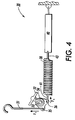
- FIG 4 illustrates an embodiment of the load mechanism 30.
- the load mechanism applies the load force F 0 to the load attachment point on the distal end F of the load arm 23 via a load connector 31.
- One end of the load connector 31 engages the distal end F of the load arm 23 ( Figures 2 and 3 ).
- the end of the load connector 31 has a hook for engaging the load arm to transfer the load force F 0 from the load mechanism 30 to the transfix mechanism 9.
- the load arm 23 pivots about its proximal end A when the transfix mechanism is engaged, the distal end F of the load arm is displaced substantially vertically against the load force F 0 applied by the load mechanism.
- Such displacement moves the load connector 31 in a substantially linear, substantially longitudinal direction.
- the load connector is attached to a crank 32 at connector attachment 35.
- a load spring 38 is also connected to the crank 32 at spring attachment 36.
- a spring hook 41 provides the attachment for the spring.
- the spring 38 applies a spring force F S to the crank at the spring attachment 36.
- the spring is tensioned so that the spring force F S is a tension force.
- the spring force F S creates a moment (torque) in the crank about the crank pivot 33.
- the crank 32 transfers that spring force F S to the load connector 31.
- the geometry of the crank is used to compensate for changes in the spring force due to changes in the spring.
- An embodiment is described in which the spring is an extension spring such that the spring force F S is a tension force that increases as the length of the spring increases.
- the principles described can be applied to embodiments with compression or other types of springs.
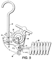
- the crank 32 is arranged so that a relationship exists between the connector attachment 35 and the spring attachment 36 to ensure appropriate transfer of the spring force generated by the spring 38 to the load connector 31.
- one embodiment of the crank 32 is rotatable about a crank pivot 33.
- the crank rotates on a crank bearing 34.
- the connector attachment 35 and the spring attachment 36 are positioned at connector attachment radius R 0 and spring attachment radius R S , respectively, from the crank pivot 33.
- a spring attachment angle ⁇ is between the spring attachment radius R S and a spring effective radius R SE , which is perpendicular to the line of movement of the spring attachment 36 and extending through the crank pivot.
- a connector attachment angle ⁇ is between the connector attachment radius R 0 and a connector effective radius R 0E , which is perpendicular to line of movement of the connector attachment 35 and extends through the crank pivot.
- the spring effective radius R SE (46) and the connector effective radius R 0E (45) are separated by an action separation angle ⁇ .
- the action separation angle ⁇ is 90°, with the spring 38 and the load connector 31 oriented at a right angle.
- other action separation angle ⁇ values can be used.
- an "in-line" crank is configured with an action separation angle of 0° so that the spring and the load connector are oriented in substantially the same direction.
- the load mechanism may include an action separation angle of 180°.
- the crank's connector attachment radius R 0 and spring attachment radius R S are separated from one another by a crank attachment angle ⁇ .
- the arrangement of the connector and spring attachments governs the relationship between the spring force F S and the load force F 0 .
- the connector and spring attachments are arranged on the crank so that as the torque applied to the crank changes over relatively small angles of rotation, the load force F 0 does not change appreciably. This arrangement reduces the effect on the load force F 0 of variations in the spring force as the length of the spring 38 changes.
- the spring force F S is a function of the spring preload force F PL , the amount of longitudinal deflection X of the spring due to rotation of the crank, and the spring rate k.
- the spring preload force is the spring tension exerted by the spring 38 on the crank when the spring attachment angle ⁇ between spring attachment radius and spring effective radius line 46 perpendicular to the spring 38 is 0°.
- the longitudinal deflection of the spring is related to the longitudinal movement of the load connector by the geometry of the crank. The sum of the torque moments on the crank is zero.
- F S R S cos ⁇ F 0 R 0 cos ⁇
- F 0 F S ⁇ R S cos ⁇ R 0 cos ⁇
- crank attachment angle ⁇ is approximately 70°.
- a nominal connector attachment angle ⁇ when the load arm 23 is against the frame stop G ( Figure 2 ) may be 27°.
- a nominal spring attachment angle ⁇ when the load arm 23 is against the frame stop G ( Figure 2 ) m ay be 7 °.
- the spring 38 imparts a spring force of approximately 133 N (30 pounds).
- the transfix mechanism causes the transfix roller 20 to engage the media 12 on the drum 10 ( Figure 3 )
- the distal end F of the load arm 23 is displaced, causing the load connector 31 to move longitudinally (vertically).
- the longitudinal movement of the load connector rotates the crank about its pivot against the tension force of the spring 38.
- the spring attachment angle ⁇ changes from a relatively small angle toward 0°, and then to a relatively small angle on the opposite side of 0°.
- the spring attachment angle is smaller than the load connector attachment angle.
- the geometry of one exemplary embodiment of the transfix mechanism and the load mechanism causes the crank to rotate for maximum media thickness (maximum deflection of the load arm 23) until the connector attachment angle ⁇ is approximately 0°.
- the geometry of the crank is designed so that as the spring force increases, the output force F 0 on the load connectors 31 does not change significantly.
- the crank geometry compensates for the spring rate of the springs so that the output force F 0 is substantially the same regardless of the angle of the crank 32 for small angle changes (generally less than approximately 30°). Variations in media thickness and transfix mechanism manufacture result in different loaded extensions of the load connector 31 and, therefore, different extensions of the springs 38.
- the compensation geometry of the crank 32 ensures that the resulting transfix load will be substantially the same regardless of such variations.
- the torque applied to the crank by the spring 38 is a function of the spring force F S and the effective spring force radius R SE between the pivot 33 and the spring force line of action.
- the balancing torque applied to the crank by the load connector 31 is a function of load force F 0 and the connector effective radius R 0E between the crank pivot 33 and the connector line of action. As the crank rotates, the connector effective radius R 0E changes. Referring, for example, to the configuration shown in Figure 5 , as the load connector 31 moves in response to displacement of the load arm 23 shown in Figures 2 and 3 , the crank rotates clockwise, which in turn extends the spring 38. As the spring 38 lengthens, the spring force F S increases, creating greater torque on the crank.
- the torque applied by the load connector 31 balances the torque due to the spring force F S .
- the connector effective radius R 0E i decreases. Therefore, the magnitude of the load force F 0 needed to create the balancing load torque on the crank need not increase if the geometry of the crank is properly set to provide an connector effective radius that changes at a rate appropriate to the change in the spring force as the crank rotates.
- the spring attachment angle ⁇ remains small as the crank rotates through its normal range of movement, so that the spring effective radius does not vary much.
- the relative lengths of the spring effective radius and the load connector effective radius and/or the relative magnitudes of the action separation angle ⁇ and the crank attachment angle ⁇ determine how to compensate for changes in the spring force due to changes in the spring geometry (length).
- a difference in the magnitude of the action separation angle ⁇ and the crank attachment angle ⁇ are different to provide compensation for a change in the spring force as the spring length changes.
- the crank can be arranged so that the connector effective radius varies in a direction that permits at least some compensation for an increasing spring force as the spring lengthens.
- the end of the spring 38 not attached to the crank may be attached to a fixed anchor, such as a frame portion.
- a tension adjustment mechanism such as a turnbuckle 40, is preferably included to adjust the preload force F PL on the spring 38.
- a second spring hook 43 attaches the spring to the turnbuckle.
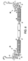
- two load mechanisms 30a, 30b are attached to one another.
- the arrangement illustrated in Figure 6 provides a balanced force to the opposite ends of the transfix roller 20 ( Figure 3 ) without the need to separately adjust each load mechanism.
- the two load connectors 31 of such a bilateral load mechanism are connected to identical cranks and springs.
- a common tension adjuster, such as the turnbuckle 40, attached to both springs 38 of the load mechanisms allows simultaneous and balanced adjustment of the load mechanisms.
- the tension adjuster could be attached on one side of a single spring or a plurality of springs connected in series.
- the complete bilateral load mechanism extends across the width of the transfix roller, and has two load connectors 31. Each load connector applies the load force to a corresponding load arm 23 of substantially identical transfix mechanisms at each end of the transfix roller.
- the ability of the cranks to transfer spring force from vertical to horizontal allows the springs 38 to be installed in a horizontal orientation. Since the two springs 38 point toward each other in the horizontal orientation, they can be fastened to one another via the turnbuckle 40 and spring hooks 43. This configuration eliminates the need for attachment points in the printer case or the printer chassis for the springs. Other embodiments could employ one long spring in place of two short springs, with the turnbuckle 40 on one side of the spring. The horizontal orientation of the springs 38 is advantageous because it places the springs 38 in an area of the printer where there is plenty of room for them. Embodiments have been described in which the spring 38 is an extension spring. Other embodiments may incorporate a compression spring, or other types of springs.
- the load mechanism of embodiments is a self-contained assembly that can be built, tested and calibrated independent of the printer or other device into which it is to be installed. The assembled, tested, and calibrated load mechanism can then be fastened to the printer as a single unit.
- the load connectors 31 may or may not be part of the self-contained assembly.
- An exemplary self-contained load mechanism assembly is shown in Figure 7 .
- the pivots 33 of each crank 32 are fitted into pivot receptacles 41 on a load mechanism frame 42, and secured in place so that the pivot 33 does not move relative to the load mechanism frame.
- the turnbuckle 40 can be adjusted for the proper load force F 0 on the two load connectors 31 with the load mechanism secured to the load mechanism frame.
- the entire load mechanism assembly is attached to the printer chassis inside the printer housing.
- attachment devices such as screws or bolts can be inserted through load mechanism assembly attachment holes 44.
- Such mounting of the load mechanism in the printer does not change the adjustments and calibration of the load force generated by the load mechanism.
- Load assembly mounting tool holes 46 in the load mechanism frame permit mounting tools to position the load connectors on the ends of the load arms 23 after the load assembly has been assembled into the printer.
- the spring 38 rotates the crank 32 counterclockwise until one arm 49 of the T-shaped extension of the crank 32 abuts a hard stop, such as a tab 50 portion of the load mechanism frame.
- the mounting tool holes 46 may be elongated so that a mounting tool 47 having an elongated tip, such as a TORX-head driver bit, can be inserted into the mounting tool hole.
- the hook end of the load connector To attach the load connector 31 onto the distal end F of the load arm, the hook end of the load connector must be raised.
- the mounting tool is inserted into the mounting tool hole 46, where it contacts the crank 32. Within the elongate mounting tool hole, the mounting tool can then rotate the crank 32 clockwise, against the force of the spring 38, to raise the load connectors.
- a TORX-20 driver or similar tool can be used for such rotation of the crank.
- the elongated mounting tool hole may be oriented at an acute angle with respect to the orientation of the load mechanism assembly to improve the contact between the mounting tool and the crank through the range of rotation.
Landscapes
- Physics & Mathematics (AREA)
- General Physics & Mathematics (AREA)
- Ink Jet (AREA)
- Electrostatic Charge, Transfer And Separation In Electrography (AREA)
Claims (7)
- Lastmechanismus zum Anwenden einer Belastungskraft, wobei der Lastmechanismus umfasst:einen Hebel (32) mit einem Hebeldrehzapfen (33);eine Feder (38), die an einer Federbefestigung (36) an dem Hebel befestigt ist; undeinen Lastverbinder (31), der an einer Lastverbinderbefestigung (35) an dem Hebel befestigt ist;wobei die Federbefestigung und die Lastverbinderbefestigung durch einen Hebelbefestigungswinkel (δ) relativ zu dem Hebeldrehzapfen voneinander getrennt sind;wobei die Feder eine Feder-Wirkrichtung relativ zu dem Hebel (32) hat;wobei die Feder-Wirkrichtung einen effektiven Federradius (RSE) aufweist, der sich rechtwinkelig zu der Feder-Wirkrichtung von dem Hebeldrehzapfen zu der Feder-Wirkrichtung erstreckt;wobei der Lastverbinder eine Last-Wirkrichtung relativ zu der Hebel (32) hat;wobei die Lastverbinder-Wirkrichtung einen effektiven Lastverbinderradius (ROE) aufweist, der sich rechtwinkelig zu der Lastverbinder-Wirkrichtung von dem Hebeldrehzapfen zu der Lastverbinder-Wirkrichtung erstreckt;wobei der effektive Federradius und der effektive Lastverbinderradius durch einen Wirkungstrennwinkel (γ) voneinander getrennt sind,dadurch gekennzeichnet, dassder Wirkungstrennwinkel (γ) größer als der Hebelbefestigungswinkel (δ) ist.
- Lastmechanismus nach Anspruch 1, wobei die Feder-Wirkrichtung und die Lastverbinder-Wirkrichtung verschieden sind.
- Lastmechanismus nach Anspruch 2, wobei die Feder-Wirkrichtung und die Lastverbinder-Wirkrichtung im Wesentlichen rechtwinkelig zueinander sind.
- Lastmechanismus nach Anspruch 2, wobei:ein Verbinderbefestigungsradius (RO) sich zwischen dem Hebeldrehzapfen (33) und der Lastverbinderbefestigung erstreckt;ein Federbefestigungsradius (RS) sich zwischen dem Hebeldrehzapfen und der Federbefestigung (36) erstreckt; undder Verbinderbefestigungsradius (RO) und der Federbefestigungsradius (RS) im Wesentlichen dieselbe Länge aufweisen.
- Lastmechanismus nach Anspruch 2, des Weiteren umfassend einen Federeinsteller zum Einstellen der Spannung der Feder (38).
- Lastmechanismus nach Anspruch 2, des Weiteren umfassend eine Aufnahme (41) zum Aufnehmen eines Werkzeugs zum Drehen des Hebels (32), um den Lastverbinder (31) in der Lastverbinder-Wirkrichtung zu bewegen.
- Lastmechanismus nach Anspruch 2, des Weiteren umfassend:eine zweite Hebel (32) mit einem zweiten Hebeldrehzapfen (33);eine zweite Feder (38), die an einer zweiten Federbefestigung (36) an dem zweiten Hebel befestigt ist;einen zweiten Lastverbinder (31), der an einer zweiten Lastverbinderbefestigung (35) an dem zweiten Hebel befestigt ist;wobei die zweite Federbefestigung und die zweite Lastverbinderbefestigung durch einen zweiten Hebelbefestigungswinkel relativ zu dem zweiten Hebeldrehzapfen voneinander getrennt sind;wobei die zweite Feder eine zweite Feder-Wirkrichtung relativ zu dem zweiten Hebel (32) hat;wobei die zweite Feder-Wirkrichtung einen zweiten effektiven Federradius (RSE) aufweist, der sich rechtwinkelig zu der zweiten Feder-Wirkrichtung von dem zweiten Hebeldrehzapfen zu der zweiten Feder-Wirkrichtung erstreckt;wobei der zweite Lastverbinder eine zweite Lastverbinder-Wirkrichtung relativ zu dem zweiten Hebel (32) hat;wobei die zweite Lastverbinder-Wirkrichtung einen zweiten effektiven Lastverbinderradius (ROE) aufweist, der sich rechtwinkelig zu der zweiten Lastverbinder-Wirkrichtung von dem zweiten Hebeldrehzapfen zu der Lastverbinder-Wirkrichtung erstreckt;wobei der zweite effektive Federradius und der effektive Lastverbinderradius durch einen zweiten Wirkungstrennwinkel voneinander getrennt sind; undwobei der zweite Wirkungstrennwinkel und der zweite Hebelbefestigungswinkel unterschiedliche Größen aufweisen.
Applications Claiming Priority (4)
| Application Number | Priority Date | Filing Date | Title |
|---|---|---|---|
| US53585504P | 2004-01-12 | 2004-01-12 | |
| US535855P | 2004-01-12 | ||
| US843855 | 2004-05-12 | ||
| US10/843,855 US7497566B2 (en) | 2004-01-12 | 2004-05-12 | Image transfer element with balanced constant load force |
Publications (3)
| Publication Number | Publication Date |
|---|---|
| EP1553465A2 EP1553465A2 (de) | 2005-07-13 |
| EP1553465A3 EP1553465A3 (de) | 2012-01-04 |
| EP1553465B1 true EP1553465B1 (de) | 2013-11-27 |
Family
ID=34595341
Family Applications (1)
| Application Number | Title | Priority Date | Filing Date |
|---|---|---|---|
| EP05000513.1A Ceased EP1553465B1 (de) | 2004-01-12 | 2005-01-12 | Lastmechanismus |
Country Status (3)
| Country | Link |
|---|---|
| US (3) | US7497566B2 (de) |
| EP (1) | EP1553465B1 (de) |
| JP (1) | JP4711690B2 (de) |
Families Citing this family (15)
| Publication number | Priority date | Publication date | Assignee | Title |
|---|---|---|---|---|
| US7798631B2 (en) * | 2007-07-23 | 2010-09-21 | Xerox Corporation | System and method for lubricating a transfer roller with an image member |
| JP5053755B2 (ja) * | 2007-08-09 | 2012-10-17 | 株式会社リコー | 転写装置及び画像形成装置 |
| JP5821487B2 (ja) * | 2011-03-09 | 2015-11-24 | 株式会社リコー | インクジェットプリンタ用先塗り液塗布装置および画像形成システム |
| JP6108682B2 (ja) * | 2012-04-27 | 2017-04-05 | キヤノン株式会社 | 画像形成装置 |
| US8854634B2 (en) * | 2012-06-14 | 2014-10-07 | Xerox Corporation | Transfix roller with adjustable crown for use in an indirect printer |
| JP5288030B2 (ja) * | 2012-07-26 | 2013-09-11 | 株式会社リコー | 画像形成装置 |
| JP2014103869A (ja) * | 2012-11-26 | 2014-06-09 | Yanmar Co Ltd | 植付部のトルク平準化機構 |
| US10159158B2 (en) | 2016-04-14 | 2018-12-18 | Microsoft Technology Licensing, Llc | Device with a rotatable display |
| US10172248B1 (en) | 2016-04-14 | 2019-01-01 | Microsoft Technology Licensing, Llc | Device with a rotatable display |
| US9936593B2 (en) | 2016-04-14 | 2018-04-03 | Microsoft Technology Licensing, Llc | Device with a rotatable display |
| US10345851B2 (en) | 2016-04-14 | 2019-07-09 | Microsoft Technology Licensing, Llc | Device with a rotatable display |
| US10996710B2 (en) | 2016-04-14 | 2021-05-04 | Microsoft Technology Licensing, Llc | Device with a rotatable display |
| US10999944B2 (en) | 2016-04-26 | 2021-05-04 | Microsoft Technology Licensing, Llc | Structural device cover |
| US9946309B2 (en) | 2016-06-10 | 2018-04-17 | Microsoft Technology Licensing, Llc | Device wiring |
| US10221898B2 (en) | 2016-07-01 | 2019-03-05 | Microsoft Technology Licensing, Llc | Hinge clutch |
Family Cites Families (24)
| Publication number | Priority date | Publication date | Assignee | Title |
|---|---|---|---|---|
| US1972025A (en) * | 1931-01-15 | 1934-08-28 | Matton Fabien | Loom harness stop motion |
| US1962130A (en) * | 1933-04-27 | 1934-06-12 | Harry L Berkey | Hoisting device |
| US2208064A (en) * | 1935-12-23 | 1940-07-16 | Wood Joseph Kaye | Spring device |
| US2226637A (en) * | 1940-01-02 | 1940-12-31 | Richard David | Lifting device |
| US2554312A (en) * | 1947-06-18 | 1951-05-22 | Bendix Aviat Corp | Force transmitting mechanism |
| US2709057A (en) * | 1950-04-10 | 1955-05-24 | Nat Valve & Mfg Company | Constant load support |
| US2615708A (en) * | 1951-06-02 | 1952-10-28 | Grinnell Corp | Spring support |
| US2924411A (en) * | 1955-05-19 | 1960-02-09 | Grinnell Corp | Counterbalancing mechanism |
| US2898083A (en) * | 1956-10-31 | 1959-08-04 | Elmer R Kresl | Hoist with chain takeup |
| GB989871A (en) * | 1961-03-07 | 1965-04-22 | Dunlop Rubber Co | Automatic release hook assembly |
| GB1601217A (en) * | 1977-03-10 | 1981-10-28 | Salter A J | Spring supports |
| DD202950B1 (de) * | 1981-11-18 | 1986-02-26 | Secura Werke Mikroelektronik | Waerme-druck-fixiervorrichtung |
| GB2138101A (en) * | 1983-02-03 | 1984-10-17 | B I E Holdings Limited | Spring supports |
| JP2652068B2 (ja) * | 1989-07-27 | 1997-09-10 | キヤノン株式会社 | デカール機構及び前記デカール機構を用いた記録装置 |
| GB2248651B (en) * | 1990-09-26 | 1994-09-07 | Kenneth Marden Henfrey | Drive mechanism for vertically rotating beams/traffic barriers |
| JPH05158356A (ja) * | 1991-12-09 | 1993-06-25 | Sharp Corp | 画像形成装置 |
| JP3107627B2 (ja) * | 1992-01-23 | 2000-11-13 | 株式会社リコー | カラー記録装置 |
| JPH06282198A (ja) * | 1993-03-26 | 1994-10-07 | Matsushita Electric Ind Co Ltd | 画像形成装置の定着器 |
| US6003851A (en) * | 1997-04-29 | 1999-12-21 | Sumitomo Wiring Systems, Ltd. | Cable hold device, apparatus and method for introducing cables into a part |
| DE19915468A1 (de) * | 1999-04-06 | 2000-10-12 | Trusco Nakayama Corp | Spannvorrichtung |
| US6536896B1 (en) * | 2001-09-07 | 2003-03-25 | Venture Manufacturing (Singapore) Ltd. | Media feed assembly with double pinching rollers |
| US6932335B1 (en) * | 2004-04-29 | 2005-08-23 | Delaware Capital Formation, Inc. | Locking clamp |
| DE102005035846A1 (de) * | 2005-07-30 | 2007-02-08 | GM Global Technology Operations, Inc., Detroit | Andruckvorrichtung für ein Spannsystem |
| US7648131B2 (en) * | 2005-11-04 | 2010-01-19 | Delaware Capital Foundation, Inc. | Horizontal hold down clamp |
-
2004
- 2004-05-12 US US10/843,855 patent/US7497566B2/en not_active Expired - Lifetime
-
2005
- 2005-01-11 JP JP2005004232A patent/JP4711690B2/ja not_active Expired - Fee Related
- 2005-01-12 EP EP05000513.1A patent/EP1553465B1/de not_active Ceased
-
2009
- 2009-02-16 US US12/371,739 patent/US8075128B2/en not_active Expired - Fee Related
-
2011
- 2011-11-04 US US13/289,855 patent/US20120050436A1/en not_active Abandoned
Also Published As
| Publication number | Publication date |
|---|---|
| US20090153635A1 (en) | 2009-06-18 |
| US7497566B2 (en) | 2009-03-03 |
| US20120050436A1 (en) | 2012-03-01 |
| JP4711690B2 (ja) | 2011-06-29 |
| EP1553465A2 (de) | 2005-07-13 |
| JP2005219490A (ja) | 2005-08-18 |
| US20050150397A1 (en) | 2005-07-14 |
| US8075128B2 (en) | 2011-12-13 |
| EP1553465A3 (de) | 2012-01-04 |
Similar Documents
| Publication | Publication Date | Title |
|---|---|---|
| US8075128B2 (en) | Image transfer element with balanced constant force load | |
| EP1034080B1 (de) | Vorrichtung zum spannen eines farbbandes | |
| US20100053292A1 (en) | Dual blade release agent application apparatus | |
| US6181900B1 (en) | Photoreceptor belt control apparatus for printer | |
| EP1548522B1 (de) | Bilderzeugungsgerät mit einem Fixiergerät | |
| US8047648B2 (en) | Transfix roller load controlled by force feedback | |
| CN104972772B (zh) | 用于喷墨打印机的模块化打印杆组件 | |
| CN101907854A (zh) | 带件驱动设备以及具有带件驱动设备的图像形成设备 | |
| US20020080223A1 (en) | Adjustable printhead loading device and method for document imaging apparatus | |
| JP6926755B2 (ja) | 定着装置、および画像形成装置 | |
| US5836704A (en) | Ribbon tensioning assembly | |
| US7852360B2 (en) | Thermal printer unit and printing device | |
| EP4023447B1 (de) | Wärmeempfindlicher drucker | |
| US20070065216A1 (en) | Web conveyance mechanism and image forming apparatus | |
| EP1553466B1 (de) | Bildübertragungselement mit Hebelwirkung | |
| US8854634B2 (en) | Transfix roller with adjustable crown for use in an indirect printer | |
| KR20070120801A (ko) | 멀티 패싱장치 및 이를 포함하는 화상형성장치 | |
| EP1760542B1 (de) | Vorwärmsystem für Druckmedien und Verfahren zum Gebrauch | |
| JPS5816866A (ja) | 感熱記録ヘツド取付装置 | |
| KR20010077964A (ko) | 프린트 유닛 및 그것을 포함하는 프린터 | |
| JP2001343855A (ja) | 定着装置 | |
| US8608307B2 (en) | Transfix roller for use in an indirect printer with an image receiving member having a thin wall | |
| KR950004989Y1 (ko) | 칼라프린터의 용지 사행 방지장치 | |
| JPH0538852A (ja) | 転写記録装置 |
Legal Events
| Date | Code | Title | Description |
|---|---|---|---|
| PUAI | Public reference made under article 153(3) epc to a published international application that has entered the european phase |
Free format text: ORIGINAL CODE: 0009012 |
|
| AK | Designated contracting states |
Kind code of ref document: A2 Designated state(s): AT BE BG CH CY CZ DE DK EE ES FI FR GB GR HU IE IS IT LI LT LU MC NL PL PT RO SE SI SK TR |
|
| AX | Request for extension of the european patent |
Extension state: AL BA HR LV MK YU |
|
| PUAL | Search report despatched |
Free format text: ORIGINAL CODE: 0009013 |
|
| AK | Designated contracting states |
Kind code of ref document: A3 Designated state(s): AT BE BG CH CY CZ DE DK EE ES FI FR GB GR HU IE IS IT LI LT LU MC NL PL PT RO SE SI SK TR |
|
| AX | Request for extension of the european patent |
Extension state: AL BA HR LV MK YU |
|
| RIC1 | Information provided on ipc code assigned before grant |
Ipc: G03G 15/16 20060101AFI20111201BHEP Ipc: G03G 15/20 20060101ALI20111201BHEP |
|
| 17P | Request for examination filed |
Effective date: 20120704 |
|
| 17Q | First examination report despatched |
Effective date: 20120730 |
|
| AKX | Designation fees paid |
Designated state(s): DE FR GB |
|
| GRAP | Despatch of communication of intention to grant a patent |
Free format text: ORIGINAL CODE: EPIDOSNIGR1 |
|
| INTG | Intention to grant announced |
Effective date: 20130730 |
|
| GRAS | Grant fee paid |
Free format text: ORIGINAL CODE: EPIDOSNIGR3 |
|
| GRAA | (expected) grant |
Free format text: ORIGINAL CODE: 0009210 |
|
| AK | Designated contracting states |
Kind code of ref document: B1 Designated state(s): DE FR GB |
|
| REG | Reference to a national code |
Ref country code: GB Ref legal event code: FG4D |
|
| REG | Reference to a national code |
Ref country code: DE Ref legal event code: R096 Ref document number: 602005041985 Country of ref document: DE Effective date: 20140123 |
|
| REG | Reference to a national code |
Ref country code: DE Ref legal event code: R097 Ref document number: 602005041985 Country of ref document: DE |
|
| PLBE | No opposition filed within time limit |
Free format text: ORIGINAL CODE: 0009261 |
|
| STAA | Information on the status of an ep patent application or granted ep patent |
Free format text: STATUS: NO OPPOSITION FILED WITHIN TIME LIMIT |
|
| 26N | No opposition filed |
Effective date: 20140828 |
|
| REG | Reference to a national code |
Ref country code: DE Ref legal event code: R097 Ref document number: 602005041985 Country of ref document: DE Effective date: 20140828 |
|
| REG | Reference to a national code |
Ref country code: FR Ref legal event code: PLFP Year of fee payment: 12 |
|
| REG | Reference to a national code |
Ref country code: FR Ref legal event code: PLFP Year of fee payment: 13 |
|
| REG | Reference to a national code |
Ref country code: FR Ref legal event code: PLFP Year of fee payment: 14 |
|
| PGFP | Annual fee paid to national office [announced via postgrant information from national office to epo] |
Ref country code: FR Payment date: 20171221 Year of fee payment: 14 |
|
| PGFP | Annual fee paid to national office [announced via postgrant information from national office to epo] |
Ref country code: GB Payment date: 20171222 Year of fee payment: 14 |
|
| PGFP | Annual fee paid to national office [announced via postgrant information from national office to epo] |
Ref country code: DE Payment date: 20171218 Year of fee payment: 14 |
|
| REG | Reference to a national code |
Ref country code: DE Ref legal event code: R119 Ref document number: 602005041985 Country of ref document: DE |
|
| GBPC | Gb: european patent ceased through non-payment of renewal fee |
Effective date: 20190112 |
|
| PG25 | Lapsed in a contracting state [announced via postgrant information from national office to epo] |
Ref country code: DE Free format text: LAPSE BECAUSE OF NON-PAYMENT OF DUE FEES Effective date: 20190801 Ref country code: FR Free format text: LAPSE BECAUSE OF NON-PAYMENT OF DUE FEES Effective date: 20190131 |
|
| PG25 | Lapsed in a contracting state [announced via postgrant information from national office to epo] |
Ref country code: GB Free format text: LAPSE BECAUSE OF NON-PAYMENT OF DUE FEES Effective date: 20190112 |