EP1553678A1 - Magnet einer elektrischen dynamomaschine - Google Patents
Magnet einer elektrischen dynamomaschine Download PDFInfo
- Publication number
- EP1553678A1 EP1553678A1 EP03788130A EP03788130A EP1553678A1 EP 1553678 A1 EP1553678 A1 EP 1553678A1 EP 03788130 A EP03788130 A EP 03788130A EP 03788130 A EP03788130 A EP 03788130A EP 1553678 A1 EP1553678 A1 EP 1553678A1
- Authority
- EP
- European Patent Office
- Prior art keywords
- inter
- magnet
- pole
- magnetic poles
- rotor
- Prior art date
- Legal status (The legal status is an assumption and is not a legal conclusion. Google has not performed a legal analysis and makes no representation as to the accuracy of the status listed.)
- Withdrawn
Links
Images



Classifications
-
- H—ELECTRICITY
- H02—GENERATION; CONVERSION OR DISTRIBUTION OF ELECTRIC POWER
- H02K—DYNAMO-ELECTRIC MACHINES
- H02K1/00—Details of the magnetic circuit
- H02K1/06—Details of the magnetic circuit characterised by the shape, form or construction
- H02K1/22—Rotating parts of the magnetic circuit
- H02K1/27—Rotor cores with permanent magnets
- H02K1/2793—Rotors axially facing stators
- H02K1/2795—Rotors axially facing stators the rotor consisting of two or more circumferentially positioned magnets
-
- B—PERFORMING OPERATIONS; TRANSPORTING
- B60—VEHICLES IN GENERAL
- B60L—PROPULSION OF ELECTRICALLY-PROPELLED VEHICLES; SUPPLYING ELECTRIC POWER FOR AUXILIARY EQUIPMENT OF ELECTRICALLY-PROPELLED VEHICLES; ELECTRODYNAMIC BRAKE SYSTEMS FOR VEHICLES IN GENERAL; MAGNETIC SUSPENSION OR LEVITATION FOR VEHICLES; MONITORING OPERATING VARIABLES OF ELECTRICALLY-PROPELLED VEHICLES; ELECTRIC SAFETY DEVICES FOR ELECTRICALLY-PROPELLED VEHICLES
- B60L15/00—Methods, circuits, or devices for controlling the traction-motor speed of electrically-propelled vehicles
- B60L15/20—Methods, circuits, or devices for controlling the traction-motor speed of electrically-propelled vehicles for control of the vehicle or its driving motor to achieve a desired performance, e.g. speed, torque, programmed variation of speed
-
- B—PERFORMING OPERATIONS; TRANSPORTING
- B60—VEHICLES IN GENERAL
- B60L—PROPULSION OF ELECTRICALLY-PROPELLED VEHICLES; SUPPLYING ELECTRIC POWER FOR AUXILIARY EQUIPMENT OF ELECTRICALLY-PROPELLED VEHICLES; ELECTRODYNAMIC BRAKE SYSTEMS FOR VEHICLES IN GENERAL; MAGNETIC SUSPENSION OR LEVITATION FOR VEHICLES; MONITORING OPERATING VARIABLES OF ELECTRICALLY-PROPELLED VEHICLES; ELECTRIC SAFETY DEVICES FOR ELECTRICALLY-PROPELLED VEHICLES
- B60L50/00—Electric propulsion with power supplied within the vehicle
- B60L50/50—Electric propulsion with power supplied within the vehicle using propulsion power supplied by batteries or fuel cells
- B60L50/52—Electric propulsion with power supplied within the vehicle using propulsion power supplied by batteries or fuel cells characterised by DC-motors
-
- B—PERFORMING OPERATIONS; TRANSPORTING
- B60—VEHICLES IN GENERAL
- B60L—PROPULSION OF ELECTRICALLY-PROPELLED VEHICLES; SUPPLYING ELECTRIC POWER FOR AUXILIARY EQUIPMENT OF ELECTRICALLY-PROPELLED VEHICLES; ELECTRODYNAMIC BRAKE SYSTEMS FOR VEHICLES IN GENERAL; MAGNETIC SUSPENSION OR LEVITATION FOR VEHICLES; MONITORING OPERATING VARIABLES OF ELECTRICALLY-PROPELLED VEHICLES; ELECTRIC SAFETY DEVICES FOR ELECTRICALLY-PROPELLED VEHICLES
- B60L50/00—Electric propulsion with power supplied within the vehicle
- B60L50/50—Electric propulsion with power supplied within the vehicle using propulsion power supplied by batteries or fuel cells
- B60L50/60—Electric propulsion with power supplied within the vehicle using propulsion power supplied by batteries or fuel cells using power supplied by batteries
- B60L50/66—Arrangements of batteries
-
- B—PERFORMING OPERATIONS; TRANSPORTING
- B60—VEHICLES IN GENERAL
- B60G—VEHICLE SUSPENSION ARRANGEMENTS
- B60G2204/00—Indexing codes related to suspensions per se or to auxiliary parts
- B60G2204/10—Mounting of suspension elements
- B60G2204/30—In-wheel mountings
-
- B—PERFORMING OPERATIONS; TRANSPORTING
- B60—VEHICLES IN GENERAL
- B60L—PROPULSION OF ELECTRICALLY-PROPELLED VEHICLES; SUPPLYING ELECTRIC POWER FOR AUXILIARY EQUIPMENT OF ELECTRICALLY-PROPELLED VEHICLES; ELECTRODYNAMIC BRAKE SYSTEMS FOR VEHICLES IN GENERAL; MAGNETIC SUSPENSION OR LEVITATION FOR VEHICLES; MONITORING OPERATING VARIABLES OF ELECTRICALLY-PROPELLED VEHICLES; ELECTRIC SAFETY DEVICES FOR ELECTRICALLY-PROPELLED VEHICLES
- B60L2200/00—Type of vehicles
- B60L2200/12—Bikes
-
- B—PERFORMING OPERATIONS; TRANSPORTING
- B60—VEHICLES IN GENERAL
- B60L—PROPULSION OF ELECTRICALLY-PROPELLED VEHICLES; SUPPLYING ELECTRIC POWER FOR AUXILIARY EQUIPMENT OF ELECTRICALLY-PROPELLED VEHICLES; ELECTRODYNAMIC BRAKE SYSTEMS FOR VEHICLES IN GENERAL; MAGNETIC SUSPENSION OR LEVITATION FOR VEHICLES; MONITORING OPERATING VARIABLES OF ELECTRICALLY-PROPELLED VEHICLES; ELECTRIC SAFETY DEVICES FOR ELECTRICALLY-PROPELLED VEHICLES
- B60L2220/00—Electrical machine types; Structures or applications thereof
- B60L2220/40—Electrical machine applications
- B60L2220/44—Wheel Hub motors, i.e. integrated in the wheel hub
-
- B—PERFORMING OPERATIONS; TRANSPORTING
- B60—VEHICLES IN GENERAL
- B60L—PROPULSION OF ELECTRICALLY-PROPELLED VEHICLES; SUPPLYING ELECTRIC POWER FOR AUXILIARY EQUIPMENT OF ELECTRICALLY-PROPELLED VEHICLES; ELECTRODYNAMIC BRAKE SYSTEMS FOR VEHICLES IN GENERAL; MAGNETIC SUSPENSION OR LEVITATION FOR VEHICLES; MONITORING OPERATING VARIABLES OF ELECTRICALLY-PROPELLED VEHICLES; ELECTRIC SAFETY DEVICES FOR ELECTRICALLY-PROPELLED VEHICLES
- B60L2240/00—Control parameters of input or output; Target parameters
- B60L2240/40—Drive Train control parameters
- B60L2240/42—Drive Train control parameters related to electric machines
- B60L2240/421—Speed
-
- B—PERFORMING OPERATIONS; TRANSPORTING
- B60—VEHICLES IN GENERAL
- B60L—PROPULSION OF ELECTRICALLY-PROPELLED VEHICLES; SUPPLYING ELECTRIC POWER FOR AUXILIARY EQUIPMENT OF ELECTRICALLY-PROPELLED VEHICLES; ELECTRODYNAMIC BRAKE SYSTEMS FOR VEHICLES IN GENERAL; MAGNETIC SUSPENSION OR LEVITATION FOR VEHICLES; MONITORING OPERATING VARIABLES OF ELECTRICALLY-PROPELLED VEHICLES; ELECTRIC SAFETY DEVICES FOR ELECTRICALLY-PROPELLED VEHICLES
- B60L2240/00—Control parameters of input or output; Target parameters
- B60L2240/40—Drive Train control parameters
- B60L2240/42—Drive Train control parameters related to electric machines
- B60L2240/423—Torque
-
- B—PERFORMING OPERATIONS; TRANSPORTING
- B60—VEHICLES IN GENERAL
- B60L—PROPULSION OF ELECTRICALLY-PROPELLED VEHICLES; SUPPLYING ELECTRIC POWER FOR AUXILIARY EQUIPMENT OF ELECTRICALLY-PROPELLED VEHICLES; ELECTRODYNAMIC BRAKE SYSTEMS FOR VEHICLES IN GENERAL; MAGNETIC SUSPENSION OR LEVITATION FOR VEHICLES; MONITORING OPERATING VARIABLES OF ELECTRICALLY-PROPELLED VEHICLES; ELECTRIC SAFETY DEVICES FOR ELECTRICALLY-PROPELLED VEHICLES
- B60L2270/00—Problem solutions or means not otherwise provided for
- B60L2270/10—Emission reduction
- B60L2270/14—Emission reduction of noise
- B60L2270/142—Emission reduction of noise acoustic
-
- B—PERFORMING OPERATIONS; TRANSPORTING
- B60—VEHICLES IN GENERAL
- B60L—PROPULSION OF ELECTRICALLY-PROPELLED VEHICLES; SUPPLYING ELECTRIC POWER FOR AUXILIARY EQUIPMENT OF ELECTRICALLY-PROPELLED VEHICLES; ELECTRODYNAMIC BRAKE SYSTEMS FOR VEHICLES IN GENERAL; MAGNETIC SUSPENSION OR LEVITATION FOR VEHICLES; MONITORING OPERATING VARIABLES OF ELECTRICALLY-PROPELLED VEHICLES; ELECTRIC SAFETY DEVICES FOR ELECTRICALLY-PROPELLED VEHICLES
- B60L2270/00—Problem solutions or means not otherwise provided for
- B60L2270/10—Emission reduction
- B60L2270/14—Emission reduction of noise
- B60L2270/145—Structure borne vibrations
-
- Y—GENERAL TAGGING OF NEW TECHNOLOGICAL DEVELOPMENTS; GENERAL TAGGING OF CROSS-SECTIONAL TECHNOLOGIES SPANNING OVER SEVERAL SECTIONS OF THE IPC; TECHNICAL SUBJECTS COVERED BY FORMER USPC CROSS-REFERENCE ART COLLECTIONS [XRACs] AND DIGESTS
- Y02—TECHNOLOGIES OR APPLICATIONS FOR MITIGATION OR ADAPTATION AGAINST CLIMATE CHANGE
- Y02T—CLIMATE CHANGE MITIGATION TECHNOLOGIES RELATED TO TRANSPORTATION
- Y02T10/00—Road transport of goods or passengers
- Y02T10/60—Other road transportation technologies with climate change mitigation effect
- Y02T10/64—Electric machine technologies in electromobility
-
- Y—GENERAL TAGGING OF NEW TECHNOLOGICAL DEVELOPMENTS; GENERAL TAGGING OF CROSS-SECTIONAL TECHNOLOGIES SPANNING OVER SEVERAL SECTIONS OF THE IPC; TECHNICAL SUBJECTS COVERED BY FORMER USPC CROSS-REFERENCE ART COLLECTIONS [XRACs] AND DIGESTS
- Y02—TECHNOLOGIES OR APPLICATIONS FOR MITIGATION OR ADAPTATION AGAINST CLIMATE CHANGE
- Y02T—CLIMATE CHANGE MITIGATION TECHNOLOGIES RELATED TO TRANSPORTATION
- Y02T10/00—Road transport of goods or passengers
- Y02T10/60—Other road transportation technologies with climate change mitigation effect
- Y02T10/70—Energy storage systems for electromobility, e.g. batteries
-
- Y—GENERAL TAGGING OF NEW TECHNOLOGICAL DEVELOPMENTS; GENERAL TAGGING OF CROSS-SECTIONAL TECHNOLOGIES SPANNING OVER SEVERAL SECTIONS OF THE IPC; TECHNICAL SUBJECTS COVERED BY FORMER USPC CROSS-REFERENCE ART COLLECTIONS [XRACs] AND DIGESTS
- Y02—TECHNOLOGIES OR APPLICATIONS FOR MITIGATION OR ADAPTATION AGAINST CLIMATE CHANGE
- Y02T—CLIMATE CHANGE MITIGATION TECHNOLOGIES RELATED TO TRANSPORTATION
- Y02T10/00—Road transport of goods or passengers
- Y02T10/60—Other road transportation technologies with climate change mitigation effect
- Y02T10/72—Electric energy management in electromobility
Definitions
- the present invention relates to a magnet for an axial gap dynamo-electric machine.
- a disk shaped rotor yoke having a revolving shaft supported by a bearing thereof and a stator yoke being a laminated body in which, for example, disk-shaped steel plates are laminated along the center axis oppose with respect to each other, and the opposing surfaces thereof are orthogonal to the revolving shaft.
- a magnet for magnetic field is disposed, for example, in circular shape (ring shape), and the magnet has magnetic poles (N-pole, S-pole) disposed alternately circumferentially thereof.
- the stator yoke On the opposing surface on the stator yoke, there are disposed a plurality of teeth along the radial direction (in the directions of radii) with respect to the revolving shaft.
- the surfaces of the magnet and the teeth opposing each other are orthogonal to the revolving shaft, and the gap between the opposing surfaces is formed into a plane perpendicular to the revolving shaft.
- a magnetic circuit is formed between the rotor and the stator, and the rotor is rotated using an attraction force and a repulsion force of the rotor-side magnet with respect to the respective teeth by sequentially switching the magnetic fluxes generating the respective teeth corresponding to the N-pole and the S-pole of the rotor-side magnet via coils wound around the respective teeth of the stator.
- Such harmonic content may change the induced voltage waveform from a sinusoidal waveform to the deformed shape, and thus generates a torque ripple, which may lead to uneven rotation of the rotor, and hence to vibrations/noise.
- JP-A-2001-57753 discloses a construction in which pulsation of motor torque is reduced by forming grooves by grinding boundaries between the respective adjacent magnetic poles out of the plurality of magnetic poles stuck on an iron core of the rotor.
- an object of the present invention is to provide a magnet for a dynamo-electric machine in which approximation of the induced voltage waveform to a sinusoidal waveform may be achieved without deteriorating the assemblability of the rotor when the magnetic poles of the magnet opposing the respective teeth are switched in association with rotation of the rotor.
- a magnet for a dynamo-electric machine includes a plurality of magnetic poles opposing a plurality of teeth which are disposed substantially into a circular shape at a gap in the direction of the revolving shaft and disposed substantially into a circular shape, and a plurality of inter-pole sections extending between each adjacent magnetic poles of the plurality of magnetic poles in a circumferential direction and having tooth-opposed surfaces which are set back along the revolving shaft with respect to the tooth-opposed surfaces of the magnetic poles.
- a dynamo-electric magnet to achieve the above-described object includes a plurality of magnetic poles opposing a plurality of teeth which are disposed substantially into a circular shape at a gap in the direction of the revolving shaft and disposed substantially into a circular shape, and a plurality of inter-pole sections extending between each adjacent magnetic poles of the plurality of magnetic poles in a circumferential direction and having tooth-opposed surfaces which are set back along the revolving shaft with respect to the tooth-opposed surfaces of the magnetic poles, wherein the width of the inter-pole section in the radial direction is smaller than the width of the respective magnetic pole in the radial direction, and the length along the radial direction from the revolving shaft to at least one of the peripheries on the inner peripheral side and the outer peripheral side of the inter-pole section is differentiated from the length of a corresponding periphery of the magnetic pole.
- the inner periphery of the inter-pole section is formed with a recessed inner periphery which is set back toward the outer periphery of the inter-pole section with respect to the inner periphery of the magnetic pole.
- the plurality of magnetic poles and the plurality of inter-pole sections constitute a resin magnet unit formed integrally with resin material.
- the magnetic flux may be changed smoothly in association with rotation of the rotor (rotation of the magnetic pole) by reducing the magnetic flux at the inter-pole section in comparison with the adjacent magnetic pole.
- the induced voltage waveform corresponding to the mixed magnetic fluxes between the magnet of the rotor and the teeth may be approximated to a sinusoidal wave, and thus generation of torque ripplemaybe restrained so that smooth rotation of the rotor may be maintained and generation of vibrations/noise may be prevented.
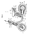
- Fig. 1 is a side view of an electric motorcycle 1 on which an axial gap dynamo-electric machine, which is an example of a dynamo-electric machine using a magnet according to an embodiment of the present invention, is mounted.
- the electric motorcycle 1 includes a head pipe 2 at the upper front of a vehicle body, and the head pipe rotatably accommodates a steering shaft, not shown, for changing the direction of the vehicle body therein.
- a handle supporting member 3 on which a handle 3a is fixed is mounted at the upper end of the steering shaft, and grips 4 are mounted to both ends of the handle 3a.
- the right (far side of Fig. 1) grip 4, not shown, constitutes a rotatable throttle grip.
- a pair of left and right front forks 5 are mounted to the head pipe 2 downward from the lower end thereof.
- a front wheel 6 is mounted via a front axle 7, and the front wheel 6 is rotatably supported by the front axle 7 in a state of being suspended by the front forks 5 in a damping manner.
- a pair of left and right vehicle body frames 11 each formed into a substantially L-shape in side view extend from the head pipe 2 rearwardly of the vehicle body.
- the vehicle body frames 11 are round pipes, and extend from the head pipe 2 rearward and obliquely downward from the head pipe 2, and then horizontally toward the rear so as to be formed substantially into the L-shape in side view.
- a pair of left and right seat rails 12 extend rearward and obliquely upward, and then the rear end sections 12a of the seat rails 12 are bent rearward along the shape of a seat 13.
- a battery 14 so as to be detachable, and the battery 14 accommodates a plurality of secondary chargeable batteries.
- a seat stay 15 formed into an inverted U-shape is welded so as to be inclined upward toward the front with respect to the vehicle body, and the seat 13 is disposed at the portion surrounded by the seat stay 15 and the left and the right seat rails 12 so as to be openable and closable, that is, so as to be capable of pivoting in the vertical direction about the front end of the seat 13.
- a rear fender 16 is mounted to the rear ends of the seat rails 12, and a tail lamp 17 is mounted to the rear surface of the rear fender 16.
- flash lamps (only one of them is shown in Fig. 1) 18 are mounted on the left and the right of the tail lamp 17.
- rear arm brackets 19 (only one of them is shown in Fig. 1) are welded to the horizontal portions of the pair of left and right vehicle body frames 11 below the seat 13, respectively, and the front ends of rear arms 20 are pivotably supported by the pair of left and right rear arm brackets 19 via a pivot shaft 21.
- a pair of left and right footsteps 24 (only one of them is shown in Fig. 1) are disposed below the horizontal portions of the left and the right vehicle body frames 11, respectively, and a side stand 25 is supported by the left rear arm 20 so as to be capable of rotating via a shaft 26 behind the footstep 24.
- the side stand 25 is urged toward the closing side by a return spring 27.
- a drive unit 29 including an axial gap electric motor 28 (hereinafter, may be referred simply as electric motor 28) connected to the rear wheel 22 for rotating the rear wheel 22 is mounted in the rear end section 20a of the rear arm 20.
- Fig. 2 is a cross-sectional view (partly in side view) taken along the line II-II in Fig. 1 for explaining the inside of the rear end section 20a of the rear arm 20.
- the rear wheel 22 is not shown.
- a gear cover 35 covers the right side surface of the rear end 20a of the rear arm 20, and the electric motor 28 that constitutes the drive unit 29, a planet gear speed reducer 36, a controller 37, and so on are integrally assembled within a space formed therein.
- the axial gap electric motor 28 includes, as shown in Fig. 2, a rotor 40 supported at the rear end section 20a of the rear arm 20 via bearings 38a, 38b so as to be rotatable about a center axis BO of the bearings 38a, 38b, and a stator 41 of substantially ring (doughnut) shape fixed to the inner surface of the rear end section 20a of the rear arm so as to oppose the rotor 40.
- the rotor 40 includes, as shown in Fig. 2, Fig. 3, and Fig. 4, a rotor yoke 42, and the rotor yoke 42 is shaped like a spinning top projecting toward the rear end section 20a of the rear arm 20.
- the rotor yoke 42 includes a ring-shaped portion 42a of a ring shape opposing the stator 41, a tapered portion 42b extending in a substantially tapered shape (substantially conical shape) from the inner peripheral edge of the ring-shaped portion 42a toward the rear end section 20a of the rear arm 20, a first cylindrical portion 42c extending from the side peripheral edge of the rear end section 20a of the rear arm of the tapered portion 42b toward the rear end section 20a along the center axis BO in the projecting manner, a ring-shaped portion 42d extending radially inwardly from the side peripheral edge of the cylindrical portion 42c on the side of the rear end section 20a of the rear arm, and a second cylindrical portion 42e extending from the inner peripheral edge of the ring-shaped portion 42d toward the rear end section 20a along the center axis BO in a projecting manner.
- the second cylindrical portion 42e is rotatably supported via the bearings 38a, 38b about the center axis BO, to construct a revolving shaft of the rotor 40. Therefore, the center of rotational axis of a revolving shaft 42e of the rotor 40 corresponds to the center axis BO of the bearings 38a, 38b.
- the rotor 40 is fixed to the ring-shaped portion 42a of the rotor yoke 42 on the surface opposing the stator, and is provided with a magnet 45 for magnetic field, being formed substantially into a circular shape (ring shape) which is coaxial with the center axis BO.
- a revolving shaft 46 is connected to the revolving shaft 42e of the rotor 40 at the end on the rear wheel side coaxially with the rotor 40 (revolving shaft 42e), and the revolving shaft 46 is rotatable integrally with the rotor 40.
- the planet gear speed reducer 36 is connected to the revolving shaft 46, and is assembled in the tapered portion 42b of the rotor yoke 42.
- the planet gear speed reducer 36 and the electric motor 28 are partly overlapped with each other in the direction of the width of the vehicle.
- the planet gear speed reducer 36 is connected to a rear axle 47 disposed coaxially with the revolving shaft 46, and has a function to reduce the speed of rotation (rotation of the revolving shaft 46) of the electric motor 28 and to transmit it to the rear axle 47.
- a nut 50 is detachably screwed on the extremity 47a of the rear axle 47 projecting from the gear cover 35, and the rear wheel 22 is mounted and fixed to the rear axle 47 by screwing the nut 50 thereon.
- the stator 41 is fixed to the rear end section 20a of the rear arm 20, and includes a layered stator yoke 60 formed by laminating disk-shaped or ring-shaped steel plates (in this embodiment, the ring-shaped steel plates are employed) along the direction of center axis, and a plurality of teeth 61 disposed substantially into a ring shape so as to oppose the magnet 45 at a predetermined gap, and each being formed of a laminated steel plate.
- the magnet 45 includes a plurality of magnetic poles 45a (N-pole) and 45b (S-pole) opposing the above-described plurality of teeth 61 disposed substantially in a circular shape with the intermediary of a gap along the direction of revolving shaft BO and disposed substantially in the shape of circle.
- the N-poles 45a and the S-poles45b are disposed alternately along the circumferential direction.
- the magnet 45 is provided with a plurality of inter-pole sections 45c extending from each of the adjacent magnetic poles os the plurality of magnetic poles (N-pole 45a and S-pole 45b) along the circumferential direction, and boundaries of the respective magnetic poles (boundaries between the adjacent N-poles and S-poles) Bm extends substantially along the radial direction substantially at the centers of the inter-pole sections 45c.
- Fig. 5 is an enlarged drawing showing the inter-pole section 45c shown in Fig. 3.
- the tooth-opposed surface of the inter-pole section 45c is recessed in a curved manner along the direction of the revolving shaft with respect to the tooth-opposed surfaces of the magnetic poles (the N-poles 45a and the S-poles 45b), that is, the inter-pole section 45c has a recessed tooth-opposed surface.
- the area of the recessed tooth-opposed surface of the inter-pole section 45c is smaller than those of the N-pole 45a and the S-pole 45b on both sides thereof.
- torque may be maintained substantially at a constant level in comparison with the case in which the recessed inter-pole sections are not present.
- the depth of the recessed portion of the inter-pole section 45c along the direction of the revolving shaft and the curvature radius of the curved recessed portion are set to values which provide a smooth variation of the magnetic flux, that will be described later.
- the magnet 45 (magnet poles 45a, 45b and the inter-pole section 45c) in the present embodiment is, for example, a resin magnet (bonded magnet), formed of resin (mixture) of mixed (compounded) magnet powder and binder resin into a ring shape by injection molding.
- a magnetic circuit is formed between the rotor 40 and the stator 41, and a magnetic flux supplied from the N-pole of the magnet 45 of the rotor 40 flows through the teeth 61 to the stator yoke 60, and then to the S-pole of the magnet 45 through other teeth 61.
- the teeth 61 to be excited may be shifted sequentially so that the rotor 40 is rotated with the magnet 45.
- Fig. 6A to Fig. 6C are drawings showing a positional relation between the rotor 40 and the teeth 61 (shown by chain double-dashed line) when the rotor 40 is rotated.
- the inter-pole sections 45c each having the tooth-opposed surface being set back with respect to the poles 45a and 45b are provided between the excited portions (N-pole 45a and S-pole 45b) of the magnet 45, the magnetic flux at the recessed inter-pole section 45c is decreased, and thus the magnetic flux changes smoothly when the N-pole 45a and 45b of the rotor 40 move from one predetermined tooth 61 to the next tooth 61.
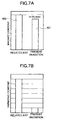
- Fig. 7A is a drawing showing a relationbetween the magnetic content M0 of the magnet in the related art in the case where torque is maintained at a constant value (in the case where the recessed inter-pole sections are not present) and the magnetic content M1 of the magnet 45 in the present embodiment (the vertical axis represents magnet content).
- Fig. 7B is a drawing showing a ratio between the distortion factor of the induced voltage (the amount of harmonic content) in the electric motor having the magnet in the related art (in the case in which the recessed inter-pole sections are not present) and the distortion factor of the induced voltage in the electric motor 28 in which the magnet 45 of the present embodiment is employed.
- the magnet content corresponding to the set back portion may be reduced (for example, approximately 11.4% can be reduced), which may contribute to reduction of the cost of the dynamo-electric machine.
- the distortion factor of the induced voltage in the electric motor 28 using the magnet 45 according to the present embodiment is reduced to about 1/7 in comparison with the distortion factor of the induced voltage in the electric motor using the magnet in the related art, whereby the induced voltage waveform due to mixed magnetic flux may be approximate to a sinusoidal wave.
- the recessed inter-pole sections 45c each having the tooth-opposed surface set back with respect to the magnetic poles 45a and 45b are provided between the N-pole 45a and S-pole 45b of the magnet 45, the induced voltage waveform corresponding to the mixed magnetic flux between the magnet 45 of the rotor 40 and teeth 61 may be approximate to a sinusoidal wave. Consequently, generation of torque ripple is restrained, and thus the smooth rotation of the rotor 40 is maintained, so that generation of vibrations and noise may be prevented.
- the plurality of magnetic poles 45a, 45b and the plurality of inter-pole sections 45c constituting the magnet 45 are formed by integrally molding using resin mixture, for example, of magnet powder and binder resin into a ring shape by injection molding.
- the recessed inter-pole sections 45c are provided by setting back the portions between the N-poles 45a and the S-poles 45b into a curved shape.
- the configuration of the recessed portion are not limited to the curved shape, and may be any shape such as a rectangular shape.
- the recessed inter-pole sections 45c are provided between the N-pole 45a and the S-poles 45b for changing the magnetic flux smoothly when the N-poles 45a and the S-poles 45b of the rotor 40 move from one tooth 61 to the next tooth 61.
- the present invention is not limited thereto.
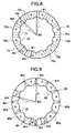
- FIG. 8 is a drawing showing a magnet 70 according to a first modification of the present embodiment.
- the magnet 70 is a resin magnet formed integrally, for example, by injection molding, and is provided with a plurality of magnetic poles 70a (N-pole) and 70b (S-pole) opposing the plurality of teeth 61 disposed substantially into the above-described shape of a circle with the intermediary of a gap along the direction of the revolving shaft BO and disposed substantially into the shape of a circle.
- the N-poles 70a and the S-poles 70b are disposed alternately along the circumferential direction.
- the magnet 70 is provided with the plurality of inter-pole sections 70c extending from each of the adjacent magnetic poles of the plurality of magnetic poles (N-pole 70a and S-pole 70b) along the circumferential direction, and boundaries of the respective magnetic poles (boundaries between the adjacent N-poles and S-poles) Bm each extending substantially along the radial direction are substantially at centers of the inter-pole sections 70c.
- the length L1 from the revolving shaft BO to the inner periphery 71 of the inter-pole section 70c along the radial direction is longer than the length L2 to the inner peripheries 72 of the magnetic poles 70a and 70b, and the radial width W1 of the inter-pole section 70c is shorter than the radial width W2 of the magnetic poles 70a and 70b.
- the inner periphery 71 is formed into a recessed inner periphery by setting back the inner periphery 71 of the inter-pole section 70c with respect to the inner peripheries 72 of the respective magnetic poles 70a and 70b toward an outer periphery 73 of the inter-pole section 70c in a rectangular shape.
- the inner peripheries 72 of the magnet poles 70a and 70b are projecting toward the revolving shaft BO in a rectangular shape.
- the induced voltage waveform corresponding to the mixed magnetic fluxes between the magnet 70 of the rotor 40 and the teeth 61 may be approximated to a sinusoidal waveform, and thus generation of torque ripple is restrained so that smooth rotation of the rotor 40 may be maintained and generation ofvibrations/noise may be prevented.
- the plurality of magnet poles 70a, 70b and the plurality of inter-pole sections 70c that constitute the magnet 70 are formed integrally of resin mixture of magnet powder and binder resin, for example, into a ring shape by injection molding.
- torque ripple reducing effect is achieved without increasing the number of components of the rotor 40 while maintaining assemblability of the rotor 40 at a high level.
- Fig. 9 is a drawing showing a magnet 80 according to a second modification of the present embodiment.
- the magnet 80 is also a resin magnet formed integrally, for example, by injection molding, and is provided with a plurality of magnetic poles 80a (N-poles) and 80b (S-poles) which are similar to the magnetic poles 70a and 70b shown in Fig. 8, and a plurality of inter-pole sections 80c, and boundaries of the respective magnetic poles (boundaries between the adjacent N-poles and S-poles) Bm extends substantially along the radial direction substantially at the centers of the inter-pole sections 80c.
- the length L3 from the revolving shaft BO to the inner periphery 81 of the inter-pole section 80c along the radial direction is longer than the length L4 to the inner peripheries 82 of the magnetic poles 80a and 80b, and the radial width W3 of the inter-pole section 80c is shorter than the radial width W4 of the respective magnetic poles 80a and 80b.
- the inner periphery 81 of the inter-pole 80c is set back toward an outer periphery 83 of the inter-pole section 80c with respect to inner peripheries 82 of the respective magnetic poles 80a and 80b, and the inner peripheries 82 of the respective magnetic poles 80a and 80b are projected in a curved manner toward the revolving shaft BO.
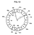
- Fig. 10 is a drawing showing a magnet 90 according to a third modification of the present embodiment.
- the magnet 90 is also a resin magnet integrally formed, for example, by injection molding, and is provided with a plurality of magnetic poles 90a (N-poles) and 90b (S-poles) and the plurality of inter-pole sections 90c which are substantially the same as in the first and the second modifications, and the boundaries of the respective magnetic poles (boundaries between the adjacent N-poles and S-poles) Bm extends substantially along the radial direction substantially at the centers of the inter-pole sections 90c.
- the length L5 from the revolving shaft BO to the inner periphery 91 of the inter-pole section 90c along the radial direction is longer than the length L6 to inner peripheries 92 of the magnetic poles 90a and 90b, and the radial width W5 of the inter-pole section 90c is shorter than the radial width W6 of the respective magnetic poles 90a and 90b.
- the inner periphery 91 of the inter-pole section 90c is recessed toward the outer periphery 93 of the inter-pole section 90c with respect to the inner peripheries 92 of the respective magnetic poles 90a and 90b substantially into a V-shape, and the inner peripheries 92 of the respective magnetic poles 90a and 90b are projected toward the revolving shaft BO substantially in an inverted V-shape.
- FIG. 11 is a drawing showing a magnet 100 according to a fourth modification of the present embodiment.
- the magnet 100 is a resin magnet integrally formed, for example, by injection molding, and is provided with a plurality of magnetic poles 100a (N-poles), 100b (S-poles), and a plurality of inter-poles sections 100c , which are substantially the same as the first to the third modifications, and boundaries of the respective magnetic poles (boundaries between the adj acent N-poles and S-poles) Bm extends substantially along the radial direction substantially at the centers of the inter-pole sections 100c.
- the length L7 from the revolving shaft BO to the outer periphery 101 of the inter-pole section 100c along the radial direction is shorter than the length L8 to outer peripheries 102 of the respective magnetic poles 100a and 100b, and the radial width W7 of the inter-pole section 100c is shorter than the radial widths W8 of the respective magnetic poles 100a and 100b.
- the outer periphery 101 of the inter-pole section 100c is set back toward the inner periphery 103 of the inter-pole section 100c in a substantially rectangular shape with respect to the outer peripheries 102 of the respective magnetic poles 100a and 100b and the outer peripheries 102 of the respective magnetic poles 100a and 100b are projected from the revolving shaft BO toward the outer periphery in a substantially rectangular shape.
- the outer periphery 101 of the inter-pole section 100c is set back with respect to the outer peripheries 102 of the respective magnetic poles 100a and 100b instead of setting back the inner periphery 103 of the inter-pole section 100c.
- the magnetic flux at the recessed inter-pole section 100c is reduced, and thus the magnetic flux in association with rotation of the rotor 40 may be changed smoothly, whereby the same effect as the first to third modifications can be obtained.
- the magnet according to the present invention is used for the axial gap dynamo-electric machine mounted to the motorcycle.
- the present invention is not limited thereto, and may be applied to the axial gap dynamo-electric machine which is mounted to other apparatus/equipment, and the same effects as described above will be achieved.
- the present invention is not limited thereto, and may be applied to so-called electric generator, which allows a coil to generate electromotive force by rotating the rotor from the outside.
- the magnet according to the present invention has been described as a resin magnet integrally formed by injection molding.
- the present invention is not limited thereto, and may be, for example, a sintered magnet or the like.
- the present invention is not limited to the above-described embodiments, and may be embodied in other modes by modifying as needed within the scope of the present invention.
Landscapes
- Engineering & Computer Science (AREA)
- Power Engineering (AREA)
- Transportation (AREA)
- Mechanical Engineering (AREA)
- Life Sciences & Earth Sciences (AREA)
- Sustainable Development (AREA)
- Sustainable Energy (AREA)
- Permanent Field Magnets Of Synchronous Machinery (AREA)
Applications Claiming Priority (3)
| Application Number | Priority Date | Filing Date | Title |
|---|---|---|---|
| JP2002237633 | 2002-08-16 | ||
| JP2002237633 | 2002-08-16 | ||
| PCT/JP2003/010387 WO2004017489A1 (ja) | 2002-08-16 | 2003-08-15 | 回転電機のマグネット |
Publications (2)
| Publication Number | Publication Date |
|---|---|
| EP1553678A1 true EP1553678A1 (de) | 2005-07-13 |
| EP1553678A4 EP1553678A4 (de) | 2007-05-02 |
Family
ID=31884442
Family Applications (1)
| Application Number | Title | Priority Date | Filing Date |
|---|---|---|---|
| EP03788130A Withdrawn EP1553678A4 (de) | 2002-08-16 | 2003-08-15 | Magnet einer elektrischen dynamomaschine |
Country Status (7)
| Country | Link |
|---|---|
| US (1) | US7116027B2 (de) |
| EP (1) | EP1553678A4 (de) |
| JP (1) | JPWO2004017489A1 (de) |
| CN (1) | CN1675813A (de) |
| AU (1) | AU2003266503A1 (de) |
| TW (1) | TWI256190B (de) |
| WO (1) | WO2004017489A1 (de) |
Families Citing this family (10)
| Publication number | Priority date | Publication date | Assignee | Title |
|---|---|---|---|---|
| EP1553678A4 (de) | 2002-08-16 | 2007-05-02 | Yamaha Motor Co Ltd | Magnet einer elektrischen dynamomaschine |
| TWI283103B (en) * | 2004-02-06 | 2007-06-21 | Yamaha Motor Co Ltd | Rotating electric machine and electrically driven vehicle |
| JP4802014B2 (ja) * | 2005-08-05 | 2011-10-26 | ヤマハ発動機株式会社 | 回転電機を搭載する鞍乗型車両 |
| JP2008043031A (ja) * | 2006-08-04 | 2008-02-21 | Mabuchi Motor Co Ltd | リング形状界磁マグネットに薄肉部を形成した小型モータ |
| JP5309609B2 (ja) * | 2008-02-29 | 2013-10-09 | ダイキン工業株式会社 | アキシャルギャップ型回転電機及び界磁子用コア |
| TWI385899B (zh) * | 2008-12-25 | 2013-02-11 | Metal Ind Res & Dev Ct | 永磁式電機之轉子結構及其製造方法 |
| CN103138518A (zh) * | 2011-11-28 | 2013-06-05 | 台达电子工业股份有限公司 | 三相轴向磁通马达及其磁路调控方法 |
| JP2014060837A (ja) | 2012-09-14 | 2014-04-03 | Yamaha Motor Co Ltd | アキシャルギャップ型回転電機、同回転電機を備えた電動車椅子及び電動自転車 |
| US20140175931A1 (en) * | 2012-12-21 | 2014-06-26 | Samsung Electro-Mechanics Co., Ltd. | Axial flux permanent magnet motor |
| WO2021145136A1 (ja) * | 2020-01-14 | 2021-07-22 | ヤマハ発動機株式会社 | アキシャルギャップ型モータ |
Family Cites Families (24)
| Publication number | Priority date | Publication date | Assignee | Title |
|---|---|---|---|---|
| US3219861A (en) * | 1961-03-06 | 1965-11-23 | Printed Motors Inc | Alternating-current generator |
| US3310693A (en) * | 1964-02-04 | 1967-03-21 | Gray & Huleguard Inc | Magnetic coupling |
| JPS505923Y1 (de) * | 1969-12-27 | 1975-02-20 | ||
| JPS5619516B2 (de) | 1973-05-21 | 1981-05-08 | ||
| CA1004275A (en) * | 1974-04-04 | 1977-01-25 | Canadian General Electric Company Limited | Permanent magnet synchronous dynamoelectric machine |
| JPS5253204A (en) * | 1975-10-24 | 1977-04-28 | Hitachi Metals Ltd | Permanent magnet type revolving machine |
| JPS5553164A (en) * | 1978-10-14 | 1980-04-18 | Sony Corp | Permanent magnet rotor |
| JPS59139842A (ja) * | 1983-01-31 | 1984-08-10 | Seiko Epson Corp | 回転電機用多極着磁磁石 |
| US4634906A (en) * | 1983-07-28 | 1987-01-06 | Michel Grosjean | Multiphase motor with magnetized rotor having N pairs of poles with axial magnetization |
| JPS6430444A (en) * | 1987-07-23 | 1989-02-01 | Matsushita Electric Works Ltd | Rotor magnet |
| GB8817760D0 (en) * | 1988-07-26 | 1988-09-01 | Rolls Royce Plc | Electrical power generator |
| JPH02252970A (ja) * | 1989-03-27 | 1990-10-11 | Sawafuji Electric Co Ltd | スタータのロータおよびその製造方法 |
| US5206556A (en) * | 1989-08-29 | 1993-04-27 | Mabuchi Motor Co., Ltd. | Field magnet for miniature motors |
| IT1261598B (it) * | 1993-09-30 | 1996-05-23 | Gate Spa | Motore elettrico a magneti permanenti con coppia di riluttanza ridotta |
| US6037696A (en) * | 1993-12-29 | 2000-03-14 | Samot Engineering (1992) Ltd. | Permanent magnet axial air gap electric machine |
| GB9510994D0 (en) * | 1995-05-31 | 1995-07-26 | Turbo Genset The Company Ltd | Rotary electrical machines |
| JP3500822B2 (ja) * | 1995-12-26 | 2004-02-23 | アイシン・エィ・ダブリュ株式会社 | 永久磁石式同期電動機 |
| JP3017953B2 (ja) * | 1996-07-24 | 2000-03-13 | 株式会社東芝 | 電動機の回転子及びその製造方法 |
| JP2000156947A (ja) * | 1998-11-17 | 2000-06-06 | Yukio Kinoshita | 磁石式電動機及び発電機 |
| JP2001037124A (ja) * | 1999-07-27 | 2001-02-09 | Hitachi Metals Ltd | 回転子 |
| JP2001057753A (ja) | 1999-08-12 | 2001-02-27 | Mitsubishi Heavy Ind Ltd | アキシャルギャップ型モータ |
| US6713922B2 (en) * | 2000-12-29 | 2004-03-30 | Otis Elevator Company | Integrally skewed permanent magnet for use in an electric machine |
| JP3304969B2 (ja) * | 2001-07-17 | 2002-07-22 | 株式会社デンソー | 車両用制振発電電動機 |
| EP1553678A4 (de) | 2002-08-16 | 2007-05-02 | Yamaha Motor Co Ltd | Magnet einer elektrischen dynamomaschine |
-
2003
- 2003-08-15 EP EP03788130A patent/EP1553678A4/de not_active Withdrawn
- 2003-08-15 WO PCT/JP2003/010387 patent/WO2004017489A1/ja not_active Ceased
- 2003-08-15 JP JP2004528889A patent/JPWO2004017489A1/ja active Pending
- 2003-08-15 CN CNA038191296A patent/CN1675813A/zh active Pending
- 2003-08-15 TW TW092122536A patent/TWI256190B/zh not_active IP Right Cessation
- 2003-08-15 AU AU2003266503A patent/AU2003266503A1/en not_active Abandoned
-
2005
- 2005-02-16 US US11/058,921 patent/US7116027B2/en not_active Expired - Fee Related
Also Published As
| Publication number | Publication date |
|---|---|
| TW200404398A (en) | 2004-03-16 |
| TWI256190B (en) | 2006-06-01 |
| US7116027B2 (en) | 2006-10-03 |
| US20050174003A1 (en) | 2005-08-11 |
| AU2003266503A1 (en) | 2004-03-03 |
| EP1553678A4 (de) | 2007-05-02 |
| CN1675813A (zh) | 2005-09-28 |
| JPWO2004017489A1 (ja) | 2005-12-08 |
| WO2004017489A1 (ja) | 2004-02-26 |
Similar Documents
| Publication | Publication Date | Title |
|---|---|---|
| US7151335B2 (en) | Permanent magnet rotating electric machine and electric car using the same | |
| US20060103263A1 (en) | Rotating electric machine | |
| US7462968B2 (en) | Electric wheel | |
| US8053942B2 (en) | Axial gap motor | |
| CN102447318B (zh) | 多间隙旋转电机 | |
| EP1895638A2 (de) | Rotationselektrogerät | |
| EP1553678A1 (de) | Magnet einer elektrischen dynamomaschine | |
| EP1795438A1 (de) | Radmontierte vorrichtung mit doppelfunktion als gleichstromerzeuger in der nabe für ein fahrrad und als motor für hilfsantrieb | |
| JP2003506005A (ja) | 電気駆動装置(選択可能な形態) | |
| JP3964378B2 (ja) | 車両用回転電機 | |
| US20240364159A1 (en) | Overmolded rotor structure | |
| US20220393559A1 (en) | Overmolded rotor structure | |
| JP3994105B2 (ja) | アキシャルギャップ型回転電機 | |
| US20240022126A1 (en) | Rotor magnet retention structure in brushless motor | |
| JPWO2004015842A1 (ja) | 回転電機 | |
| JPH05268752A (ja) | 車両用交流発電機 | |
| JPH1141888A (ja) | 同期回転機 | |
| JPH0779553A (ja) | 多機能電磁回転装置 | |
| CN120237848A (zh) | 马达及电动车 |
Legal Events
| Date | Code | Title | Description |
|---|---|---|---|
| PUAI | Public reference made under article 153(3) epc to a published international application that has entered the european phase |
Free format text: ORIGINAL CODE: 0009012 |
|
| 17P | Request for examination filed |
Effective date: 20050207 |
|
| AK | Designated contracting states |
Kind code of ref document: A1 Designated state(s): AT BE BG CH CY CZ DE DK EE ES FI FR GB GR HU IE IT LI LU MC NL PT RO SE SI SK TR |
|
| AX | Request for extension of the european patent |
Extension state: AL LT LV MK |
|
| DAX | Request for extension of the european patent (deleted) | ||
| A4 | Supplementary search report drawn up and despatched |
Effective date: 20070403 |
|
| 17Q | First examination report despatched |
Effective date: 20081118 |
|
| STAA | Information on the status of an ep patent application or granted ep patent |
Free format text: STATUS: THE APPLICATION IS DEEMED TO BE WITHDRAWN |
|
| 18D | Application deemed to be withdrawn |
Effective date: 20090331 |