EP1554055B1 - Sprühvorrichtung betätigt durch eine bewegung zwischen einem behälter und einer umgebenden hülle - Google Patents
Sprühvorrichtung betätigt durch eine bewegung zwischen einem behälter und einer umgebenden hülle Download PDFInfo
- Publication number
- EP1554055B1 EP1554055B1 EP03795955A EP03795955A EP1554055B1 EP 1554055 B1 EP1554055 B1 EP 1554055B1 EP 03795955 A EP03795955 A EP 03795955A EP 03795955 A EP03795955 A EP 03795955A EP 1554055 B1 EP1554055 B1 EP 1554055B1
- Authority
- EP
- European Patent Office
- Prior art keywords
- container
- spray device
- axis
- liquid
- casing
- Prior art date
- Legal status (The legal status is an assumption and is not a legal conclusion. Google has not performed a legal analysis and makes no representation as to the accuracy of the status listed.)
- Expired - Lifetime
Links
Images


Classifications
-
- A—HUMAN NECESSITIES
- A45—HAND OR TRAVELLING ARTICLES
- A45D—HAIRDRESSING OR SHAVING EQUIPMENT; EQUIPMENT FOR COSMETICS OR COSMETIC TREATMENTS, e.g. FOR MANICURING OR PEDICURING
- A45D34/00—Containers or accessories specially adapted for handling liquid toiletry or cosmetic substances, e.g. perfumes
- A45D34/02—Scent flasks, e.g. with evaporator
-
- B—PERFORMING OPERATIONS; TRANSPORTING
- B05—SPRAYING OR ATOMISING IN GENERAL; APPLYING FLUENT MATERIALS TO SURFACES, IN GENERAL
- B05B—SPRAYING APPARATUS; ATOMISING APPARATUS; NOZZLES
- B05B11/00—Single-unit hand-held apparatus in which flow of contents is produced by the muscular force of the operator at the moment of use
- B05B11/0005—Components or details
- B05B11/0037—Containers
- B05B11/0038—Inner container disposed in an outer shell or outer casing
-
- B—PERFORMING OPERATIONS; TRANSPORTING
- B05—SPRAYING OR ATOMISING IN GENERAL; APPLYING FLUENT MATERIALS TO SURFACES, IN GENERAL
- B05B—SPRAYING APPARATUS; ATOMISING APPARATUS; NOZZLES
- B05B11/00—Single-unit hand-held apparatus in which flow of contents is produced by the muscular force of the operator at the moment of use
- B05B11/01—Single-unit hand-held apparatus in which flow of contents is produced by the muscular force of the operator at the moment of use characterised by the means producing the flow
- B05B11/10—Pump arrangements for transferring the contents from the container to a pump chamber by a sucking effect and forcing the contents out through the dispensing nozzle
- B05B11/1042—Components or details
- B05B11/1052—Actuation means
-
- B—PERFORMING OPERATIONS; TRANSPORTING
- B05—SPRAYING OR ATOMISING IN GENERAL; APPLYING FLUENT MATERIALS TO SURFACES, IN GENERAL
- B05B—SPRAYING APPARATUS; ATOMISING APPARATUS; NOZZLES
- B05B11/00—Single-unit hand-held apparatus in which flow of contents is produced by the muscular force of the operator at the moment of use
- B05B11/01—Single-unit hand-held apparatus in which flow of contents is produced by the muscular force of the operator at the moment of use characterised by the means producing the flow
- B05B11/10—Pump arrangements for transferring the contents from the container to a pump chamber by a sucking effect and forcing the contents out through the dispensing nozzle
- B05B11/1042—Components or details
- B05B11/1073—Springs
- B05B11/1074—Springs located outside pump chambers
-
- B—PERFORMING OPERATIONS; TRANSPORTING
- B05—SPRAYING OR ATOMISING IN GENERAL; APPLYING FLUENT MATERIALS TO SURFACES, IN GENERAL
- B05B—SPRAYING APPARATUS; ATOMISING APPARATUS; NOZZLES
- B05B11/00—Single-unit hand-held apparatus in which flow of contents is produced by the muscular force of the operator at the moment of use
- B05B11/01—Single-unit hand-held apparatus in which flow of contents is produced by the muscular force of the operator at the moment of use characterised by the means producing the flow
- B05B11/10—Pump arrangements for transferring the contents from the container to a pump chamber by a sucking effect and forcing the contents out through the dispensing nozzle
- B05B11/1042—Components or details
- B05B11/1073—Springs
- B05B11/1077—Springs characterised by a particular shape or material
-
- A—HUMAN NECESSITIES
- A45—HAND OR TRAVELLING ARTICLES
- A45D—HAIRDRESSING OR SHAVING EQUIPMENT; EQUIPMENT FOR COSMETICS OR COSMETIC TREATMENTS, e.g. FOR MANICURING OR PEDICURING
- A45D34/00—Containers or accessories specially adapted for handling liquid toiletry or cosmetic substances, e.g. perfumes
- A45D2034/005—Containers or accessories specially adapted for handling liquid toiletry or cosmetic substances, e.g. perfumes with a cartridge
-
- A—HUMAN NECESSITIES
- A45—HAND OR TRAVELLING ARTICLES
- A45D—HAIRDRESSING OR SHAVING EQUIPMENT; EQUIPMENT FOR COSMETICS OR COSMETIC TREATMENTS, e.g. FOR MANICURING OR PEDICURING
- A45D2200/00—Details not otherwise provided for in A45D
- A45D2200/05—Details of containers
- A45D2200/054—Means for supplying liquid to the outlet of the container
- A45D2200/057—Spray nozzles; Generating atomised liquid
Definitions
- the invention relates to a spray device with combined drive, that is to say an atomizer or aerosol intended to spray a liquid, particularly a fragrance, a perfume or an eau de toilette contained in a bottle, this spray bottle being equipped with a propulsion member operating according to the member according to the invention.
- aerosols which comprise a propellant gas released through the opening of the valve shutter of a valve to drive the liquid
- atomizers the pump of which propels the liquid via the pressure mechanically exerted by a piston.
- the "valve - valve shutter” or “pump - piston” assemblies are hereinafter referred to as propulsion member.
- propulsion member the spray bottle is equipped with a push-button which the user presses in order to introduce into the flow duct of the propulsion member the liquid contained in a bottle.
- Spraying is in fine droplets through an outlet nozzle mounted on the push-button.
- an atomizer lever adopting the form of a trigger which actuates spraying.
- This type of spray bottle as illustrated for example in patents EP 0 449 046 or EP 0 734 783, finds applications in the household or hygiene sector (for cleaning windows, deodorizing, etc.).
- document FR 276-7-799 proposes packaging for a product in which the outlet nozzle is kept fixed and the push-button is connected to the nozzle by a flexible pipe.
- document WO 94/05593 discloses a pump dispenser with movable bottle, in which a push bar is hinged and the bottle follows the course of a radius extending form the hinge, and is caused to rise by a cam.
- the invention sets out to produce a look of this type by virtue of another approach that also makes it possible to simplify assembly. To do this, it is proposed that the pressure and spraying generating movement be actuated not by pressing the push-button but by moving the bottle laterally in a rotational movement coupled with a translational movement.
- a liquid spray device with combined drive equipped with a liquid propulsion member that has a main axis of translation coupled, on the one hand, to a spray member comprising a nozzle having an axis of diffusion and, on the other hand, to a container containing the liquid.
- This liquid spray device comprises a rigid casing which partially surrounds the container and which extends roughly in a main plane containing the axis of translation.
- It also comprises a resilient pivoting head connecting the spray member and the casing, and a region of sliding between the container and the casing, so that manual thrust exerted laterally on the container in the main plane of the casing causes, through a combination of the action of the sliding region and of the pivoting head, actuation of the propulsion member to spray the liquid and a movement of the container, with respect to the casing, in a pendular movement about an axis of pivoting located near the propulsion member and which pendular movement, by conversion with respect to the pivoting head, generates translation of the propulsion member along said axis of translation to actuate the spraying of the liquid through the nozzle
- the movement is converted by the bottle bearing on the casing along at least one linear or curved portion, for example in the form of a spiral or ellipse, or by an articulation with two axes of rotation, that is to say of the rod-crank type.
- this spray bottle may comprise two half-shells assembled to form a shell to clad the bottle.
- the shell has at least one stop for the actuating member and a slide which produces contact with a region of the bottle, and two openings, an opening for the diffusion of the liquid sprayed by the nozzle and an opening for access to the bottle which opening is formed by a cut-out on part of the shell, the cut-out and the slide being arranged in such a way that pressure exerted on the bottle through this cut-out causes the region of contact of the bottle to move along the slide.
- Another aspect of the invention relates to the problem posed by dimensional tolerances, particularly when the bottle is made of glass, because the bottle needs to be held firmly in position. Taking the existence of these tolerances into consideration makes it possible to produce a spray bottle which can operate with bottles the dimensions of which vary according to these tolerances.
- the invention proposes a resilient pivoting head coupled to the actuating member, of the push-button type, or which can be substituted for the latter through the incorporation of the means of connection to the liquid propulsion member and to the nozzle duct.
- the pivoting head bears around an articulation allowing the head to turn about an axis parallel to the axis of diffusion.
- the articulation is produced by a plugging-together of the male-female variety providing connection and guidance of the pivoting head on the shell.
- Such a head comprises a guide and axial abutment body for the propulsion member, a guide for orientating the nozzle during assembly, and a spring part, for example elastic arms which bear on shoulders of the bottle.
- the spring part then has a dual role:
- the pivoting head is made of a resilient thermoplastic, for example polyoxymethylene or polypropylene and is preferably obtained by injection molding.
- the invention advantageously allows the use of interchangeable refill cartridges comprising a bottle, of modest cost.
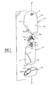
- a spray bottle according to the invention comprises two cladding half-shells 1a and 1b, which meet in a plane which is transverse with respect to the main longitudinal axis X'X.
- the half-shells have appreciably different sizes in the example illustrated, the upper half-shell having a spray opening 2 on a main face Fa through which a liquid can be sprayed in fine droplets.
- the half-shells have molded-in assembly elements: retaining tabs 10a on one half-shell which are associated with recesses 10b formed on the other half-shell.
- the half-shells are cut to form main faces with upper 10c and lower 10d inclined sides.
- the cladding is intended to envelop a glass bottle 3 the neck 4 of which is capped with a band 5 of the pump 50 the axis of translation of which, when not in use, coincides approximately with the axis X'X.
- the bottle has a shape which overall is parallelepipedal comprising two longitudinal main faces 4a and 4b extending in a main plane P and connected by two lateral faces 4c with continuous curvature.
- a protruding glass portion 6 extends symmetrically, from one lateral face 4c, along the longitudinal faces to cut off a triangle shape.
- the protruding portion 6 has a channel 7 connecting with the rest of the bottle.
- the pump 50 propels the liquid contained in the bottle 3 by coupling to a spray push-button 9 comprising a nozzle 11 having an axis of diffusion Y'Y perpendicular to the main axis X'X.
- the push-button is housed in a pivoting head 13 which has an orifice 14 and two elastic lateral arms 15 intended to bear on the bottle 3.
- the resilient pivoting head 13 is able to absorb dimensional tolerances.
- Such a head forms a guiding or axial abutment body for the push-button, and a guide for orientating the nozzle 11 via the rim of the orifice 14 at the time of assembly.
- the spray bottle has the configuration showed in the perspective view of figure 2a.
- the inclined sides 10c and 10d form a cut-out on each main face, of a size calculated to allow access to the protruding portion 6 of the bottle.
- the lower channel 7b of the protruding portion rests, via shoes 7c, on the inclined side 10d forming a sliding ramp.
- a lateral thrust F ⁇ 1 (figures 2b and 2c) is exerted on the bottle through this cut-out and causes the region of contact of the bottle to move along the slide on the protruding portion 6 of the bottle 3.
- the bottle moves sideways, bearing against the slide and in translation along the axis X'X (arrow F ⁇ 2 , , figure 2c) because of the holding of the push-button, to form a movement of the pendular type about an instantaneous axis of pivoting located near the pump 50 and which, by conversion of movement, causes translation along the axis X'X.
- the pump is then actuated and propels the liquid to the push-button 9 held in position by an articulation stop between the head and the half-shell (see figure 3).
- the liquid is diffused through the nozzle 11 and the orifice 14.
- figure 3 more especially shows:
- the articulation formed allows the head to turn about an axis parallel to the axis of diffusion Y'Y.
- the articulation provides the connection and guidance between the shell and the pivoting head.
- the elastic arms 15 return to the bottle to its position after use, with the creation of an axial clearance on the push-button, guaranteeing pump sealing.
- the arms compensate for the dimensional tolerances of the glass by holding the bottle firmly in place as the result of precompression exerted on the bottle during its placement.
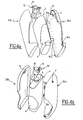
- the spray bottle comprises two half-shells, a front one 20a and a rear one 20b, which meet in a plane formed in the main plane P, the glass bottle 3 and the pivoting head 13.
- the pivoting head incorporates the means of connection to the propulsion pump and to the duct of the liquid propulsion duct nozzle so that the pivoting head acts as a push-button.
- Figure 4a more particularly shows the internal appearance of the front half-shell 20a which is equipped with the diffusion opening 2, and with tabs 10a for fixing to the other half-shell.
- Figure 4b shows the inside of the rear half-shell 20b equipped with the protrusion 16 for housing the wrist pin 18 of the pivoting head 13.
- the invention is not restricted to the exemplary embodiments described and depicted.
- the half-shells made of polypropylene or of polyethylene terephthalate or other thermoplastics.
- the pivoting head is made of a resilient thermoplastic, for example polyoxymethylene, and is obtained preferably by injection-molding.
- the propulsion member may be a pump, a valve or any suitable pressure means known to those skilled in the art.
- the liquid to be sprayed may be chosen from a cosmetic product, for example a cosmetic oil, a perfume and a skin-soothing product.
Landscapes
- Containers And Packaging Bodies Having A Special Means To Remove Contents (AREA)
- Catching Or Destruction (AREA)
- Nozzles (AREA)
Claims (15)
- Flüssigkeitssprühvorrichtung mit kombiniertem Antrieb, ausgestattet mit einem Flüssigkeitsantriebsteil (50), welches eine einerseits mit einem Sprühteil (9), welches eine Düse (11) mit einer Diffusionsachse (Y'Y) umfasst, und andererseits mit einem Behälter (3), welcher die Flüssigkeit enthält, gekoppelte Haupttranslationsachse (X'X) aufweist, wobei die Flüssigkeitssprühvorrichtung ein festes Gehäuse (1 a, 1 b; 20a, 20b), welches den Behälter (3) teilweise umgibt und welches sich ungefähr in einer Hauptebene (P), welche die Translationsachse (X'X) aufweist, erstreckt,
dadurch gekennzeichnet,
dass es ferner einen elastischen schwenkbaren Kopf (13), welcher das Sprühteil (9) und das Gehäuse (1 a, 1 b; 20a, 20b) verbindet, und einen Gleitbereich (7, 10d) zwischen dem Behälter (3) und dem Gehäuse (1a, 1 b; 20a, 20b) umfasst, so dass ein in der Hauptebene (P) des Gehäuses auf den Behälter lateral ausgeübter manueller Schub (F1) durch eine Kombination der Bewegung des Gleitbereichs (10d) und des schwenkbaren Kopfes (13) eine Betätigung des Antriebsteils (50) zum Sprühen der Flüssigkeit bewirkt, und eine Bewegung des Behälters in Bezug zu dem Gehäuse in einer Pendelbewegung um eine Schwenkachse, welche in der Nähe des Antriebsteils (50) angeordnet ist, bewirkt, und wobei die Pendelbewegung durch Umsetzung in Bezug auf den schwenkbaren Kopf eine Translation des Antriebsteils (50) entlang der Translationsachse (X'X) erzeugt, um das Sprühen von Flüssigkeit durch die Düse (11) auszulösen. - Sprühvorrichtung nach Anspruch 1, in welcher die Bewegung durch die Lagerung eines vorstehenden Abschnitts (6) des Behälters (3) auf dem Gehäuse entlang des Gleitbereichs, welcher durch eine lineare (10d) oder gekrümmte Steigung des Gehäuses ausgebildet ist, oder durch ein Gelenk mit zwei Rotationsachsen umgesetzt wird.
- Sprühvorrichtung nach Anspruch 2, wobei das Gehäuse zwei Halbschalen (1a, 2b; 20a, 20b) umfasst, welche durch Verriegelungsmittel (10a, 10b) zusammengesetzt sind, um eine Hülle zum Verkleiden des Behälters (3) auszubilden, wobei die Hülle mindestens einen Anschlag (16, 19) für das verbindende Teil (13), die bezüglich der Hauptachsen ziemlich geneigte Rampe (10d), und zwei Öffnungen, eine Öffnung (2) zur Diffusion der durch die Düse (11) gesprühten Flüssigkeit und eine Öffnung für einen Zugriff auf den Behälter (3), umfasst, wobei die Öffnung durch einen Ausschnitt (10) an einem Teil der Hülle ausgebildet ist, wobei die Größe des Ausschnitts berechnet ist, um den Zugriff zu dem hervorstehenden Abschnitt (6) des Behälters (3) zu ermöglichen, so dass ein durch diesen Ausschnitt auf den Behälter ausgeübter Druck bewirkt, dass ein Kontaktbereich (7c) des Behälters (3) sich entlang der Rampe (10d) bewegt.
- Sprühvorrichtung nach einem der vorangegangenen Ansprüche, wobei der Anschlag (16, 19) zum Anlenken an und Aufclipsen auf den Sprühteil (9) ausgebildet ist.
- Sprühvorrichtung nach Anspruch 3, wobei sich der Kontaktbereich aus einer Gleitrampe (10d) ergibt, die in dem Ausschnitt (10) ausgebildet ist, welcher eine Verbindungsbahn (7) des vorstehenden Abschnitts (6) des Behälters (3) zugeordnet ist.
- Sprühvorrichtung nach einem der vorangegangenen Ansprüche 3-5, wobei die Ebene, wo sich die Halbschalen (1 a, 1 b) treffen, ungefähr parallel zu der Längsachse des Behälter (3) ist.
- Sprühvorrichtung nach einem der Ansprüche 3-5, wobei die Ebene, in der sich die Halbschalen (20a, 20b) treffen, ungefähr senkrecht zu der Längsachse des Behälters (3) ist.
- Sprühvorrichtung nach einem der vorangegangenen Ansprüche 3-7, wobei die Halbschalen aus Polypropylen oder Polyethylenterephthalat gefertigt sind.
- Sprühvorrichtung nach einem der vorangegangenen Ansprüche, wobei der Behälter aus Glas gefertigt ist, das Betätigungsteil ein Druckknopf (9) ist, und das Verbindungsteil ein mit dem Druckknopf gekoppelter elastischer schwenkbarer Kopf (13) ist.
- Sprühvorrichtung nach einem der vorangegangenen Ansprüche, wobei der schwenkbare Kopf (13) durch Miteinbeziehen der Verbindungsmittel zu der Antriebspumpe (50) und zu dem Kanal der Düse (11) als ein Druckknopf wirkt.
- Sprühvorrichtung nach einem der Ansprüche 9 oder 10, wobei der schwenkbare Kopf (13) um ein Gelenk (16, 18) gelagert ist, wodurch sich der Kopf um eine Achse parallel zu der Diffusionsachse (Y'Y) drehen kann.
- Sprühvorrichtung nach Anspruch 11, wobei das Gelenk (16, 18) durch ein Zusammenstecken der männlich-weiblichen Art, welche die Verbindung und Führung zwischen der Hülle und dem schwenkbaren Kopf (13) bereitstellt, erzeugt wird.
- Sprühvorrichtung nach einem der Ansprüche 9-12, wobei ein solcher Kopf einen axialen Anschlag, eine Führung für die Pumpe, eine Führung zur Ausrichtung (14) der Düse (11) während des Zusammenbaus und ein Federteil, welches aus elastischen Armen (15), welche auf den Schultern des Behälters (3) gelagert sind, gefertigt ist, umfasst.
- Sprühvorrichtung nach einem der Ansprüche 9-13, wobei der schwenkbare Kopf aus Polyoxymethylen oder aus Polypropylen gefertigt ist.
- Sprühvorrichtung nach einem der vorangegangenen Ansprüche, wobei die zu sprühende Flüssigkeit aus einem kosmetischen Öl, einem Parfüm und einem der Haut wohltuenden Produkt ausgewählt ist.
Applications Claiming Priority (3)
| Application Number | Priority Date | Filing Date | Title |
|---|---|---|---|
| FR0213367A FR2846259B1 (fr) | 2002-10-25 | 2002-10-25 | Dispositif de pulverisation a cinematique combinee et tete pivotante elastique pour pulverisateur |
| FR0213367 | 2002-10-25 | ||
| PCT/EP2003/014778 WO2004037435A2 (en) | 2002-10-25 | 2003-09-17 | Spray device actuated by movement between a container and a surrounding casing |
Publications (3)
| Publication Number | Publication Date |
|---|---|
| EP1554055A2 EP1554055A2 (de) | 2005-07-20 |
| EP1554055B1 true EP1554055B1 (de) | 2006-08-23 |
| EP1554055B8 EP1554055B8 (de) | 2006-12-20 |
Family
ID=32088275
Family Applications (1)
| Application Number | Title | Priority Date | Filing Date |
|---|---|---|---|
| EP03795955A Expired - Lifetime EP1554055B8 (de) | 2002-10-25 | 2003-09-17 | Sprühvorrichtung betätigt durch eine bewegung zwischen einem behälter und einer umgebenden hülle |
Country Status (8)
| Country | Link |
|---|---|
| US (3) | US6871798B2 (de) |
| EP (1) | EP1554055B8 (de) |
| AT (1) | ATE337100T1 (de) |
| AU (1) | AU2003298232A1 (de) |
| DE (1) | DE60307872T2 (de) |
| ES (1) | ES2271692T3 (de) |
| FR (1) | FR2846259B1 (de) |
| WO (1) | WO2004037435A2 (de) |
Families Citing this family (40)
| Publication number | Priority date | Publication date | Assignee | Title |
|---|---|---|---|---|
| FR2846259B1 (fr) * | 2002-10-25 | 2005-01-28 | Coty Sa | Dispositif de pulverisation a cinematique combinee et tete pivotante elastique pour pulverisateur |
| FR2901105A1 (fr) * | 2006-05-22 | 2007-11-23 | Alcan Packaging Beauty Serv | Distributeur pulverisateur d'un produit liquide |
| DE102006047382B4 (de) * | 2006-10-06 | 2011-03-17 | Venjakob Maschinenbau Gmbh & Co. Kg | Vorrichtung zum Lackieren von Werkstücken |
| DE102007016503A1 (de) * | 2007-03-26 | 2008-10-02 | Ing. Erich Pfeiffer Gmbh | Austragvorrichtung für Medien |
| US8590743B2 (en) | 2007-05-10 | 2013-11-26 | S.C. Johnson & Son, Inc. | Actuator cap for a spray device |
| US8469244B2 (en) | 2007-08-16 | 2013-06-25 | S.C. Johnson & Son, Inc. | Overcap and system for spraying a fluid |
| US8381951B2 (en) | 2007-08-16 | 2013-02-26 | S.C. Johnson & Son, Inc. | Overcap for a spray device |
| US8556122B2 (en) | 2007-08-16 | 2013-10-15 | S.C. Johnson & Son, Inc. | Apparatus for control of a volatile material dispenser |
| US8387827B2 (en) | 2008-03-24 | 2013-03-05 | S.C. Johnson & Son, Inc. | Volatile material dispenser |
| USD588916S1 (en) | 2008-04-02 | 2009-03-24 | Mary Kay Inc. | Container |
| USD588925S1 (en) | 2008-04-02 | 2009-03-24 | Mary Kay Inc. | Container |
| USD607322S1 (en) | 2008-07-14 | 2010-01-05 | Andy Davis | Spray pump mechanism with pass through for spray bottles |
| FR2941602B1 (fr) | 2009-02-05 | 2011-03-11 | Oreal | Ensemble de conditionnement et de distribution d'un produit cosmetique |
| US8745900B2 (en) * | 2009-05-26 | 2014-06-10 | Speedplay, Inc. | Aerodynamic bicycle shoe cover and pedal cover |
| US8844766B2 (en) | 2009-07-14 | 2014-09-30 | Sterilogy, Llc | Dispenser assembly for dispensing disinfectant fluid and data collection and monitoring system for monitoring and reporting dispensing events |
| KR101079725B1 (ko) * | 2009-07-15 | 2011-11-03 | 주식회사 엘지생활건강 | 유체용기의 펌핑장치 및 누름버튼 |
| USD650696S1 (en) | 2011-03-10 | 2011-12-20 | R. J. Reynolds Tobacco Company | Spray dispensing container |
| USD650697S1 (en) | 2011-03-10 | 2011-12-20 | R.J. Reynolds Tobacco Company | Spray dispensing container |
| USD650699S1 (en) | 2011-03-10 | 2011-12-20 | R.J. Reynolds Tabacco Company | Spray dispensing container |
| USD650698S1 (en) | 2011-03-10 | 2011-12-20 | R. J. Reynolds Tobacco Company | Spray dispensing container |
| USD654805S1 (en) | 2011-03-10 | 2012-02-28 | R. J. Reynolds Tobacco Company | Spray dispensing container |
| USD654806S1 (en) | 2011-03-10 | 2012-02-28 | R. J. Reynolds Tobacco Company | Spray dispensing container |
| USD669792S1 (en) | 2011-03-10 | 2012-10-30 | R.J. Reynolds Tobacco Company | Spray dispensing container |
| USD654807S1 (en) | 2011-05-19 | 2012-02-28 | R.J. Reynolds Tobacco Company | Spray dispensing container |
| USD650700S1 (en) | 2011-05-19 | 2011-12-20 | R.J. Reynolds Tobacco Company | Spray dispensing container |
| USD669791S1 (en) | 2011-05-19 | 2012-10-30 | R.J. Reynolds Tobacco Company | Spray dispensing container |
| US8646659B2 (en) * | 2011-08-24 | 2014-02-11 | Calibre Closures Llc | Dispensing container for dispensing predetermined amounts of product |
| CN103420022B (zh) * | 2012-05-16 | 2015-09-09 | 丁要武 | 按压式液体泵 |
| USD736636S1 (en) | 2013-03-15 | 2015-08-18 | iMOLZ, LLC | Aerosol container |
| USD794472S1 (en) * | 2013-10-20 | 2017-08-15 | Beauty Union Global Limited | Refill bottle |
| USD762481S1 (en) | 2014-04-11 | 2016-08-02 | iMOLZ, LLC | Oval shaped can |
| US10301057B2 (en) | 2016-07-11 | 2019-05-28 | Calibre Closures Llc | Dispensing container with internal squeeze limiting member |
| US10421091B2 (en) * | 2016-11-17 | 2019-09-24 | Natura Cosméticos S.A. | Actuating assembly for a system for dispensing a product under pressure |
| FR3092013B1 (fr) * | 2019-01-28 | 2021-07-02 | Shiseido Int France | Ensemble de distribution de produit fluide |
| EP3861886A1 (de) * | 2020-02-04 | 2021-08-11 | Cristina Tintoré Gazulla | Kartusche, spender und system für kosmetische produkte |
| CN111689057A (zh) * | 2020-06-12 | 2020-09-22 | 安徽聚联包装科技有限公司 | 一种口腔用喷雾瓶 |
| KR102368660B1 (ko) * | 2020-06-23 | 2022-02-28 | (주)연우 | 내용물 용기 |
| US11389814B1 (en) | 2021-04-16 | 2022-07-19 | Armin Arminak | All plastic hand pump with a piston having an integrated check valve |
| US20240349868A1 (en) | 2021-07-26 | 2024-10-24 | Fusion Packaging I, LLC | Refillable Cosmetic Pump Package |
| US20230056378A1 (en) * | 2021-08-20 | 2023-02-23 | Adriana G. Lara | Portable and slender cosmetic container |
Family Cites Families (17)
| Publication number | Priority date | Publication date | Assignee | Title |
|---|---|---|---|---|
| DE1625201A1 (de) * | 1967-01-16 | 1970-02-19 | Aerosol Inv S And Dev S A | Kleiner,in der Hand zu haltender Spruehverteiler |
| US3581998A (en) * | 1970-07-29 | 1971-06-01 | Maurice F Roche | Soap dispensing means |
| US4020978A (en) * | 1975-08-15 | 1977-05-03 | Harry Szczepanski | Manually-operated dispenser |
| SE392820B (sv) * | 1976-06-10 | 1977-04-25 | B Nilson | Sprayflaska |
| US4057177A (en) * | 1977-01-18 | 1977-11-08 | Laauwe Robert H | Valved squeeze bottle for viscous products |
| US4771769A (en) * | 1982-12-20 | 1988-09-20 | Schering Corporation | Hand held metered spray dispenser |
| IT1176106B (it) * | 1984-04-20 | 1987-08-12 | S F V Soc Finanziaria Vicenza | Borraccia per ciclisti con dispositivo di chiusura manovrabile per due tipi di erogazione del liquido contenuto nellabboraccia |
| IT1239489B (it) | 1990-03-27 | 1993-11-03 | Guala Spa | Dispositivo a grilletto per pompa spruzzatrice da impiegarsi in contenitori impugnabili con una mano |
| US5385302A (en) | 1990-10-25 | 1995-01-31 | Contico | Low cost trigger sprayer |
| US5377869A (en) * | 1992-08-27 | 1995-01-03 | Weiss; Stephan | Pump dispenser with movable bottle |
| ATE163578T1 (de) * | 1992-11-11 | 1998-03-15 | Tee Enterprises Ltd | Zerstäuber |
| US5516006A (en) * | 1993-07-30 | 1996-05-14 | Meshberg; Philip | Nasal dispenser |
| DE19610456B4 (de) * | 1996-03-16 | 2006-10-19 | Ing. Erich Pfeiffer Gmbh | Austragvorrichtung für Medien |
| JPH10179739A (ja) * | 1996-10-31 | 1998-07-07 | Taisei Kako Kk | 液体吐出容器 |
| FR2781772B1 (fr) * | 1998-07-31 | 2000-10-13 | Sofab | Distributeur de produits liquides destines a etre delivres par pulverisation |
| US6644305B2 (en) * | 2000-04-14 | 2003-11-11 | Trudell Medical International | Nasal inhaler |
| FR2846259B1 (fr) * | 2002-10-25 | 2005-01-28 | Coty Sa | Dispositif de pulverisation a cinematique combinee et tete pivotante elastique pour pulverisateur |
-
2002
- 2002-10-25 FR FR0213367A patent/FR2846259B1/fr not_active Expired - Fee Related
-
2003
- 2003-03-03 US US10/379,391 patent/US6871798B2/en not_active Expired - Fee Related
- 2003-09-17 WO PCT/EP2003/014778 patent/WO2004037435A2/en not_active Ceased
- 2003-09-17 EP EP03795955A patent/EP1554055B8/de not_active Expired - Lifetime
- 2003-09-17 AT AT03795955T patent/ATE337100T1/de not_active IP Right Cessation
- 2003-09-17 DE DE60307872T patent/DE60307872T2/de not_active Expired - Lifetime
- 2003-09-17 ES ES03795955T patent/ES2271692T3/es not_active Expired - Lifetime
- 2003-09-17 AU AU2003298232A patent/AU2003298232A1/en not_active Abandoned
-
2005
- 2005-04-25 US US11/113,963 patent/US7249720B2/en not_active Expired - Fee Related
-
2006
- 2006-08-18 US US11/465,604 patent/US20070034648A1/en not_active Abandoned
Also Published As
| Publication number | Publication date |
|---|---|
| WO2004037435A2 (en) | 2004-05-06 |
| US20050247731A1 (en) | 2005-11-10 |
| FR2846259B1 (fr) | 2005-01-28 |
| US20040089741A1 (en) | 2004-05-13 |
| EP1554055A2 (de) | 2005-07-20 |
| DE60307872D1 (de) | 2006-10-05 |
| US6871798B2 (en) | 2005-03-29 |
| ES2271692T3 (es) | 2007-04-16 |
| EP1554055B8 (de) | 2006-12-20 |
| ATE337100T1 (de) | 2006-09-15 |
| FR2846259A1 (fr) | 2004-04-30 |
| WO2004037435A3 (en) | 2004-07-15 |
| US20070034648A1 (en) | 2007-02-15 |
| AU2003298232A8 (en) | 2004-05-13 |
| AU2003298232A1 (en) | 2004-05-13 |
| DE60307872T2 (de) | 2007-03-29 |
| US7249720B2 (en) | 2007-07-31 |
Similar Documents
| Publication | Publication Date | Title |
|---|---|---|
| EP1554055B1 (de) | Sprühvorrichtung betätigt durch eine bewegung zwischen einem behälter und einer umgebenden hülle | |
| KR0151881B1 (ko) | 스프레이 분배 패키지 | |
| US5377869A (en) | Pump dispenser with movable bottle | |
| AU2005273620B2 (en) | Liquid dispensing device | |
| US20020008122A1 (en) | Discharge apparatus for media | |
| EP0718044A2 (de) | Pumpenspender und Verfahren zu dessen Montage | |
| US20110139813A1 (en) | Portable dispensing systems | |
| EP2551214A1 (de) | Behälterabdeckung und aerosolprodukt mit der behälterabdeckung | |
| US20050098584A1 (en) | Dispensing device with pivoting spray nozzle | |
| JPH06122481A (ja) | 圧力流体用ディスペンサ | |
| IE920274A1 (en) | A device for spraying a fluid by means of a pump that is actuated repeatedly | |
| US5417356A (en) | Liquid dispensing assembly | |
| EP2501489B1 (de) | Sprüher mit automatischem verschluss | |
| JP2006036335A (ja) | 操作補助部材および該操作補助部材を備えた噴射装置 | |
| WO1997013706A1 (en) | Device for operating spray containers | |
| GB2340190A (en) | Container for holding and dispensing liquids | |
| MXPA06003653A (en) | Portable dispensing systems | |
| HK1171203B (en) | Spraying device with automatically actuated shutter | |
| ZA200609448B (en) | Liquid dispensing device |
Legal Events
| Date | Code | Title | Description |
|---|---|---|---|
| PUAI | Public reference made under article 153(3) epc to a published international application that has entered the european phase |
Free format text: ORIGINAL CODE: 0009012 |
|
| 17P | Request for examination filed |
Effective date: 20050503 |
|
| AK | Designated contracting states |
Kind code of ref document: A2 Designated state(s): AT BE BG CH CY CZ DE DK EE ES FI FR GB GR HU IE IT LI LU MC NL PT RO SE SI SK TR |
|
| AX | Request for extension of the european patent |
Extension state: AL LT LV MK |
|
| GRAP | Despatch of communication of intention to grant a patent |
Free format text: ORIGINAL CODE: EPIDOSNIGR1 |
|
| DAX | Request for extension of the european patent (deleted) | ||
| GRAS | Grant fee paid |
Free format text: ORIGINAL CODE: EPIDOSNIGR3 |
|
| GRAA | (expected) grant |
Free format text: ORIGINAL CODE: 0009210 |
|
| AK | Designated contracting states |
Kind code of ref document: B1 Designated state(s): AT BE BG CH CY CZ DE DK EE ES FI FR GB GR HU IE IT LI LU MC NL PT RO SE SI SK TR |
|
| PG25 | Lapsed in a contracting state [announced via postgrant information from national office to epo] |
Ref country code: RO Free format text: LAPSE BECAUSE OF FAILURE TO SUBMIT A TRANSLATION OF THE DESCRIPTION OR TO PAY THE FEE WITHIN THE PRESCRIBED TIME-LIMIT Effective date: 20060823 Ref country code: NL Free format text: LAPSE BECAUSE OF FAILURE TO SUBMIT A TRANSLATION OF THE DESCRIPTION OR TO PAY THE FEE WITHIN THE PRESCRIBED TIME-LIMIT Effective date: 20060823 Ref country code: AT Free format text: LAPSE BECAUSE OF FAILURE TO SUBMIT A TRANSLATION OF THE DESCRIPTION OR TO PAY THE FEE WITHIN THE PRESCRIBED TIME-LIMIT Effective date: 20060823 Ref country code: BE Free format text: LAPSE BECAUSE OF FAILURE TO SUBMIT A TRANSLATION OF THE DESCRIPTION OR TO PAY THE FEE WITHIN THE PRESCRIBED TIME-LIMIT Effective date: 20060823 Ref country code: CH Free format text: LAPSE BECAUSE OF FAILURE TO SUBMIT A TRANSLATION OF THE DESCRIPTION OR TO PAY THE FEE WITHIN THE PRESCRIBED TIME-LIMIT Effective date: 20060823 Ref country code: FI Free format text: LAPSE BECAUSE OF FAILURE TO SUBMIT A TRANSLATION OF THE DESCRIPTION OR TO PAY THE FEE WITHIN THE PRESCRIBED TIME-LIMIT Effective date: 20060823 Ref country code: SI Free format text: LAPSE BECAUSE OF FAILURE TO SUBMIT A TRANSLATION OF THE DESCRIPTION OR TO PAY THE FEE WITHIN THE PRESCRIBED TIME-LIMIT Effective date: 20060823 Ref country code: LI Free format text: LAPSE BECAUSE OF FAILURE TO SUBMIT A TRANSLATION OF THE DESCRIPTION OR TO PAY THE FEE WITHIN THE PRESCRIBED TIME-LIMIT Effective date: 20060823 Ref country code: CZ Free format text: LAPSE BECAUSE OF FAILURE TO SUBMIT A TRANSLATION OF THE DESCRIPTION OR TO PAY THE FEE WITHIN THE PRESCRIBED TIME-LIMIT Effective date: 20060823 Ref country code: SK Free format text: LAPSE BECAUSE OF FAILURE TO SUBMIT A TRANSLATION OF THE DESCRIPTION OR TO PAY THE FEE WITHIN THE PRESCRIBED TIME-LIMIT Effective date: 20060823 |
|
| REG | Reference to a national code |
Ref country code: GB Ref legal event code: FG4D |
|
| REG | Reference to a national code |
Ref country code: CH Ref legal event code: EP |
|
| PG25 | Lapsed in a contracting state [announced via postgrant information from national office to epo] |
Ref country code: IE Free format text: LAPSE BECAUSE OF NON-PAYMENT OF DUE FEES Effective date: 20060918 |
|
| REG | Reference to a national code |
Ref country code: IE Ref legal event code: FG4D |
|
| PG25 | Lapsed in a contracting state [announced via postgrant information from national office to epo] |
Ref country code: MC Free format text: LAPSE BECAUSE OF NON-PAYMENT OF DUE FEES Effective date: 20060930 |
|
| REF | Corresponds to: |
Ref document number: 60307872 Country of ref document: DE Date of ref document: 20061005 Kind code of ref document: P |
|
| RAP2 | Party data changed (patent owner data changed or rights of a patent transferred) |
Owner name: COTY |
|
| PG25 | Lapsed in a contracting state [announced via postgrant information from national office to epo] |
Ref country code: DK Free format text: LAPSE BECAUSE OF FAILURE TO SUBMIT A TRANSLATION OF THE DESCRIPTION OR TO PAY THE FEE WITHIN THE PRESCRIBED TIME-LIMIT Effective date: 20061123 Ref country code: BG Free format text: LAPSE BECAUSE OF FAILURE TO SUBMIT A TRANSLATION OF THE DESCRIPTION OR TO PAY THE FEE WITHIN THE PRESCRIBED TIME-LIMIT Effective date: 20061123 Ref country code: SE Free format text: LAPSE BECAUSE OF FAILURE TO SUBMIT A TRANSLATION OF THE DESCRIPTION OR TO PAY THE FEE WITHIN THE PRESCRIBED TIME-LIMIT Effective date: 20061123 |
|
| NLT2 | Nl: modifications (of names), taken from the european patent patent bulletin |
Owner name: COTY Effective date: 20061025 |
|
| PG25 | Lapsed in a contracting state [announced via postgrant information from national office to epo] |
Ref country code: PT Free format text: LAPSE BECAUSE OF FAILURE TO SUBMIT A TRANSLATION OF THE DESCRIPTION OR TO PAY THE FEE WITHIN THE PRESCRIBED TIME-LIMIT Effective date: 20070125 |
|
| NLV1 | Nl: lapsed or annulled due to failure to fulfill the requirements of art. 29p and 29m of the patents act | ||
| ET | Fr: translation filed | ||
| REG | Reference to a national code |
Ref country code: CH Ref legal event code: PL |
|
| REG | Reference to a national code |
Ref country code: ES Ref legal event code: FG2A Ref document number: 2271692 Country of ref document: ES Kind code of ref document: T3 |
|
| PLBE | No opposition filed within time limit |
Free format text: ORIGINAL CODE: 0009261 |
|
| STAA | Information on the status of an ep patent application or granted ep patent |
Free format text: STATUS: NO OPPOSITION FILED WITHIN TIME LIMIT |
|
| 26N | No opposition filed |
Effective date: 20070524 |
|
| PG25 | Lapsed in a contracting state [announced via postgrant information from national office to epo] |
Ref country code: GR Free format text: LAPSE BECAUSE OF FAILURE TO SUBMIT A TRANSLATION OF THE DESCRIPTION OR TO PAY THE FEE WITHIN THE PRESCRIBED TIME-LIMIT Effective date: 20061124 |
|
| PG25 | Lapsed in a contracting state [announced via postgrant information from national office to epo] |
Ref country code: EE Free format text: LAPSE BECAUSE OF FAILURE TO SUBMIT A TRANSLATION OF THE DESCRIPTION OR TO PAY THE FEE WITHIN THE PRESCRIBED TIME-LIMIT Effective date: 20060823 |
|
| PG25 | Lapsed in a contracting state [announced via postgrant information from national office to epo] |
Ref country code: TR Free format text: LAPSE BECAUSE OF FAILURE TO SUBMIT A TRANSLATION OF THE DESCRIPTION OR TO PAY THE FEE WITHIN THE PRESCRIBED TIME-LIMIT Effective date: 20060823 Ref country code: LU Free format text: LAPSE BECAUSE OF NON-PAYMENT OF DUE FEES Effective date: 20060917 Ref country code: HU Free format text: LAPSE BECAUSE OF FAILURE TO SUBMIT A TRANSLATION OF THE DESCRIPTION OR TO PAY THE FEE WITHIN THE PRESCRIBED TIME-LIMIT Effective date: 20070224 |
|
| PG25 | Lapsed in a contracting state [announced via postgrant information from national office to epo] |
Ref country code: CY Free format text: LAPSE BECAUSE OF FAILURE TO SUBMIT A TRANSLATION OF THE DESCRIPTION OR TO PAY THE FEE WITHIN THE PRESCRIBED TIME-LIMIT Effective date: 20060823 |
|
| PGFP | Annual fee paid to national office [announced via postgrant information from national office to epo] |
Ref country code: FR Payment date: 20100909 Year of fee payment: 8 |
|
| REG | Reference to a national code |
Ref country code: FR Ref legal event code: ST Effective date: 20120531 |
|
| PG25 | Lapsed in a contracting state [announced via postgrant information from national office to epo] |
Ref country code: FR Free format text: LAPSE BECAUSE OF NON-PAYMENT OF DUE FEES Effective date: 20110930 |
|
| PGFP | Annual fee paid to national office [announced via postgrant information from national office to epo] |
Ref country code: ES Payment date: 20160916 Year of fee payment: 14 |
|
| PGFP | Annual fee paid to national office [announced via postgrant information from national office to epo] |
Ref country code: IT Payment date: 20160922 Year of fee payment: 14 |
|
| PG25 | Lapsed in a contracting state [announced via postgrant information from national office to epo] |
Ref country code: IT Free format text: LAPSE BECAUSE OF NON-PAYMENT OF DUE FEES Effective date: 20170917 |
|
| REG | Reference to a national code |
Ref country code: ES Ref legal event code: FD2A Effective date: 20181019 |
|
| PG25 | Lapsed in a contracting state [announced via postgrant information from national office to epo] |
Ref country code: ES Free format text: LAPSE BECAUSE OF NON-PAYMENT OF DUE FEES Effective date: 20170918 |
|
| PGFP | Annual fee paid to national office [announced via postgrant information from national office to epo] |
Ref country code: GB Payment date: 20210330 Year of fee payment: 18 Ref country code: DE Payment date: 20210330 Year of fee payment: 18 |
|
| REG | Reference to a national code |
Ref country code: DE Ref legal event code: R119 Ref document number: 60307872 Country of ref document: DE |
|
| GBPC | Gb: european patent ceased through non-payment of renewal fee |
Effective date: 20210917 |
|
| PG25 | Lapsed in a contracting state [announced via postgrant information from national office to epo] |
Ref country code: GB Free format text: LAPSE BECAUSE OF NON-PAYMENT OF DUE FEES Effective date: 20210917 Ref country code: DE Free format text: LAPSE BECAUSE OF NON-PAYMENT OF DUE FEES Effective date: 20220401 |