EP1554067B1 - Verfahren und vorrichtung zum reduzieren von faltenbildung beim tiefziehen - Google Patents
Verfahren und vorrichtung zum reduzieren von faltenbildung beim tiefziehen Download PDFInfo
- Publication number
- EP1554067B1 EP1554067B1 EP03759078A EP03759078A EP1554067B1 EP 1554067 B1 EP1554067 B1 EP 1554067B1 EP 03759078 A EP03759078 A EP 03759078A EP 03759078 A EP03759078 A EP 03759078A EP 1554067 B1 EP1554067 B1 EP 1554067B1
- Authority
- EP
- European Patent Office
- Prior art keywords
- downholder
- trend
- deep drawing
- opening
- critical value
- Prior art date
- Legal status (The legal status is an assumption and is not a legal conclusion. Google has not performed a legal analysis and makes no representation as to the accuracy of the status listed.)
- Expired - Lifetime
Links
- 238000000034 method Methods 0.000 title claims abstract description 48
- 230000037373 wrinkle formation Effects 0.000 title claims abstract description 37
- 238000012360 testing method Methods 0.000 claims description 13
- 230000003287 optical effect Effects 0.000 claims description 2
- 239000000047 product Substances 0.000 description 16
- 206010040954 Skin wrinkling Diseases 0.000 description 13
- 230000033228 biological regulation Effects 0.000 description 13
- 238000005259 measurement Methods 0.000 description 12
- 230000037303 wrinkles Effects 0.000 description 12
- 239000000463 material Substances 0.000 description 8
- 230000001105 regulatory effect Effects 0.000 description 8
- 239000007858 starting material Substances 0.000 description 7
- 230000015572 biosynthetic process Effects 0.000 description 5
- 239000012467 final product Substances 0.000 description 5
- 238000004088 simulation Methods 0.000 description 5
- 230000007423 decrease Effects 0.000 description 3
- 238000013461 design Methods 0.000 description 3
- 238000002474 experimental method Methods 0.000 description 3
- 230000001419 dependent effect Effects 0.000 description 2
- 230000003247 decreasing effect Effects 0.000 description 1
- 238000010586 diagram Methods 0.000 description 1
- 230000009123 feedback regulation Effects 0.000 description 1
- 239000000314 lubricant Substances 0.000 description 1
- 230000000630 rising effect Effects 0.000 description 1
Images

Classifications
-
- B—PERFORMING OPERATIONS; TRANSPORTING
- B21—MECHANICAL METAL-WORKING WITHOUT ESSENTIALLY REMOVING MATERIAL; PUNCHING METAL
- B21D—WORKING OR PROCESSING OF SHEET METAL OR METAL TUBES, RODS OR PROFILES WITHOUT ESSENTIALLY REMOVING MATERIAL; PUNCHING METAL
- B21D22/00—Shaping without cutting, by stamping, spinning, or deep-drawing
- B21D22/20—Deep-drawing
- B21D22/21—Deep-drawing without fixing the border of the blank
-
- B—PERFORMING OPERATIONS; TRANSPORTING
- B21—MECHANICAL METAL-WORKING WITHOUT ESSENTIALLY REMOVING MATERIAL; PUNCHING METAL
- B21D—WORKING OR PROCESSING OF SHEET METAL OR METAL TUBES, RODS OR PROFILES WITHOUT ESSENTIALLY REMOVING MATERIAL; PUNCHING METAL
- B21D24/00—Special deep-drawing arrangements in, or in connection with, presses
- B21D24/10—Devices controlling or operating blank holders independently, or in conjunction with dies
- B21D24/14—Devices controlling or operating blank holders independently, or in conjunction with dies pneumatically or hydraulically
Definitions
- the invention relates to a method and an apparatus for deep drawing products from a blank as per the precharacterising portions of claims 1 and 8 resp.. Such a method and apparatus is known from DE-A-4038864 . More in particular, the invention relates to an improved method for preventing, at least reducing wrinkle formation in the blank during deep drawing.
- the required downholder force is often determined by 'trial and error' during a series of experiments preceding the actual deep drawing process.
- the found downholder force is then multiplied by a security factor, in connection with possible variations in the starting material, such as spreading in thickness and composition.
- the used downholder force is eventually higher than is absolutely necessary, with all the above-mentioned attendant drawbacks.
- the experiments cost time, material, and money, and the outcome is dependent on the expertise of those who carry out the experiments.
- DE 4 038 864 discloses a method in which at the beginning of deep drawing the downholder force (F N ) is preventively chosen so high that this force is greater than a counterforce (F s ) to be expected in the blank.
- F N downholder force
- F s counterforce
- the downholder force is gradually reduced until a beginning of wrinkle formation is observed.
- the downholder force is increased to above the counterforce expected in the blank at that moment. This is repeated until, at the end of the deep drawing process, the downholder force is equal to zero.
- the wrinkle formation is detected by means of measuring means which measure the distance between the downholder and the die.
- the reproducibility of this publication lacks because it is not explained in a manner clear to those skilled in the art how to determine the counterforce to be expected.
- the exerted downholder force decreases while, as will turn out below, in the proposal according to the invention the downholder force exactly increases in the course of the process.
- the downholder force is therefore higher than is necessary because, at the beginning of the method and each time when wrinkle formation occurs, this force is increased to above the counterforce to be expected in the blank.
- the height of the downholder force and the good action thereof is strongly dependent on the accuracy with which the counterforce can be predicted.
- the invention contemplates providing a method in which at least a number of the drawbacks inherent to the known methods are removed. To this end, a method according to the invention is defined by the features of claim 1. An apparatus according to the invention is defined by the features of claim 8.
- the downholder force is initially kept relatively low and increased only when this is necessary, that is to say at a beginning wrinkle formation. It is important here that this wrinkle formation can be recognized at an early stage.
- this is achieved by taking into account the thickness trend of the edge of the blank during deep drawing or a magnitude derived from this thickness trend, such as, for instance, the speed of the thickness trend.
- the thickness of the blank edge gradually increases during deep drawing, because the diameter of the blank gradually decreases and, therefore, material in the blank edge must be accommodated on an increasingly smaller surface.
- the downholder force is gradually increased from a relatively low value, instead of decreased from a preventively high value.
- the downholder force will always have a lowest possible value, resulting in low frictional forces between the apparatus and the blank. Consequently, the apparatus can be operated at relatively low forces and relatively little energy and thus be of relatively light design. Moreover, at such low forces the risk of cracks of the blank will be minimal.
- less stringent requirements can be imposed on the starting material with respect to, for instance, the homogeneity of the material, the number of imperfections in the material grid per volume unit and thickness variations in the blank. In this manner, with qualitatively inferior starting material and at correspondingly lower material cost a qualitatively good final product can yet be realized.
- the freedom in materials to be used thus increases, so that new materials can more easily be used.
- a method according to the invention is characterized by the measures according to claim 2.
- a parameter relevant to wrinkle formation is measured and the downholder force is increased if this measured parameter exceeds a predetermined critical range or critical value, which range or which value is based on, at least takes into account, the above-discussed thickness increase of the blank or a magnitude derived from this thickness increase.
- the downholder force can be increased stepwise, by a predetermined step size, but can, for instance, also be regulated to a desired value by means of known per se regulating algorithms, such as, for instance, a proportionally, integratingly and/or differentiatingly operating regulation, the measured parameter again being located below the mentioned critical magnitudes (range or value).
- a method according to the invention is characterized by the measures according to claim 3.
- the parameter relevant to wrinkle formation may, for instance, be the downholder opening, defined as the perpendicular distance between the downholder and the die ring.
- the thickness trend or the maximum thickness increase of the blank edge can be entered as critical range or critical value, respectively. For if during deep drawing the downholder opening becomes larger than the momentary thickness or the eventual maximum thickness of the blank edge, this indicates wrinkle formation.
- the thickness trend can be theoretically determined, by means of suitable simulation programs, but can also be measured once, previous to deep drawing of a new series of products. To this end, a constant downholder force is adjusted, at which neither wrinkle formation, nor crack formation occurs, and the downholder opening is measured during deep drawing. Since no wrinkle formation occurs, it may be assumed that the measured downholder opening is substantially equal to the thickness increase of the blank. It is assumed here that the measured thickness increase is independent of the adjusted downholder force, or at least that the influence of the height of the downholder force on the measured thickness increase is negligibly small, within the operative area of the downholder force important to the present use.
- a method according to the invention is characterized by the measures according to claim 4.
- the speed at which this opening changes may also function as critical magnitude. This speed may also be determined by simulation or a testing measurement, in the above-described manner. Then the speed trend may function as critical range or a speed value measured to be highest during this trend as critical value.
- the downholder opening speed trend is more sensitive than the downholder opening trend, so that wrinkle formation can be recognized at an even earlier stage.
- both signals, the downholder opening trend and the downholder opening speed trend may also be used side by side, the critical value or the critical range that is exceeded first being decisive of the control of the downholder.
- a method according to the invention is characterized by the measures according to claim 7.
- the downholder force is regulated, based on a predetermined thickness trend of the blank.
- This thickness trend may, in the same manner as discussed before, be simulated or measured.
- the downholder may always be adjusted during deep drawing such that the downholder opening is substantially equal to the predetermined momentary thickness of the blank.
- Such a method according to the invention offers the advantage that during deep drawing the downholder opening and downholder speed need not be measured and compared with a predetermined critical value.
- the downholder force will be minimal, at least not greater than necessary, with all the attendant above-mentioned advantages.
- Fig. 1 shows an apparatus 1 for deep drawing products, with which wrinkle formation in those products can be reduced and preferably be completely suppressed.
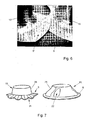
- wrinkle formation is understood to mean the formation of both primary wrinkles 21 in a flange 6 of the deep drawn product 15 and secondary wrinkles 22 in wall parts 25 of the product 15, as illustrated in Fig. 7 .
- the apparatus and method according to the invention are directed to suppressing both types of wrinkles.
- the apparatus 1 comprises a die 2 provided with a die opening 3 and a punch 4 arranged above this die opening 3.
- This punch 4 can be moved by means of suitable positioning means 7 into the opening 3, as shown in Fig. 1 on the right side.
- a blank 5 of starting material placed over the opening 3 is thereby forced into the opening 3 and deformed between the walls of this opening 3 and the punch 4 to a desired final product 15.
- the starting diameter Do of the blank 5 gradually decreases during this deep drawing, which is accompanied by an increase in the thickness d of the edge 6 and can further lead to wrinkle formation.
- a ring-shaped downholder 8 is arranged around the punch 4, which downholder can be moved with suitable positioning means 9 towards a die ring 10 extending around the die opening 3 while clamping the edge 6 of the blank 5.
- a downholder force F N exerted on the edge 6 by the downholder 8 will thereby increase according as the downholder opening S o, defined as the perpendicular distance between the downholder 8 and the die ring 10, increases.
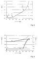
- the downholder force F N must remain between two extreme limits, a lower limit F N,min and an upper limit F N,max . These limits are graphically shown in Fig. 2 , as a function of the deep drawing ratio.
- the downholder force F N falls below the minimum limit F N , min , wrinkles will be formed in the product, while at exceeding the maximum limit F N,max cracks will be formed in the product 15.
- the downholder force F N is therefore adjusted to a 'safe' distance between both limits, so that a certain safety margin is present, in connection with possible spreading in the starting material (composition, thickness, etc.).
- the downholder force F N is contrarily exactly kept as close to the lower limit F N,min as possible.
- the risk of crack formation will thus be reduced to a minimum.
- this will also limit frictional forces F w occurring during deep drawing between the blank 5 and the downholder 8 and the die ring 10, since these frictional forces are proportional to the downholder force F N .
- Lower frictional forces ensure that less lubricant suffices, that the deep drawing process can take place under lower forces, with less work, and that the whole arrangement can be of lighter design.
- the downholder force F N is adjusted according to the invention to a low value and increased only if wrinkle formation occurs. Then the downholder force is increased to a value necessary to suppress the detected wrinkles. The downholder force F N will thus always be not greater than necessary to suppress the momentary wrinkle formation.
- the deep drawing apparatus 1 of Fig. 1 is therefore provided with measuring means 11, with which the mentioned downholder opening trend s o and/or downholder opening speed trend v o can be measured.
- These measuring means 11 may, for instance, comprise an optical, capacitive or magnetic sensor.
- the measuring means 11 are connected to a control 12, which is provided with means for comparing the measuring signals with a critical value or critical range adjusted for those signals, and which control 12 is further arranged to move, in case of exceeding the mentioned critical magnitudes, the downholder 8 towards the die 2 by means of the positioning means 9.
- These positioning means 9 may, for instance, comprise a piston-cylinder assembly, an electrically driven screw spindle, a piezo-electric element, or the like.
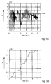
- the critical values can be determined during a testing measurement, by measuring, during this test, the downholder opening trend s o as shown in Fig. 3 . It is clearly visible that the downholder opening s o initially has a substantially constant value (range I-II) and then gradually increases at a constant inclination (range II-III) corresponding with a constant downholder opening speed v o . From point III, the measured downholder opening trend s o shows a bend, and this trend increases more rapidly, which indicates wrinkle formation P. On the basis of this measurement, therefore, the range I-III can be implemented in the control 12 as the sought critical downholder opening range. Instead thereof, bend point III may also be introduced as critical downholder opening value. When a downholder opening trend s o measured during deep drawing exceeds the critical range or the critical value, the thickness increase is greater than may be expected on the basis of the testing measurement, which indicates wrinkle formation.
- the deep drawing testing measurement may also be carried out at such a high downholder force F N that neither wrinkle formation, nor crack formation will occur.
- F N the thickness increase of the edge 6 of the blank 5.
- This measured downholder opening trend may therefore be implemented in the control 12 as critical range.
- the maximally measured thickness increase may also be introduced as critical value.
- the speed v o at which this downholder opening changes may also be measured during the mentioned testing measurement.
- This measured speed trend or a speed value measured to be highest during this measurement can be introduced into the control 12 as critical range or critical value for the downholder opening speed trend.
- the critical speed value can also be determined by the inclination of range II-III in Fig. 3 .
- Fig. 4 shows a measurement of the downholder opening s o and the downholder force F N over time, with the thinly drawn lines representing the trend without regulation according to the invention, while the thickly drawn lines represent the trend when the downholder force F N is controlled on the basis of the critical downholder opening determined in Fig. 3 . It is clearly visible that the downholder force F N is stepwise increased from the critical value determined in Fig. 3 (bend point III) and thus effectively suppresses (see thickly drawn s o line) wrinkle formation (see thinly drawn s o line).
- Fig. 4 further clearly shows that the downholder force initially begins relatively low and is increased only if this is actually necessary.
- the force may be increased stepwise, at a predetermined step size, or may be increased proportionally to the measured deviation. Also possible are other known per se regulation techniques, in which, for instance, use is made of integrating and/or differentiating actions.
- the apparatus may also be provided with a self-learning regulation, in which the step size of the force F N is initially adjusted by an operator, and the regulation itself adapts this value in the course of the process, on the basis of fed back measuring data.
- Fig. 5A,B is shown a simulation in which the downholder force is regulated on the basis of the measured opening speed v o and a critical speed value predetermined in the above-described manner, which, in the shown case, was approximately 1 x 10 -4 . It is clearly visible how the downholder force F N is increased stepwise, each time when the downholder opening speed exceeds the critical value. It is also visible that the increase of the downholder force F N is greater according as the exceeding of the critical value is greater.
- Fig. 6 shows, on the left side, a flange 6' of a product 15', manufactured with a conventional deep drawing method (see the thinly drawn lines in Fig. 4 ), while next to this, on the right side, a product 15 is shown, which has been manufactured with a method according to the invention (see the thickly drawn lines in Fig. 4 ). It clearly appears that the product according to the present method substantially has no wrinkles.
- not the downholder force is regulated on the basis of a measured beginning of wrinkle formation (feed-back regulation), but the position of the downholder and hence the downholder opening are regulated according to a predetermined range, such that the mentioned downholder opening corresponds with the thickness trend of the blank 5 to be expected (forward regulation).
- the thickness trend to be expected may be determined in the same manner as described before with reference to Fig. 3 .
- Such a forward regulation has the advantage that during the actual deep drawing no downholder opening or speed need be measured, so that a very simple apparatus, without measuring means and without advanced control, suffices.
- deep drawing may take place in one or more steps.
- the forward position regulation and feed-back force regulation may be combined, the force regulation being able to correctingly act on the position regulation.
Landscapes
- Engineering & Computer Science (AREA)
- Mechanical Engineering (AREA)
- Shaping Metal By Deep-Drawing, Or The Like (AREA)
- Details Of Garments (AREA)
- Bending Of Plates, Rods, And Pipes (AREA)
Claims (11)
- Verfahren zum Tiefziehen eines Produktes aus einer Platte, bei dem während des Tiefziehens die Platte nahe ihres Randes durch einen Niederhalter gegen einen Ziehring gehalten wird, der mit dem Niederhalter zusammenwirkt, wodurch durch Steuerung des Niederhalters die Bildung von Falten in der Platte verhindert oder wenigstens reduziert wird, dadurch gekennzeichnet, dass zu Beginn des Tiefziehens der Niederhalter (8) so eingestellt wird, dass eine Niederhaltekraft (FN), die durch den Niederhalter (8) auf den Rand (6) der Platte (5) ausgeübt wird, relativ klein ist, d.h. nicht größer als notwendig, um eine momentane Faltenbildung zu unterdrücken, und dass die weitere Steuerung des Niederhalters (3) auf Grundlage eines vorgegebenen Dickentrends des Randes (6) während des Tiefziehens und/oder eines Trends oder eines aus dem Dickentrend abgeleiteten kritischen Wertes erfolgt.
- Verfahren nach Anspruch 1, dadurch gekennzeichnet, dass während des Tiefziehens ein für die Faltenbildung relevanter Parameter gemessen und mit einem kritischen Wert verglichen wird, bei dem Faltenbildung auftritt, wobei der kritische Wert vorher bestimmt ist auf Grundlage des Dikkentrends des Plattenrandes (6) und/oder eines aus dem Dickentrend abgeleiteten Signals, und wobei, wenn der gemessene Parameter den kritischen Wert überschreitet oder diesen zu überschreiten droht, der Niederhalter (8) so gesteuert wird, dass die auf den Rand (6) durch den Niederhalter (8) ausgeübte Niedehaltekraft (FN) steigt und der gemessene Parameter unter den kritischen Wert fällt.
- Verfahren nach Anspruch 2, dadurch gekennzeichnet, dass der für die Faltenbildung relevante Parameter die Niederhalteröffnung (s0) ist, die als der senkrechte Abstand zwischen dem Niederhalter (8) und dem Ziehring (10) definiert ist, und dass der kritische Wert der vorgegebene Dickentrend oder der vorgegebene maximale Dickenanstieg des Randes (6) ist.
- Verfahren nach Anspruch 2, dadurch gekennzeichnet, dass der für die Faltenbildung relevante Parameter die Geschwindigkeit (v0) ist, mit der sich die Niederhalteröffnung ändert, und dass der kritische Wert der vorgegebene Geschwindigkeitstrend oder die vorgegebene maximale Geschwindigkeit ist, mit der der Plattenrand während des Tiefziehens in seiner Dicke anwächst.
- Verfahren nach einem der Ansprüche 2 - 4, dadurch gekennzeichnet, dass der kritische Wert während eines Testlaufs vor dem Tiefziehen gemessen wird.
- Verfahren nach einem der Ansprüche 2 - 4, dadurch gekennzeichnet, dass der kritische Wert mittels eines dynamischen Modells der Platte (5) und des Tiefziehvorgangs simuliert wird.
- Verfahren nach Anspruch 1, bei dem die Position des Niederhalters (8) gemäß einem vorgegebenen Bereich gesteuert wird, so dass während des Tiefziehens die Niederhalteröffnung (s0), definiert als der senkrechte Abstand zwischen dem Niederhalter (8) und dem Ziehring (10), im Wesentlichen einem vorgegebenen Dickentrend des Randes (6) entspricht, der während des Tiefziehens zu erwarten ist.
- Vorrichtung zum Tiefziehen eines Produkts aus einer Platte (5), mit einem Niederhalter (8), einem Ziehring (10), der damit zusammenwirkt, um einen Rand (6) der Platte während des Tiefziehens halten, einer Steuerung (12) und einer Positioniereinrichtung (9) zum Bewegen des Niederhalters (8), dadurch gekennzeichnet, dass die Steuerung (12) mit Einrichtungen zum Speichern eines gewünschten Niederhalteröffnungstrends (s0), eines Niederhalteröffnungsgeschwindigkeitstrends (v0) und/oder eines daraus abgeleiteten kritischen Wertes versehen ist und dazu ausgestaltet ist, um die Positioniereinrichtung (9) so zu steuern, dass die Bewegung des Niederhalters (8) mit dem gespeicherten Niederhalteröffnungstrend (s0), dem Niederhalteröffnungsgeschwindigkeitstrend (v0) und/oder einem daraus abgeleiteten kritischen Wert übereinstimmt.
- Vorrichtung nach Anspruch 8, bei dem die Steuerung (12) dazu ausgelegt ist, um die Positioniereinrichtung (9) so zu steuern, dass der Abstand zwischen dem Niederhalter (8) und dem Ziehring in Übereinstimmung mit dem gespeicherten Niederhalteröffnungstrend (so) oder einem daraus abgeleiteten kritischen Wert ist.
- Vorrichtung nach Anspruch 8 oder 9, bei der eine Messeinrichtung (11) vorgesehen ist, um den Niederhalteröffnungstrend (s0), den Niederhalteröffnungsgeschwindigkeitstrend (v0) und/oder einen daraus abgeleiteten kritischen Wert zu messen, und bei der die Steuerung (12) eine Einrichtung zum Vergleichen der mit der Messeinrichtung (11) gemessenen Signale mit einem Niederhalteröffnungstrend (s0), einem Niederhalteröffnungsgeschwindigkeitstrend (v0), die in der Steuerung (12) gespeichert sind, und/oder einem kritischen, daraus abgeleiteten Wert aufweist und bei der die Steuerung (12) dazu ausgelegt ist, den Niederhalter (8) auf Grundlage dessen so zu steuern, dass die Bewegung, die Geschwindigkeit oder der daraus abgeleitete kritische Wert des Niederhalters (8) in Übereinstimmung mit dem gespeicherten Niederhalteröffnungstrend, dem gespeicherten Niederhalteröffnungsgeschwindigkeitstrend und/oder dem gespeicherten, daraus abgeleiteten kritischen Wert ist.
- Vorrichtung nach einem der Ansprüche 8 - 10, dadurch gekennzeichnet, dass die Messeinrichtung (11) einen kontaktlosen Sensor umfasst, zum Beispiel einen optischen, kapazitiven oder magnetischen Sensor.
Applications Claiming Priority (3)
| Application Number | Priority Date | Filing Date | Title |
|---|---|---|---|
| NL1021738A NL1021738C2 (nl) | 2002-10-24 | 2002-10-24 | Werkwijze en inrichting voor het reduceren van plooivorming bij dieptrekken. |
| NL1021738 | 2002-10-24 | ||
| PCT/NL2003/000720 WO2004037460A1 (en) | 2002-10-24 | 2003-10-23 | Method and apparatus for reducing wrinkle formation in deep drawing |
Publications (2)
| Publication Number | Publication Date |
|---|---|
| EP1554067A1 EP1554067A1 (de) | 2005-07-20 |
| EP1554067B1 true EP1554067B1 (de) | 2008-09-17 |
Family
ID=32171726
Family Applications (1)
| Application Number | Title | Priority Date | Filing Date |
|---|---|---|---|
| EP03759078A Expired - Lifetime EP1554067B1 (de) | 2002-10-24 | 2003-10-23 | Verfahren und vorrichtung zum reduzieren von faltenbildung beim tiefziehen |
Country Status (7)
| Country | Link |
|---|---|
| US (1) | US20050268685A1 (de) |
| EP (1) | EP1554067B1 (de) |
| AT (1) | ATE408465T1 (de) |
| AU (1) | AU2003275734A1 (de) |
| DE (1) | DE60323658D1 (de) |
| NL (1) | NL1021738C2 (de) |
| WO (1) | WO2004037460A1 (de) |
Families Citing this family (6)
| Publication number | Priority date | Publication date | Assignee | Title |
|---|---|---|---|---|
| JP6075304B2 (ja) * | 2013-03-28 | 2017-02-08 | 株式会社豊田中央研究所 | 熱間プレス成形方法および熱間プレス成形装置 |
| JP6265196B2 (ja) * | 2015-11-06 | 2018-01-24 | 株式会社山王 | シート状被検物のしなやかさの評価方法及び評価装置 |
| DE102016118418A1 (de) | 2016-09-29 | 2018-03-29 | Thyssenkrupp Ag | Verfahren zur Herstellung eines geformten Bauteils mit einem maßhaltigen Zargenbereich |
| JP6835023B2 (ja) * | 2018-03-26 | 2021-02-24 | Jfeスチール株式会社 | 高張力鋼板の遅れ破壊特性評価方法 |
| CN114535392B (zh) * | 2022-02-14 | 2024-05-03 | 一汽解放汽车有限公司 | 拉延模具的拉延筋的制作方法及拉延模具 |
| US11833567B2 (en) * | 2022-04-26 | 2023-12-05 | GM Global Technology Operations LLC | Die adjustment systems and methods with draw in sensors |
Family Cites Families (9)
| Publication number | Priority date | Publication date | Assignee | Title |
|---|---|---|---|---|
| CH576297A5 (de) * | 1974-06-11 | 1976-06-15 | Luwa Ag | |
| US4316379A (en) * | 1978-09-12 | 1982-02-23 | Mts Systems Corporation | Deep drawing press with blanking and draw pad pressure control |
| JPS56500008A (de) * | 1978-12-21 | 1981-01-08 | ||
| DE3735582C1 (de) * | 1987-10-21 | 1988-04-28 | Daimler Benz Ag | Doppeltwirkende Presse zum Ziehen von Blechteilen |
| DD289724A5 (de) * | 1989-12-05 | 1991-05-08 | Fz Fuer Umform- Und Plastverarbeitungstechnik,De | Verfahren zur erhoehung des grenztiefziehverhaeltnisses |
| BE1004564A3 (fr) * | 1990-08-30 | 1992-12-15 | Cockerill Rech & Dev | Dispositif de regulation de la force de serre-flan dans une presse. |
| DE4434419A1 (de) * | 1994-09-26 | 1996-03-28 | Mueller Weingarten Maschf | Mechanische und hydraulische Pressen |
| DE19718841A1 (de) * | 1996-05-06 | 1997-11-13 | Mueller Weingarten Maschf | Verfahren zur Materialflußsteuerung beim Ziehen von Blechformteilen sowie Vorrichtung zur Durchführung des Verfahrens |
| WO2002090875A2 (en) * | 2001-05-07 | 2002-11-14 | Northwestern University | Real-time draw-in sensors and methods of fabrication |
-
2002
- 2002-10-24 NL NL1021738A patent/NL1021738C2/nl not_active IP Right Cessation
-
2003
- 2003-10-23 AT AT03759078T patent/ATE408465T1/de not_active IP Right Cessation
- 2003-10-23 DE DE60323658T patent/DE60323658D1/de not_active Expired - Lifetime
- 2003-10-23 US US10/532,360 patent/US20050268685A1/en not_active Abandoned
- 2003-10-23 EP EP03759078A patent/EP1554067B1/de not_active Expired - Lifetime
- 2003-10-23 WO PCT/NL2003/000720 patent/WO2004037460A1/en not_active Ceased
- 2003-10-23 AU AU2003275734A patent/AU2003275734A1/en not_active Abandoned
Also Published As
| Publication number | Publication date |
|---|---|
| ATE408465T1 (de) | 2008-10-15 |
| DE60323658D1 (de) | 2008-10-30 |
| NL1021738C2 (nl) | 2004-04-27 |
| EP1554067A1 (de) | 2005-07-20 |
| US20050268685A1 (en) | 2005-12-08 |
| WO2004037460A1 (en) | 2004-05-06 |
| AU2003275734A1 (en) | 2004-05-13 |
Similar Documents
| Publication | Publication Date | Title |
|---|---|---|
| DE69121109T2 (de) | Gesenkpolstereinrichtung für presse | |
| US11980966B2 (en) | Method, computer program and laser cutting system for smart corner cutting | |
| JP3574218B2 (ja) | 摩擦摩耗試験法及び試験機 | |
| EP1554067B1 (de) | Verfahren und vorrichtung zum reduzieren von faltenbildung beim tiefziehen | |
| Min et al. | Acoustic emission based tool contact detection for ultra-precision machining | |
| JPH0227114B2 (de) | ||
| WO2013007674A1 (de) | Verfahren zum bearbeiten eines werkstücks und bearbeitungsvorrichtung | |
| EP0401847A3 (de) | Verfahren und Einrichtung zum Steuern einer Brennkraftmaschine während einer Prüfung des Motorkennlinienverlaufs | |
| JP2018202464A (ja) | プレス機械のダブルブランク検出装置及びプレス機械の金型保護装置 | |
| JP2015057293A (ja) | ワークピースの精密打抜き時及び/又は変形加工時の工具の破断の防止のための装置及び方法 | |
| US20130067977A1 (en) | Tool unit of a rotary swaging machine | |
| US20190232389A1 (en) | Method and device for monitoring a tool clamping system of a work spindle of a numerically controlled machine tool | |
| KR102274047B1 (ko) | 전원 차단이나 비상정지 시 수직축에 부설된 스핀들헤드의 인상 량 자동 조정방법 | |
| US8006538B2 (en) | Control device for servo die cushion | |
| JPWO2023223470A5 (ja) | 制御パラメータ調整装置 | |
| JP2693664B2 (ja) | エンドミル加工における加工状態判定装置 | |
| JP2010253540A (ja) | ダイクッション装置とそのクッション力制御方法 | |
| US4963302A (en) | Method and apparatus for quality control of molded articles manufactured by injection molding machines or die casting machines | |
| US10843361B2 (en) | Control of a metal-cutting machining process by means of p-controller and a load-dependent control factor based on a control deviation e(t) between a control quantity y(t) and a guide quantity w(t) | |
| JPS63180400A (ja) | プレス機の自動荷重制御装置 | |
| JP2011502804A (ja) | 接続部品、多軸複合工作機械および弾性制御方法 | |
| US20090072499A1 (en) | System for centrifugal-force compensation in a hydraulic machining-chuck actuator | |
| JP5440838B2 (ja) | 油圧ダイクッション装置とその位置制御方法 | |
| JPS59101232A (ja) | 折曲げ機の曲げ角度検出制御装置 | |
| JPH049216A (ja) | 折曲げ加工方法及び装置 |
Legal Events
| Date | Code | Title | Description |
|---|---|---|---|
| PUAI | Public reference made under article 153(3) epc to a published international application that has entered the european phase |
Free format text: ORIGINAL CODE: 0009012 |
|
| 17P | Request for examination filed |
Effective date: 20050425 |
|
| AK | Designated contracting states |
Kind code of ref document: A1 Designated state(s): AT BE BG CH CY CZ DE DK EE ES FI FR GB GR HU IE IT LI LU MC NL PT RO SE SI SK TR |
|
| AX | Request for extension of the european patent |
Extension state: AL LT LV MK |
|
| DAX | Request for extension of the european patent (deleted) | ||
| 17Q | First examination report despatched |
Effective date: 20070122 |
|
| GRAP | Despatch of communication of intention to grant a patent |
Free format text: ORIGINAL CODE: EPIDOSNIGR1 |
|
| GRAS | Grant fee paid |
Free format text: ORIGINAL CODE: EPIDOSNIGR3 |
|
| GRAA | (expected) grant |
Free format text: ORIGINAL CODE: 0009210 |
|
| AK | Designated contracting states |
Kind code of ref document: B1 Designated state(s): AT BE BG CH CY CZ DE DK EE ES FI FR GB GR HU IE IT LI LU MC NL PT RO SE SI SK TR |
|
| REG | Reference to a national code |
Ref country code: GB Ref legal event code: FG4D |
|
| REG | Reference to a national code |
Ref country code: CH Ref legal event code: EP |
|
| REG | Reference to a national code |
Ref country code: IE Ref legal event code: FG4D |
|
| REF | Corresponds to: |
Ref document number: 60323658 Country of ref document: DE Date of ref document: 20081030 Kind code of ref document: P |
|
| PG25 | Lapsed in a contracting state [announced via postgrant information from national office to epo] |
Ref country code: FI Free format text: LAPSE BECAUSE OF FAILURE TO SUBMIT A TRANSLATION OF THE DESCRIPTION OR TO PAY THE FEE WITHIN THE PRESCRIBED TIME-LIMIT Effective date: 20080917 Ref country code: AT Free format text: LAPSE BECAUSE OF FAILURE TO SUBMIT A TRANSLATION OF THE DESCRIPTION OR TO PAY THE FEE WITHIN THE PRESCRIBED TIME-LIMIT Effective date: 20080917 Ref country code: SI Free format text: LAPSE BECAUSE OF FAILURE TO SUBMIT A TRANSLATION OF THE DESCRIPTION OR TO PAY THE FEE WITHIN THE PRESCRIBED TIME-LIMIT Effective date: 20080917 |
|
| PG25 | Lapsed in a contracting state [announced via postgrant information from national office to epo] |
Ref country code: ES Free format text: LAPSE BECAUSE OF FAILURE TO SUBMIT A TRANSLATION OF THE DESCRIPTION OR TO PAY THE FEE WITHIN THE PRESCRIBED TIME-LIMIT Effective date: 20081228 Ref country code: BG Free format text: LAPSE BECAUSE OF FAILURE TO SUBMIT A TRANSLATION OF THE DESCRIPTION OR TO PAY THE FEE WITHIN THE PRESCRIBED TIME-LIMIT Effective date: 20081217 |
|
| PG25 | Lapsed in a contracting state [announced via postgrant information from national office to epo] |
Ref country code: MC Free format text: LAPSE BECAUSE OF NON-PAYMENT OF DUE FEES Effective date: 20081031 Ref country code: PT Free format text: LAPSE BECAUSE OF FAILURE TO SUBMIT A TRANSLATION OF THE DESCRIPTION OR TO PAY THE FEE WITHIN THE PRESCRIBED TIME-LIMIT Effective date: 20090217 Ref country code: SK Free format text: LAPSE BECAUSE OF FAILURE TO SUBMIT A TRANSLATION OF THE DESCRIPTION OR TO PAY THE FEE WITHIN THE PRESCRIBED TIME-LIMIT Effective date: 20080917 Ref country code: CZ Free format text: LAPSE BECAUSE OF FAILURE TO SUBMIT A TRANSLATION OF THE DESCRIPTION OR TO PAY THE FEE WITHIN THE PRESCRIBED TIME-LIMIT Effective date: 20080917 Ref country code: RO Free format text: LAPSE BECAUSE OF FAILURE TO SUBMIT A TRANSLATION OF THE DESCRIPTION OR TO PAY THE FEE WITHIN THE PRESCRIBED TIME-LIMIT Effective date: 20080917 |
|
| REG | Reference to a national code |
Ref country code: CH Ref legal event code: PL |
|
| REG | Reference to a national code |
Ref country code: IE Ref legal event code: MM4A |
|
| PLBE | No opposition filed within time limit |
Free format text: ORIGINAL CODE: 0009261 |
|
| STAA | Information on the status of an ep patent application or granted ep patent |
Free format text: STATUS: NO OPPOSITION FILED WITHIN TIME LIMIT |
|
| PG25 | Lapsed in a contracting state [announced via postgrant information from national office to epo] |
Ref country code: EE Free format text: LAPSE BECAUSE OF FAILURE TO SUBMIT A TRANSLATION OF THE DESCRIPTION OR TO PAY THE FEE WITHIN THE PRESCRIBED TIME-LIMIT Effective date: 20080917 Ref country code: DK Free format text: LAPSE BECAUSE OF FAILURE TO SUBMIT A TRANSLATION OF THE DESCRIPTION OR TO PAY THE FEE WITHIN THE PRESCRIBED TIME-LIMIT Effective date: 20080917 |
|
| 26N | No opposition filed |
Effective date: 20090618 |
|
| PG25 | Lapsed in a contracting state [announced via postgrant information from national office to epo] |
Ref country code: CH Free format text: LAPSE BECAUSE OF NON-PAYMENT OF DUE FEES Effective date: 20081031 Ref country code: IE Free format text: LAPSE BECAUSE OF NON-PAYMENT OF DUE FEES Effective date: 20081023 Ref country code: LI Free format text: LAPSE BECAUSE OF NON-PAYMENT OF DUE FEES Effective date: 20081031 |
|
| PG25 | Lapsed in a contracting state [announced via postgrant information from national office to epo] |
Ref country code: SE Free format text: LAPSE BECAUSE OF FAILURE TO SUBMIT A TRANSLATION OF THE DESCRIPTION OR TO PAY THE FEE WITHIN THE PRESCRIBED TIME-LIMIT Effective date: 20081217 |
|
| PG25 | Lapsed in a contracting state [announced via postgrant information from national office to epo] |
Ref country code: LU Free format text: LAPSE BECAUSE OF NON-PAYMENT OF DUE FEES Effective date: 20081023 Ref country code: HU Free format text: LAPSE BECAUSE OF FAILURE TO SUBMIT A TRANSLATION OF THE DESCRIPTION OR TO PAY THE FEE WITHIN THE PRESCRIBED TIME-LIMIT Effective date: 20090318 Ref country code: CY Free format text: LAPSE BECAUSE OF FAILURE TO SUBMIT A TRANSLATION OF THE DESCRIPTION OR TO PAY THE FEE WITHIN THE PRESCRIBED TIME-LIMIT Effective date: 20080917 |
|
| PG25 | Lapsed in a contracting state [announced via postgrant information from national office to epo] |
Ref country code: TR Free format text: LAPSE BECAUSE OF FAILURE TO SUBMIT A TRANSLATION OF THE DESCRIPTION OR TO PAY THE FEE WITHIN THE PRESCRIBED TIME-LIMIT Effective date: 20080917 |
|
| PG25 | Lapsed in a contracting state [announced via postgrant information from national office to epo] |
Ref country code: GR Free format text: LAPSE BECAUSE OF FAILURE TO SUBMIT A TRANSLATION OF THE DESCRIPTION OR TO PAY THE FEE WITHIN THE PRESCRIBED TIME-LIMIT Effective date: 20081218 |
|
| PGFP | Annual fee paid to national office [announced via postgrant information from national office to epo] |
Ref country code: BE Payment date: 20131022 Year of fee payment: 11 Ref country code: GB Payment date: 20131021 Year of fee payment: 11 Ref country code: FR Payment date: 20131022 Year of fee payment: 11 Ref country code: DE Payment date: 20131021 Year of fee payment: 11 |
|
| PGFP | Annual fee paid to national office [announced via postgrant information from national office to epo] |
Ref country code: IT Payment date: 20131028 Year of fee payment: 11 Ref country code: NL Payment date: 20131022 Year of fee payment: 11 |
|
| REG | Reference to a national code |
Ref country code: DE Ref legal event code: R119 Ref document number: 60323658 Country of ref document: DE |
|
| REG | Reference to a national code |
Ref country code: NL Ref legal event code: V1 Effective date: 20150501 |
|
| GBPC | Gb: european patent ceased through non-payment of renewal fee |
Effective date: 20141023 |
|
| PG25 | Lapsed in a contracting state [announced via postgrant information from national office to epo] |
Ref country code: BE Free format text: LAPSE BECAUSE OF NON-PAYMENT OF DUE FEES Effective date: 20141031 |
|
| PG25 | Lapsed in a contracting state [announced via postgrant information from national office to epo] |
Ref country code: GB Free format text: LAPSE BECAUSE OF NON-PAYMENT OF DUE FEES Effective date: 20141023 Ref country code: DE Free format text: LAPSE BECAUSE OF NON-PAYMENT OF DUE FEES Effective date: 20150501 |
|
| REG | Reference to a national code |
Ref country code: FR Ref legal event code: ST Effective date: 20150630 |
|
| PG25 | Lapsed in a contracting state [announced via postgrant information from national office to epo] |
Ref country code: IT Free format text: LAPSE BECAUSE OF NON-PAYMENT OF DUE FEES Effective date: 20141023 Ref country code: FR Free format text: LAPSE BECAUSE OF NON-PAYMENT OF DUE FEES Effective date: 20141031 Ref country code: NL Free format text: LAPSE BECAUSE OF NON-PAYMENT OF DUE FEES Effective date: 20150501 |