EP1554080B1 - Dispositif porte-outil et procede pour positionner un outil - Google Patents
Dispositif porte-outil et procede pour positionner un outil Download PDFInfo
- Publication number
- EP1554080B1 EP1554080B1 EP03758023A EP03758023A EP1554080B1 EP 1554080 B1 EP1554080 B1 EP 1554080B1 EP 03758023 A EP03758023 A EP 03758023A EP 03758023 A EP03758023 A EP 03758023A EP 1554080 B1 EP1554080 B1 EP 1554080B1
- Authority
- EP
- European Patent Office
- Prior art keywords
- tool
- chuck
- holding device
- positioning means
- holding
- Prior art date
- Legal status (The legal status is an assumption and is not a legal conclusion. Google has not performed a legal analysis and makes no representation as to the accuracy of the status listed.)
- Expired - Lifetime
Links
- 238000000034 method Methods 0.000 title claims description 20
- 238000010438 heat treatment Methods 0.000 claims description 7
- 230000003287 optical effect Effects 0.000 claims description 7
- 230000006698 induction Effects 0.000 claims description 6
- 230000005489 elastic deformation Effects 0.000 claims description 3
- 238000005096 rolling process Methods 0.000 description 12
- 238000005259 measurement Methods 0.000 description 10
- 238000011156 evaluation Methods 0.000 description 8
- 238000003780 insertion Methods 0.000 description 4
- 230000037431 insertion Effects 0.000 description 4
- 238000001816 cooling Methods 0.000 description 3
- 238000013461 design Methods 0.000 description 3
- 238000003754 machining Methods 0.000 description 3
- 230000004323 axial length Effects 0.000 description 2
- 229910000831 Steel Inorganic materials 0.000 description 1
- 238000012937 correction Methods 0.000 description 1
- 239000013013 elastic material Substances 0.000 description 1
- 238000007373 indentation Methods 0.000 description 1
- 238000005070 sampling Methods 0.000 description 1
- 238000000926 separation method Methods 0.000 description 1
- 239000010959 steel Substances 0.000 description 1
Images


Classifications
-
- B—PERFORMING OPERATIONS; TRANSPORTING
- B23—MACHINE TOOLS; METAL-WORKING NOT OTHERWISE PROVIDED FOR
- B23B—TURNING; BORING
- B23B31/00—Chucks; Expansion mandrels; Adaptations thereof for remote control
- B23B31/02—Chucks
- B23B31/028—Chucks the axial positioning of the tool being adjustable
-
- B—PERFORMING OPERATIONS; TRANSPORTING
- B23—MACHINE TOOLS; METAL-WORKING NOT OTHERWISE PROVIDED FOR
- B23B—TURNING; BORING
- B23B31/00—Chucks; Expansion mandrels; Adaptations thereof for remote control
- B23B31/02—Chucks
- B23B31/10—Chucks characterised by the retaining or gripping devices or their immediate operating means
- B23B31/117—Retention by friction only, e.g. using springs, resilient sleeves, tapers
- B23B31/1179—Retention by friction only, e.g. using springs, resilient sleeves, tapers using heating and cooling
-
- B—PERFORMING OPERATIONS; TRANSPORTING
- B23—MACHINE TOOLS; METAL-WORKING NOT OTHERWISE PROVIDED FOR
- B23P—METAL-WORKING NOT OTHERWISE PROVIDED FOR; COMBINED OPERATIONS; UNIVERSAL MACHINE TOOLS
- B23P11/00—Connecting or disconnecting metal parts or objects by metal-working techniques not otherwise provided for
- B23P11/02—Connecting or disconnecting metal parts or objects by metal-working techniques not otherwise provided for by first expanding and then shrinking or vice versa, e.g. by using pressure fluids; by making force fits
- B23P11/025—Connecting or disconnecting metal parts or objects by metal-working techniques not otherwise provided for by first expanding and then shrinking or vice versa, e.g. by using pressure fluids; by making force fits by using heat or cold
- B23P11/027—Connecting or disconnecting metal parts or objects by metal-working techniques not otherwise provided for by first expanding and then shrinking or vice versa, e.g. by using pressure fluids; by making force fits by using heat or cold for mounting tools in tool holders
-
- B—PERFORMING OPERATIONS; TRANSPORTING
- B23—MACHINE TOOLS; METAL-WORKING NOT OTHERWISE PROVIDED FOR
- B23B—TURNING; BORING
- B23B2260/00—Details of constructional elements
- B23B2260/026—Bushings, e.g. adapter sleeves
-
- Y—GENERAL TAGGING OF NEW TECHNOLOGICAL DEVELOPMENTS; GENERAL TAGGING OF CROSS-SECTIONAL TECHNOLOGIES SPANNING OVER SEVERAL SECTIONS OF THE IPC; TECHNICAL SUBJECTS COVERED BY FORMER USPC CROSS-REFERENCE ART COLLECTIONS [XRACs] AND DIGESTS
- Y10—TECHNICAL SUBJECTS COVERED BY FORMER USPC
- Y10T—TECHNICAL SUBJECTS COVERED BY FORMER US CLASSIFICATION
- Y10T279/00—Chucks or sockets
- Y10T279/12—Chucks or sockets with fluid-pressure actuator
- Y10T279/1216—Jaw is expansible chamber; i.e., bladder type
-
- Y—GENERAL TAGGING OF NEW TECHNOLOGICAL DEVELOPMENTS; GENERAL TAGGING OF CROSS-SECTIONAL TECHNOLOGIES SPANNING OVER SEVERAL SECTIONS OF THE IPC; TECHNICAL SUBJECTS COVERED BY FORMER USPC CROSS-REFERENCE ART COLLECTIONS [XRACs] AND DIGESTS
- Y10—TECHNICAL SUBJECTS COVERED BY FORMER USPC
- Y10T—TECHNICAL SUBJECTS COVERED BY FORMER US CLASSIFICATION
- Y10T279/00—Chucks or sockets
- Y10T279/17—Socket type
- Y10T279/17957—Friction grip
-
- Y—GENERAL TAGGING OF NEW TECHNOLOGICAL DEVELOPMENTS; GENERAL TAGGING OF CROSS-SECTIONAL TECHNOLOGIES SPANNING OVER SEVERAL SECTIONS OF THE IPC; TECHNICAL SUBJECTS COVERED BY FORMER USPC CROSS-REFERENCE ART COLLECTIONS [XRACs] AND DIGESTS
- Y10—TECHNICAL SUBJECTS COVERED BY FORMER USPC
- Y10T—TECHNICAL SUBJECTS COVERED BY FORMER US CLASSIFICATION
- Y10T279/00—Chucks or sockets
- Y10T279/34—Accessory or component
- Y10T279/3487—Tool or work stop or locator
-
- Y—GENERAL TAGGING OF NEW TECHNOLOGICAL DEVELOPMENTS; GENERAL TAGGING OF CROSS-SECTIONAL TECHNOLOGIES SPANNING OVER SEVERAL SECTIONS OF THE IPC; TECHNICAL SUBJECTS COVERED BY FORMER USPC CROSS-REFERENCE ART COLLECTIONS [XRACs] AND DIGESTS
- Y10—TECHNICAL SUBJECTS COVERED BY FORMER USPC
- Y10T—TECHNICAL SUBJECTS COVERED BY FORMER US CLASSIFICATION
- Y10T29/00—Metal working
- Y10T29/49—Method of mechanical manufacture
- Y10T29/49764—Method of mechanical manufacture with testing or indicating
- Y10T29/49769—Using optical instrument [excludes mere human eyeballing]
-
- Y—GENERAL TAGGING OF NEW TECHNOLOGICAL DEVELOPMENTS; GENERAL TAGGING OF CROSS-SECTIONAL TECHNOLOGIES SPANNING OVER SEVERAL SECTIONS OF THE IPC; TECHNICAL SUBJECTS COVERED BY FORMER USPC CROSS-REFERENCE ART COLLECTIONS [XRACs] AND DIGESTS
- Y10—TECHNICAL SUBJECTS COVERED BY FORMER USPC
- Y10T—TECHNICAL SUBJECTS COVERED BY FORMER US CLASSIFICATION
- Y10T29/00—Metal working
- Y10T29/49—Method of mechanical manufacture
- Y10T29/49764—Method of mechanical manufacture with testing or indicating
- Y10T29/49778—Method of mechanical manufacture with testing or indicating with aligning, guiding, or instruction
- Y10T29/4978—Assisting assembly or disassembly
-
- Y—GENERAL TAGGING OF NEW TECHNOLOGICAL DEVELOPMENTS; GENERAL TAGGING OF CROSS-SECTIONAL TECHNOLOGIES SPANNING OVER SEVERAL SECTIONS OF THE IPC; TECHNICAL SUBJECTS COVERED BY FORMER USPC CROSS-REFERENCE ART COLLECTIONS [XRACs] AND DIGESTS
- Y10—TECHNICAL SUBJECTS COVERED BY FORMER USPC
- Y10T—TECHNICAL SUBJECTS COVERED BY FORMER US CLASSIFICATION
- Y10T29/00—Metal working
- Y10T29/49—Method of mechanical manufacture
- Y10T29/49826—Assembling or joining
- Y10T29/49863—Assembling or joining with prestressing of part
- Y10T29/49865—Assembling or joining with prestressing of part by temperature differential [e.g., shrink fit]
-
- Y—GENERAL TAGGING OF NEW TECHNOLOGICAL DEVELOPMENTS; GENERAL TAGGING OF CROSS-SECTIONAL TECHNOLOGIES SPANNING OVER SEVERAL SECTIONS OF THE IPC; TECHNICAL SUBJECTS COVERED BY FORMER USPC CROSS-REFERENCE ART COLLECTIONS [XRACs] AND DIGESTS
- Y10—TECHNICAL SUBJECTS COVERED BY FORMER USPC
- Y10T—TECHNICAL SUBJECTS COVERED BY FORMER US CLASSIFICATION
- Y10T408/00—Cutting by use of rotating axially moving tool
- Y10T408/83—Tool-support with means to move Tool relative to tool-support
- Y10T408/85—Tool-support with means to move Tool relative to tool-support to move radially
- Y10T408/858—Moving means including wedge, screw or cam
- Y10T408/8583—Moving means including wedge, screw or cam with resiliently urged Tool
- Y10T408/85843—Resilient Tool or tool-support
-
- Y—GENERAL TAGGING OF NEW TECHNOLOGICAL DEVELOPMENTS; GENERAL TAGGING OF CROSS-SECTIONAL TECHNOLOGIES SPANNING OVER SEVERAL SECTIONS OF THE IPC; TECHNICAL SUBJECTS COVERED BY FORMER USPC CROSS-REFERENCE ART COLLECTIONS [XRACs] AND DIGESTS
- Y10—TECHNICAL SUBJECTS COVERED BY FORMER USPC
- Y10T—TECHNICAL SUBJECTS COVERED BY FORMER US CLASSIFICATION
- Y10T409/00—Gear cutting, milling, or planing
- Y10T409/30—Milling
- Y10T409/308624—Milling with limit means to aid in positioning of cutter bit or work [e.g., gauge, stop, etc.]
-
- Y—GENERAL TAGGING OF NEW TECHNOLOGICAL DEVELOPMENTS; GENERAL TAGGING OF CROSS-SECTIONAL TECHNOLOGIES SPANNING OVER SEVERAL SECTIONS OF THE IPC; TECHNICAL SUBJECTS COVERED BY FORMER USPC CROSS-REFERENCE ART COLLECTIONS [XRACs] AND DIGESTS
- Y10—TECHNICAL SUBJECTS COVERED BY FORMER USPC
- Y10T—TECHNICAL SUBJECTS COVERED BY FORMER US CLASSIFICATION
- Y10T409/00—Gear cutting, milling, or planing
- Y10T409/30—Milling
- Y10T409/30952—Milling with cutter holder
Definitions
- a movably mounted holding element is arranged in the tool receiving area. Due to the movable mounting of the holding element, a tool can be introduced into the tool receiving area, which is designed, for example, as a tool receiving opening, in a particularly simple manner, and sliding friction during insertion of the tool can be at least largely avoided.
- the movably mounted holding element is arranged in the connection region, which is advantageous with regard to the mounting of the connection region on the tool chuck.
- the movably mounted holding element may be a rolling element, in particular a ball or a rolling element cage, in particular a ball cage.
Landscapes
- Engineering & Computer Science (AREA)
- Mechanical Engineering (AREA)
- Machine Tool Sensing Apparatuses (AREA)
- Gripping On Spindles (AREA)
- Automatic Tool Replacement In Machine Tools (AREA)
Claims (16)
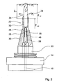
- Dispositif doté d'un outil (24), d'un mandrin (20) à outil et d'un dispositif (22, 50, 58) qui maintient l'outil (24) dans le mandrin (20) à outil avant un échauffement d'une zone (30) de réception d'outil du mandrin (20) d'outil et avant une fixation de l'outil (24) dans le mandrin (20) d'outil par un processus de rétrécissement, ledit dispositif présentant une zone (32, 52, 66) de réception d'outil qui reçoit au moins une partie de l'outil (24), une zone de liaison (26, 54, 62) destinée à être placée sur le mandrin (20) à outil et une ouverture de positionnement (48) par laquelle un moyen de positionnement (18) peut être placé sur l'outil (24) disposé au moins en partie dans la zone (32, 52, 66) de réception d'outil.
- Dispositif (22, 50, 58) de maintien d'outil selon la revendication 1, caractérisé en ce que la zone (32, 52, 66) de réception d'outil est prévue pour maintenir l'outil (24) aligné sur une ouverture de réception (28) du mandrin (20) à outil lorsque le mandrin (20) à outil est disposé dans la zone de liaison (26, 54, 62).
- Dispositif (22, 50) de maintien d'outil selon les revendications 1 ou 2, caractérisé en ce que la zone de liaison (26, 54) présente une tige destinée à être disposée dans une ouverture de réception (28) du mandrin (20) à outil.
- Dispositif (50, 58) de maintien d'outil selon l'une des revendications précédentes, caractérisé en ce qu'un élément de maintien (56, 68) prévu pour se déformer élastiquement est disposé dans la zone de liaison (54, 62) et/ou dans la zone (52, 66) de réception d'outil.
- Dispositif (50) de maintien d'outil selon la revendication 4, caractérisé en ce que l'élément de maintien (56) présente un joint torique.
- Dispositif (58) de maintien d'outil selon l'une des revendications précédentes, caractérisé en ce qu'un élément de maintien (68) monté à déplacement est disposé dans la zone de liaison (62) et/ou dans la zone (66) de réception d'outil.
- Dispositif (58) de maintien d'outil selon les revendications 4 ou 6, caractérisé en ce que l'élément de maintien (68) est une cage pour corps de roulement.
- Dispositif (58) de maintien d'outil selon l'une des revendications précédentes, caractérisé en ce que la zone de liaison (62) présente une paroi intérieure (64) destinée à être placée autour d'une paroi extérieure (60) du mandrin (20) à outil.
- Dispositif (50) de maintien d'outil selon la revendication 8, caractérisé en ce que la paroi intérieure (64) est conique.
- Procédé de positionnement d'un outil (24) dans un mandrin (20) à outil, dans lequel un dispositif (22, 50, 58) de maintien d'outil est disposé sur le mandrin (20) à outil avant un échauffement d'une zone (30) de réception d'outil du mandrin (20) d'outil et avant une fixation de l'outil (24) dans le mandrin (20) d'outil par un processus de rétrécissement, l'outil (24) étant maintenu par le dispositif (22, 50, 58) de maintien d'outil, un élément caractéristique (42) de l'outil (24) étant relevé pour positionner un moyen de positionnement (18), le moyen de positionnement (18) appliquant sur l'outil (24) une force à travers une ouverture de positionnement (48) ménagée dans le dispositif (22, 50, 58) de maintien d'outil, l'outil (24) étant ensuite retiré du dispositif (22) de maintien d'outil et le dispositif (22) de maintien d'outil étant retiré du mandrin (20) à outil et le chauffage de la zone de réception (30) du mandrin (20) à outil et donc le processus de fixation de l'outil (24) par rétré-cissement étant lancés en insérant manuellement ou automatiquement une bobine d'induction (12).
- Procédé selon la revendication 10, caractérisé en ce que la force appliquée sur l'outil (24) est maintenue pendant la mesure de l'élément caractéristique (42).
- Procédé selon les revendications 10 ou 11, caractérisé en ce que le moyen de positionnement (18) est placé sur l'outil (24) avant la mesure de l'élément caractéristique (42), l'outil (24) étant examiné lors du placement.
- Procédé selon la revendication 12, caractérisé en ce que le placement du moyen de positionnement (18) entraîne un déplacement de l'outil (24), le déplacement étant utilisé comme déclencheur d'arrêt du déplacement du moyen de positionnement (18).
- Procédé selon l'une des revendications 10 à 13, caractérisé en ce qu'avant la mesure de l'élément caractéristique (42), l'outil (24) est relevé dans le dispositif (22, 50, 58) de maintien d'outil par le moyen de positionnement (18) et est maintenu relevé pendant la mesure.
- Procédé selon l'une des revendications 10 à 14, caractérisé en ce qu'une optique de mesure (6) est focalisée sur un point prédéterminé, en ce qu'en cas d'absence d'un outil (24) dans le champ de vision (36, 36a) de l'optique de mesure (6), l'optique de mesure (6) est approchée du mandrin (20) à outil dans la direction axiale (40) d'une zone (32, 52, 66) de réception d'outil du dispositif (22, 50, 58) de maintien d'outil, en ce que, lorsque l'outil (24) est visible dans le champ de vision (36, 36a), l'optique de mesure (6) est enlevée du mandrin (20) à outil dans la direction axiale (40) d'une zone (32, 52, 66) de réception d'outil du dispositif (22, 50, 58) de maintien d'outil, la position effective (Zist) de l'élément caractéristique (42) étant déterminée lors de son apparition dans le champ de vision (36, 36a), la force étant ensuite appliquée sur l'outil (24).
- Procédé selon la revendication 15, caractérisé en ce qu'après l'application de la force, la position effective (Zist) est mesurée à nouveau pour déterminer la position de consigne du moyen de positionnement (18).
Priority Applications (1)
| Application Number | Priority Date | Filing Date | Title |
|---|---|---|---|
| DE20321113U DE20321113U1 (de) | 2002-12-11 | 2003-10-20 | Werkzeughaltevorrichtung |
Applications Claiming Priority (3)
| Application Number | Priority Date | Filing Date | Title |
|---|---|---|---|
| DE10258055 | 2002-12-11 | ||
| DE10258055 | 2002-12-11 | ||
| PCT/EP2003/011592 WO2004052591A1 (fr) | 2002-12-11 | 2003-10-20 | Dispositif porte-outil et procédé pour positionner un outil |
Publications (2)
| Publication Number | Publication Date |
|---|---|
| EP1554080A1 EP1554080A1 (fr) | 2005-07-20 |
| EP1554080B1 true EP1554080B1 (fr) | 2008-08-13 |
Family
ID=32403796
Family Applications (1)
| Application Number | Title | Priority Date | Filing Date |
|---|---|---|---|
| EP03758023A Expired - Lifetime EP1554080B1 (fr) | 2002-12-11 | 2003-10-20 | Dispositif porte-outil et procede pour positionner un outil |
Country Status (6)
| Country | Link |
|---|---|
| US (2) | US7371036B2 (fr) |
| EP (1) | EP1554080B1 (fr) |
| AT (1) | ATE404322T1 (fr) |
| AU (1) | AU2003274045A1 (fr) |
| DE (3) | DE20321113U1 (fr) |
| WO (1) | WO2004052591A1 (fr) |
Families Citing this family (24)
| Publication number | Priority date | Publication date | Assignee | Title |
|---|---|---|---|---|
| DE102004042770A1 (de) * | 2004-06-14 | 2005-12-29 | Franz Haimer Maschinenbau Kg | Werkzeughalter für ein Rotationswerkzeug |
| DE102005040415B4 (de) * | 2004-09-07 | 2007-08-09 | Schunk Gmbh & Co. Kg Spann- Und Greiftechnik | Meßadapter und Voreinstellvorrichtung |
| DE102005034107B4 (de) * | 2005-07-21 | 2016-06-23 | E. Zoller GmbH & Co. KG Einstell- und Messgeräte | Mess- und/oder Einstellgerät mit einer drehbaren Werkzeugaufnahmespindel |
| DE202005011793U1 (de) | 2005-07-27 | 2005-10-06 | Haimer Gmbh | Positioniereinrichtung für Span abhebende Werkzeuge in Werkzeugfutteralen |
| DE102007042915A1 (de) | 2007-09-08 | 2009-03-12 | Bilz Werkzeugfabrik Gmbh & Co. Kg | Einrichtung zum Einstellen und Befestigen eines Werkzeuges in einer Aufnahme eines Werkzeugfutters, insbesondere durch Schrumpfbefestigung |
| US20100051610A1 (en) * | 2008-08-27 | 2010-03-04 | Parlec, Inc. | Combination tool presetter and induction heat-shrink apparatus |
| DE102008048776B4 (de) * | 2008-09-24 | 2020-12-17 | E. Zoller GmbH & Co. KG Einstell- und Messgeräte | Mess- und/oder Einstellgerät mit einer Messvorrichtung und mit einer Steuer- und/oder Programmiervorrichtung zur Simulation eines Messablaufs |
| DE102009040173A1 (de) * | 2009-03-17 | 2010-09-23 | Gühring Ohg | Stelleinrichtung für Schrumpffutter-Werkzeugaufnahme |
| DE102009053615B3 (de) * | 2009-10-02 | 2011-03-17 | Fahrion, Ulrich | Verfahren und Vorrichtung zur Einrichtung eines Werkzeughalters |
| US8651776B2 (en) * | 2010-08-30 | 2014-02-18 | Sudershan Khurana | Drill/countersink assembly and method for producing countersunk holes |
| US9453716B2 (en) * | 2010-10-22 | 2016-09-27 | Makino Milling Machine Co., Ltd. | Method of measurement and apparatus for measurement of tool dimensions |
| US8292150B2 (en) | 2010-11-02 | 2012-10-23 | Tyco Healthcare Group Lp | Adapter for powered surgical devices |
| US8696267B2 (en) * | 2010-12-20 | 2014-04-15 | Sudershan K Khurana | Drill/countersink assembly and method for producing countersunk holes |
| ITBO20120221A1 (it) * | 2012-04-20 | 2013-10-21 | Marposs Spa | Metodo per posizionare un utensile di una macchina utensile nel campo visivo di un sistema di visione e relativa macchina utensile |
| US20150048576A1 (en) * | 2013-08-13 | 2015-02-19 | Good-Tec Co., Ltd. | Machining Tool Holder With Vibration Preventing Capability and Lubricating Function |
| JP2015066674A (ja) * | 2013-10-01 | 2015-04-13 | ファナック株式会社 | 工作機械における主軸と工具ホルダーとの装着部構造 |
| JP6255945B2 (ja) * | 2013-11-28 | 2018-01-10 | 日本精工株式会社 | 形状測定装置 |
| JP6422316B2 (ja) * | 2014-11-27 | 2018-11-14 | Dmg森精機株式会社 | 接触式測長器の保持装置 |
| EP3318837B1 (fr) * | 2015-06-30 | 2020-07-15 | Big Daishowa Co., Ltd. | Dispositif de mesure de forme d'outil |
| DE102016012726A1 (de) * | 2016-10-24 | 2018-04-26 | Blum-Novotest Gmbh | Messsystem zur Messung an Werkzeugen in einer Werkzeugmaschine |
| DE102017119107A1 (de) * | 2017-08-22 | 2019-02-28 | E. Zoller Gmbh & Co. Kg | Automatisierte Werkzeugeinstell- und/oder Werkzeugmessstation |
| JP7075806B2 (ja) * | 2018-04-18 | 2022-05-26 | 共立精機株式会社 | ツールプリセッタにおけるツール形状の測定装置及び測定方法 |
| DE102019108904A1 (de) * | 2019-04-04 | 2020-10-08 | E. Zoller GmbH & Co. KG Einstell- und Messgeräte | Ein- und/oder Ausschrumpfspannstation für Werkzeuge und Verfahren mit einer Ein- und/oder Ausschrumpfspannstation für Werkzeuge |
| JP7266511B2 (ja) * | 2019-11-06 | 2023-04-28 | オークマ株式会社 | 工作機械における対象物の位置計測方法及び位置計測システム、位置計測プログラム |
Family Cites Families (40)
| Publication number | Priority date | Publication date | Assignee | Title |
|---|---|---|---|---|
| US3365204A (en) * | 1965-04-06 | 1968-01-23 | Erickson Tool Co | Collet chuck |
| GB1120306A (en) * | 1967-04-03 | 1968-07-17 | James Archdale And Company Ltd | Setting of cutting tools |
| US3652100A (en) * | 1970-07-02 | 1972-03-28 | Houdaille Industries Inc | Collet chuck |
| US3677559A (en) * | 1971-01-19 | 1972-07-18 | Eugene R Andre | Hydrostatic holding device |
| US3905609A (en) * | 1974-03-04 | 1975-09-16 | Ernst Sussman | Collet seal |
| US4519734A (en) * | 1982-06-22 | 1985-05-28 | Ex-Cello-O Corporation | High speed spindle with preloaded bearings |
| US4818161A (en) * | 1985-10-15 | 1989-04-04 | Cook Harold D | Tool holder system and method of use |
| US5035556A (en) * | 1987-11-24 | 1991-07-30 | Aerospatiale Societe Nationale Industrielle | Machine for automatically regulating and measuring the length of extension and the diameter of a tool |
| US5030048A (en) * | 1990-09-20 | 1991-07-09 | Kennametal Inc. | Expandable tool holding device using a fusible alloy |
| US5127780A (en) * | 1990-09-20 | 1992-07-07 | Kennametal Inc. | Expandable holding device using a fusible alloy |
| DE4140597C1 (en) * | 1991-12-10 | 1993-05-19 | Zollmann Gmbh, 7419 Sonnenbuehl, De | Tool chuck with inner coolant feed duct - has tool abutting seal exchangeable from outside in tool surrounding recess in clamping nut |
| US5280671A (en) * | 1992-05-12 | 1994-01-25 | Fx Marquart Gmbh | Process and device for clamping tools in a clamping chuck |
| US5311654A (en) * | 1992-09-25 | 1994-05-17 | Cook Harold D | Tool holder system and method of making |
| US5265990A (en) * | 1992-12-23 | 1993-11-30 | Kurt Manufacturing Company, Inc. | Short toolholder system |
| US5286042A (en) * | 1993-03-24 | 1994-02-15 | Hydra-Lock Corporation | Tool holder with centering adjustment |
| US5716173A (en) * | 1994-09-26 | 1998-02-10 | Nikken Kosakusho Works, Ltd. | Tool holder |
| US5567093A (en) * | 1995-04-11 | 1996-10-22 | Richmond; Daryl E. | Seal for coolant-fed tools |
| DE19638822A1 (de) * | 1996-09-20 | 1998-03-26 | Fx Marquart Gmbh | Spanneinrichtung zur Befestigung eines Werkzeuges an einer Werkzeugmaschine sowie Vorrichtung zum Spannen von Werkzeugen im Schrumpfsitz |
| US5873687A (en) * | 1997-04-16 | 1999-02-23 | Mori Seiki Co., Ltd. | Tool unit with hydraulic feed passage |
| JP3258626B2 (ja) * | 1997-07-29 | 2002-02-18 | 株式会社エムエスティコーポレーション | 工具ホルダ |
| FR2768071B1 (fr) * | 1997-09-05 | 1999-11-12 | E P B Emile Pfalzgraf | Dispositif pour l'assemblage et le desassemblage d'un outil avec un porte-outils |
| DE19821186C1 (de) * | 1998-05-12 | 2000-03-02 | Glimpel Emuge Werk | Gewindeschneidfutter mit Minimalmengenschmierung |
| US5957636A (en) * | 1998-08-15 | 1999-09-28 | Boisvert; Marc H. | Quick change tool locking and alignment system |
| US6209886B1 (en) * | 1999-04-30 | 2001-04-03 | Medtronic, Inc. | Resecting tool with independent variable axial extension for tool implements and guide sleeves |
| JP3374102B2 (ja) * | 1999-05-21 | 2003-02-04 | 株式会社戸田精機 | チャック |
| US6887019B1 (en) * | 1999-09-16 | 2005-05-03 | Rego-Fix Ag | Device for thermally shrinking tools |
| US6260858B1 (en) * | 2000-01-12 | 2001-07-17 | Induction Technologies | Insulated heat shrink tool holder |
| WO2001070452A1 (fr) * | 2000-03-20 | 2001-09-27 | Dapra Corporation | Appareil de marquage solidaire d'une machine outil et procede |
| US6375398B1 (en) * | 2000-03-23 | 2002-04-23 | Fl Toolholders, Inc. | Tool holder assembly |
| DE10024423A1 (de) * | 2000-05-19 | 2001-11-22 | Otto Bilz, Werkzeugfabrik Gmbh & Co | Verfahren zum kraftschlüssigen Einspannen eines Werkzeuges |
| EP1315595A1 (fr) * | 2000-09-01 | 2003-06-04 | Gemini Group, Inc. | Systeme de prereglage d'outils cales a retrait |
| US6371705B1 (en) * | 2000-09-22 | 2002-04-16 | Fl Toolholders, Inc. | Tool holder |
| DE10100719A1 (de) * | 2001-01-10 | 2002-07-11 | Bilz Werkzeugfabrik Gmbh & Co | Spannfutter zum Spannen von Werkzeugen durch Schrumpfsitz |
| DE10131352A1 (de) * | 2001-06-26 | 2003-01-09 | Zoller Gmbh & Co Kg E | Verfahren und Vorrichtung zum Einschrumpfen von Werkzeugen, insbesondere Zerspanungswekzeugen |
| US6722008B2 (en) * | 2001-08-29 | 2004-04-20 | T M Smith Tool International | Tool assembly unit |
| DE20200398U1 (de) * | 2002-01-11 | 2003-06-18 | Franz Haimer Maschinenbau KG, 86568 Hollenbach | Längeneinstellbarer Werkzeughalter |
| JP3704320B2 (ja) * | 2002-03-18 | 2005-10-12 | 株式会社日研工作所 | 工具ホルダ |
| DE10253106A1 (de) * | 2002-11-13 | 2004-06-03 | E. Zoller GmbH & Co. KG Einstell- und Messgeräte | Schrumpfvorrichtung |
| DE10257226B4 (de) * | 2002-12-07 | 2014-06-12 | E. Zoller GmbH & Co. KG Einstell- und Messgeräte | Verfahren zum Befestigen eines Werkzeugs |
| DE10357369A1 (de) * | 2003-12-09 | 2005-07-07 | Bilz Werkzeugfabrik Gmbh & Co. Kg | Werkzeughalter zur Schrumpfbefestigung rotierender Werkzeuge mit vorwiegend zylindrischen Schäften |
-
2003
- 2003-10-20 DE DE20321113U patent/DE20321113U1/de not_active Expired - Lifetime
- 2003-10-20 EP EP03758023A patent/EP1554080B1/fr not_active Expired - Lifetime
- 2003-10-20 DE DE10349245A patent/DE10349245A1/de not_active Withdrawn
- 2003-10-20 DE DE50310331T patent/DE50310331D1/de not_active Expired - Lifetime
- 2003-10-20 AU AU2003274045A patent/AU2003274045A1/en not_active Abandoned
- 2003-10-20 US US10/536,957 patent/US7371036B2/en not_active Expired - Lifetime
- 2003-10-20 WO PCT/EP2003/011592 patent/WO2004052591A1/fr not_active Ceased
- 2003-10-20 AT AT03758023T patent/ATE404322T1/de not_active IP Right Cessation
-
2008
- 2008-03-31 US US12/078,364 patent/US7607207B2/en not_active Expired - Lifetime
Also Published As
| Publication number | Publication date |
|---|---|
| EP1554080A1 (fr) | 2005-07-20 |
| US7371036B2 (en) | 2008-05-13 |
| US20080184570A1 (en) | 2008-08-07 |
| AU2003274045A1 (en) | 2004-06-30 |
| US20060078396A1 (en) | 2006-04-13 |
| WO2004052591A1 (fr) | 2004-06-24 |
| ATE404322T1 (de) | 2008-08-15 |
| DE20321113U1 (de) | 2005-12-29 |
| US7607207B2 (en) | 2009-10-27 |
| DE50310331D1 (de) | 2008-09-25 |
| DE10349245A1 (de) | 2004-07-01 |
Similar Documents
| Publication | Publication Date | Title |
|---|---|---|
| EP1554080B1 (fr) | Dispositif porte-outil et procede pour positionner un outil | |
| EP1399292B1 (fr) | Procede et dispositif permettant de fixer des outils a des mandrins de serrage | |
| EP1565290B1 (fr) | Procede de fixation d'un outil dans un mandrin de serrage | |
| EP3791998A2 (fr) | Dispositif de fourniture, en particulier automatisée, d'un outil complet | |
| EP3345723A1 (fr) | Procédé de commande d'une machine-outil | |
| EP3225322A2 (fr) | Procédé et machine à plier destinés à la fabrication d'un élément à plier courbé multidimensionnel | |
| DE10124275B4 (de) | Verfahren und Messeinrichtung zum Vermessen von Werkzeugen | |
| EP0789221A2 (fr) | Méthode pour mesurer les coordonnées de pièces usinées sur des machines-outils | |
| EP1892057A2 (fr) | Procédé de mesure d'outil à l'aide d'un appareil de mesure et dispositif de mesure doté d'un appareil de mesure pour la mesure d'outil | |
| EP3445528B1 (fr) | Dispositif et procédé de mise en place d'un outil dans un logement d'outil | |
| DE10144963A1 (de) | Verfahren zum Ausrichten eines Werkstücks | |
| EP3848666A1 (fr) | Fraiseuse et procédé de fraisage | |
| DE102017001297A1 (de) | Vorrichtung zum Indexieren einer Spindelphase für eine Werkzeugmaschine | |
| EP0899058A2 (fr) | Procédé et dispositif pour le positionnement d'un outil | |
| WO2003106105A1 (fr) | Dispositif et procede pour la fixation d'un outil | |
| DE10349241A1 (de) | Haltevorrichtung und Verfahren zum Vermessen eines Werkzeugs | |
| DE10349244A1 (de) | Werkzeughaltevorrichtung und Verfahren zum Vermessen eines Werkzeugs | |
| DE10064847C1 (de) | Verfahren und Vorrichtung zum Vermessen und gegebenenfalls Kalibrieren einer Lochung eines Werkstücks | |
| DE202005006567U1 (de) | Vorrichtung zum Vermessen eines Werkzeugs | |
| DE19641719C1 (de) | Bohrungsmeßkopf | |
| EP3446830B1 (fr) | Dispositif et procédé de relevé d'une machine-outil | |
| EP3338945A1 (fr) | Fraise dentaire comprenant une broche | |
| EP3536450B1 (fr) | Dispositif de réglage et/ou de mesure d'un outil | |
| DE102006000033B3 (de) | Justiervorrichtung für Werkzeugmaschinen sowie Justierverfahren | |
| EP4613407A1 (fr) | Adaptateur pour supporter un réglage automatisé de la longueur d'un outil dans un mandrin d'outil, kit adaptateur et procédé de réglage de longueur |
Legal Events
| Date | Code | Title | Description |
|---|---|---|---|
| PUAI | Public reference made under article 153(3) epc to a published international application that has entered the european phase |
Free format text: ORIGINAL CODE: 0009012 |
|
| 17P | Request for examination filed |
Effective date: 20050429 |
|
| AK | Designated contracting states |
Kind code of ref document: A1 Designated state(s): AT BE BG CH CY CZ DE DK EE ES FI FR GB GR HU IE IT LI LU MC NL PT RO SE SI SK TR |
|
| AX | Request for extension of the european patent |
Extension state: AL LT LV MK |
|
| DAX | Request for extension of the european patent (deleted) | ||
| GRAP | Despatch of communication of intention to grant a patent |
Free format text: ORIGINAL CODE: EPIDOSNIGR1 |
|
| GRAS | Grant fee paid |
Free format text: ORIGINAL CODE: EPIDOSNIGR3 |
|
| GRAA | (expected) grant |
Free format text: ORIGINAL CODE: 0009210 |
|
| AK | Designated contracting states |
Kind code of ref document: B1 Designated state(s): AT BE BG CH CY CZ DE DK EE ES FI FR GB GR HU IE IT LI LU MC NL PT RO SE SI SK TR |
|
| REG | Reference to a national code |
Ref country code: GB Ref legal event code: FG4D Free format text: NOT ENGLISH |
|
| REG | Reference to a national code |
Ref country code: CH Ref legal event code: EP |
|
| REG | Reference to a national code |
Ref country code: IE Ref legal event code: FG4D Free format text: LANGUAGE OF EP DOCUMENT: GERMAN |
|
| REF | Corresponds to: |
Ref document number: 50310331 Country of ref document: DE Date of ref document: 20080925 Kind code of ref document: P |
|
| PG25 | Lapsed in a contracting state [announced via postgrant information from national office to epo] |
Ref country code: NL Free format text: LAPSE BECAUSE OF FAILURE TO SUBMIT A TRANSLATION OF THE DESCRIPTION OR TO PAY THE FEE WITHIN THE PRESCRIBED TIME-LIMIT Effective date: 20080813 Ref country code: ES Free format text: LAPSE BECAUSE OF FAILURE TO SUBMIT A TRANSLATION OF THE DESCRIPTION OR TO PAY THE FEE WITHIN THE PRESCRIBED TIME-LIMIT Effective date: 20081124 |
|
| PG25 | Lapsed in a contracting state [announced via postgrant information from national office to epo] |
Ref country code: FI Free format text: LAPSE BECAUSE OF FAILURE TO SUBMIT A TRANSLATION OF THE DESCRIPTION OR TO PAY THE FEE WITHIN THE PRESCRIBED TIME-LIMIT Effective date: 20080813 Ref country code: SI Free format text: LAPSE BECAUSE OF FAILURE TO SUBMIT A TRANSLATION OF THE DESCRIPTION OR TO PAY THE FEE WITHIN THE PRESCRIBED TIME-LIMIT Effective date: 20080813 |
|
| REG | Reference to a national code |
Ref country code: IE Ref legal event code: FD4D |
|
| BERE | Be: lapsed |
Owner name: E. ZOLLER G.M.B.H. & CO. KG EINSTELL-UND MESSGERAT Effective date: 20081031 |
|
| PG25 | Lapsed in a contracting state [announced via postgrant information from national office to epo] |
Ref country code: IE Free format text: LAPSE BECAUSE OF FAILURE TO SUBMIT A TRANSLATION OF THE DESCRIPTION OR TO PAY THE FEE WITHIN THE PRESCRIBED TIME-LIMIT Effective date: 20080813 Ref country code: DK Free format text: LAPSE BECAUSE OF FAILURE TO SUBMIT A TRANSLATION OF THE DESCRIPTION OR TO PAY THE FEE WITHIN THE PRESCRIBED TIME-LIMIT Effective date: 20080813 Ref country code: BG Free format text: LAPSE BECAUSE OF FAILURE TO SUBMIT A TRANSLATION OF THE DESCRIPTION OR TO PAY THE FEE WITHIN THE PRESCRIBED TIME-LIMIT Effective date: 20081113 |
|
| PG25 | Lapsed in a contracting state [announced via postgrant information from national office to epo] |
Ref country code: SK Free format text: LAPSE BECAUSE OF FAILURE TO SUBMIT A TRANSLATION OF THE DESCRIPTION OR TO PAY THE FEE WITHIN THE PRESCRIBED TIME-LIMIT Effective date: 20080813 Ref country code: MC Free format text: LAPSE BECAUSE OF NON-PAYMENT OF DUE FEES Effective date: 20081031 Ref country code: PT Free format text: LAPSE BECAUSE OF FAILURE TO SUBMIT A TRANSLATION OF THE DESCRIPTION OR TO PAY THE FEE WITHIN THE PRESCRIBED TIME-LIMIT Effective date: 20090113 Ref country code: CZ Free format text: LAPSE BECAUSE OF FAILURE TO SUBMIT A TRANSLATION OF THE DESCRIPTION OR TO PAY THE FEE WITHIN THE PRESCRIBED TIME-LIMIT Effective date: 20080813 Ref country code: RO Free format text: LAPSE BECAUSE OF FAILURE TO SUBMIT A TRANSLATION OF THE DESCRIPTION OR TO PAY THE FEE WITHIN THE PRESCRIBED TIME-LIMIT Effective date: 20080813 |
|
| PLBE | No opposition filed within time limit |
Free format text: ORIGINAL CODE: 0009261 |
|
| STAA | Information on the status of an ep patent application or granted ep patent |
Free format text: STATUS: NO OPPOSITION FILED WITHIN TIME LIMIT |
|
| 26N | No opposition filed |
Effective date: 20090514 |
|
| GBPC | Gb: european patent ceased through non-payment of renewal fee |
Effective date: 20081113 |
|
| PG25 | Lapsed in a contracting state [announced via postgrant information from national office to epo] |
Ref country code: EE Free format text: LAPSE BECAUSE OF FAILURE TO SUBMIT A TRANSLATION OF THE DESCRIPTION OR TO PAY THE FEE WITHIN THE PRESCRIBED TIME-LIMIT Effective date: 20080813 |
|
| PG25 | Lapsed in a contracting state [announced via postgrant information from national office to epo] |
Ref country code: BE Free format text: LAPSE BECAUSE OF NON-PAYMENT OF DUE FEES Effective date: 20081031 |
|
| PG25 | Lapsed in a contracting state [announced via postgrant information from national office to epo] |
Ref country code: GB Free format text: LAPSE BECAUSE OF NON-PAYMENT OF DUE FEES Effective date: 20081113 |
|
| PG25 | Lapsed in a contracting state [announced via postgrant information from national office to epo] |
Ref country code: AT Free format text: LAPSE BECAUSE OF NON-PAYMENT OF DUE FEES Effective date: 20081020 Ref country code: SE Free format text: LAPSE BECAUSE OF FAILURE TO SUBMIT A TRANSLATION OF THE DESCRIPTION OR TO PAY THE FEE WITHIN THE PRESCRIBED TIME-LIMIT Effective date: 20081113 |
|
| PG25 | Lapsed in a contracting state [announced via postgrant information from national office to epo] |
Ref country code: CY Free format text: LAPSE BECAUSE OF FAILURE TO SUBMIT A TRANSLATION OF THE DESCRIPTION OR TO PAY THE FEE WITHIN THE PRESCRIBED TIME-LIMIT Effective date: 20080813 Ref country code: HU Free format text: LAPSE BECAUSE OF FAILURE TO SUBMIT A TRANSLATION OF THE DESCRIPTION OR TO PAY THE FEE WITHIN THE PRESCRIBED TIME-LIMIT Effective date: 20090214 Ref country code: LU Free format text: LAPSE BECAUSE OF NON-PAYMENT OF DUE FEES Effective date: 20081020 |
|
| PG25 | Lapsed in a contracting state [announced via postgrant information from national office to epo] |
Ref country code: TR Free format text: LAPSE BECAUSE OF FAILURE TO SUBMIT A TRANSLATION OF THE DESCRIPTION OR TO PAY THE FEE WITHIN THE PRESCRIBED TIME-LIMIT Effective date: 20080813 |
|
| PG25 | Lapsed in a contracting state [announced via postgrant information from national office to epo] |
Ref country code: GR Free format text: LAPSE BECAUSE OF FAILURE TO SUBMIT A TRANSLATION OF THE DESCRIPTION OR TO PAY THE FEE WITHIN THE PRESCRIBED TIME-LIMIT Effective date: 20081114 |
|
| REG | Reference to a national code |
Ref country code: CH Ref legal event code: NV Representative=s name: THOMAS DAUB, CH |
|
| REG | Reference to a national code |
Ref country code: FR Ref legal event code: PLFP Year of fee payment: 13 |
|
| REG | Reference to a national code |
Ref country code: CH Ref legal event code: PCAR Free format text: NEW ADDRESS: POSTFACH, 8058 ZUERICH-FLUGHAFEN (CH) |
|
| REG | Reference to a national code |
Ref country code: FR Ref legal event code: PLFP Year of fee payment: 14 |
|
| REG | Reference to a national code |
Ref country code: FR Ref legal event code: PLFP Year of fee payment: 15 |
|
| REG | Reference to a national code |
Ref country code: FR Ref legal event code: PLFP Year of fee payment: 16 |
|
| REG | Reference to a national code |
Ref country code: CH Ref legal event code: PCAR Free format text: NEW ADDRESS: LEUTSCHENBACHSTRASSE 95, 8050 ZUERICH (CH) |
|
| PGFP | Annual fee paid to national office [announced via postgrant information from national office to epo] |
Ref country code: CH Payment date: 20201022 Year of fee payment: 18 |
|
| REG | Reference to a national code |
Ref country code: CH Ref legal event code: PL |
|
| PG25 | Lapsed in a contracting state [announced via postgrant information from national office to epo] |
Ref country code: LI Free format text: LAPSE BECAUSE OF NON-PAYMENT OF DUE FEES Effective date: 20211031 Ref country code: CH Free format text: LAPSE BECAUSE OF NON-PAYMENT OF DUE FEES Effective date: 20211031 |
|
| PGFP | Annual fee paid to national office [announced via postgrant information from national office to epo] |
Ref country code: FR Payment date: 20221020 Year of fee payment: 20 |
|
| PGFP | Annual fee paid to national office [announced via postgrant information from national office to epo] |
Ref country code: IT Payment date: 20221031 Year of fee payment: 20 Ref country code: DE Payment date: 20221031 Year of fee payment: 20 |
|
| P01 | Opt-out of the competence of the unified patent court (upc) registered |
Effective date: 20230522 |
|
| REG | Reference to a national code |
Ref country code: DE Ref legal event code: R071 Ref document number: 50310331 Country of ref document: DE |