EP3446830B1 - Dispositif et procédé de relevé d'une machine-outil - Google Patents
Dispositif et procédé de relevé d'une machine-outil Download PDFInfo
- Publication number
- EP3446830B1 EP3446830B1 EP17188015.6A EP17188015A EP3446830B1 EP 3446830 B1 EP3446830 B1 EP 3446830B1 EP 17188015 A EP17188015 A EP 17188015A EP 3446830 B1 EP3446830 B1 EP 3446830B1
- Authority
- EP
- European Patent Office
- Prior art keywords
- calibration
- measuring
- machine tool
- machine
- receiving
- Prior art date
- Legal status (The legal status is an assumption and is not a legal conclusion. Google has not performed a legal analysis and makes no representation as to the accuracy of the status listed.)
- Active
Links
Images


Classifications
-
- B—PERFORMING OPERATIONS; TRANSPORTING
- B23—MACHINE TOOLS; METAL-WORKING NOT OTHERWISE PROVIDED FOR
- B23Q—DETAILS, COMPONENTS, OR ACCESSORIES FOR MACHINE TOOLS, e.g. ARRANGEMENTS FOR COPYING OR CONTROLLING; MACHINE TOOLS IN GENERAL CHARACTERISED BY THE CONSTRUCTION OF PARTICULAR DETAILS OR COMPONENTS; COMBINATIONS OR ASSOCIATIONS OF METAL-WORKING MACHINES, NOT DIRECTED TO A PARTICULAR RESULT
- B23Q17/00—Arrangements for observing, indicating or measuring on machine tools
- B23Q17/22—Arrangements for observing, indicating or measuring on machine tools for indicating or measuring existing or desired position of tool or work
- B23Q17/2233—Arrangements for observing, indicating or measuring on machine tools for indicating or measuring existing or desired position of tool or work for adjusting the tool relative to the workpiece
-
- G—PHYSICS
- G01—MEASURING; TESTING
- G01B—MEASURING LENGTH, THICKNESS OR SIMILAR LINEAR DIMENSIONS; MEASURING ANGLES; MEASURING AREAS; MEASURING IRREGULARITIES OF SURFACES OR CONTOURS
- G01B21/00—Measuring arrangements or details thereof, where the measuring technique is not covered by the other groups of this subclass, unspecified or not relevant
- G01B21/02—Measuring arrangements or details thereof, where the measuring technique is not covered by the other groups of this subclass, unspecified or not relevant for measuring length, width, or thickness
- G01B21/04—Measuring arrangements or details thereof, where the measuring technique is not covered by the other groups of this subclass, unspecified or not relevant for measuring length, width, or thickness by measuring coordinates of points
- G01B21/042—Calibration or calibration artifacts
-
- G—PHYSICS
- G05—CONTROLLING; REGULATING
- G05B—CONTROL OR REGULATING SYSTEMS IN GENERAL; FUNCTIONAL ELEMENTS OF SUCH SYSTEMS; MONITORING OR TESTING ARRANGEMENTS FOR SUCH SYSTEMS OR ELEMENTS
- G05B19/00—Program-control systems
- G05B19/02—Program-control systems electric
- G05B19/18—Numerical control [NC], i.e. automatically operating machines, in particular machine tools, e.g. in a manufacturing environment, so as to execute positioning, movement or co-ordinated operations by means of program data in numerical form
- G05B19/401—Numerical control [NC], i.e. automatically operating machines, in particular machine tools, e.g. in a manufacturing environment, so as to execute positioning, movement or co-ordinated operations by means of program data in numerical form characterised by control arrangements for measuring, e.g. calibration and initialisation, measuring workpiece for machining purposes
- G05B19/4015—Numerical control [NC], i.e. automatically operating machines, in particular machine tools, e.g. in a manufacturing environment, so as to execute positioning, movement or co-ordinated operations by means of program data in numerical form characterised by control arrangements for measuring, e.g. calibration and initialisation, measuring workpiece for machining purposes going to a reference at the beginning of machine cycle, e.g. for calibration
-
- G—PHYSICS
- G05—CONTROLLING; REGULATING
- G05B—CONTROL OR REGULATING SYSTEMS IN GENERAL; FUNCTIONAL ELEMENTS OF SUCH SYSTEMS; MONITORING OR TESTING ARRANGEMENTS FOR SUCH SYSTEMS OR ELEMENTS
- G05B2219/00—Program-control systems
- G05B2219/30—Nc systems
- G05B2219/50—Machine tool, machine tool null till machine tool work handling
- G05B2219/50026—Go to reference plane, cube
-
- G—PHYSICS
- G05—CONTROLLING; REGULATING
- G05B—CONTROL OR REGULATING SYSTEMS IN GENERAL; FUNCTIONAL ELEMENTS OF SUCH SYSTEMS; MONITORING OR TESTING ARRANGEMENTS FOR SUCH SYSTEMS OR ELEMENTS
- G05B2219/00—Program-control systems
- G05B2219/30—Nc systems
- G05B2219/50—Machine tool, machine tool null till machine tool work handling
- G05B2219/50029—Go to pivotable, rotatable reference plane
-
- G—PHYSICS
- G05—CONTROLLING; REGULATING
- G05B—CONTROL OR REGULATING SYSTEMS IN GENERAL; FUNCTIONAL ELEMENTS OF SUCH SYSTEMS; MONITORING OR TESTING ARRANGEMENTS FOR SUCH SYSTEMS OR ELEMENTS
- G05B2219/00—Program-control systems
- G05B2219/30—Nc systems
- G05B2219/50—Machine tool, machine tool null till machine tool work handling
- G05B2219/50031—Zero setting, go to reference with gauge
Definitions
- the present invention relates to a device for measuring a machine tool with a calibration device, a corresponding calibration device and an associated method.
- the DE 10 2005 008 055 A1 describes a method for measuring a program-controlled machine tool using a measuring ball.
- the method envisages manually attaching the measuring ball, which is already known in terms of its dimensions, to a selected machine part using a simple holder and, after fixing the measuring ball to the machine part, determining the position using a probe clamped in the work spindle.
- a holder for the measuring ball can be attached to a selected machine part using a magnet.
- the probe moves program-controlled to different measuring points via the work spindle, which are on different points on the spherical surface lie.
- the use of the sphere allows spatial data to be determined by simply measuring the sphere's surface, which offers significant advantages over the measurement methods that usually only work in two dimensions. In this way, position deviations of a point can be detected not only in the horizontal plane, but also in the vertical plane based on the existing geometric relationship between the center and the outer surface of a sphere.
- a calibration method for measuring lathes is known.
- a calibration device with a calibration standard to be measured is attached to a rotatable part of the lathe and various rotational positions are determined.
- the deviation of the axis of rotation from a target position which is decisive for the accuracy of the workpiece to be manufactured in a lathe, can be reliably determined.
- a method for carrying out measurements with a test element comprising the steps of arranging a test element in a measuring area of a coordinate measuring device in a first pose, carrying out a measurement including the test element, arranging the test element with a movement device in a second pose and carrying out a measurement including the test element in the second pose.
- the object of the invention is to specify a device for measuring a machine tool and an associated method for measuring a machine tool using a calibration device, which reduce the complexity of the measuring process when measuring a machine tool with a calibration device.
- the device according to the invention for measuring a machine tool comprises a calibration device, which is set up to be attached to a section of the machine tool, and a movable probe for detecting a position of the calibration device on the machine tool.
- the calibration device has an interface by means of which it can be inserted and exchanged in a numerically movable receiving device of the machine tool, with which the calibration device can be transported between a ready position and a fastening position on the section of the machine tool.
- the ready position can be in a store, for example in a magazine or a turret for tools or workpieces, in which the calibration device is accommodated, or in an intermediate position.
- the device according to the invention therefore comprises a calibration device which, in addition to a (first) interface for attachment to a section of the machine tool, has a further (second) interface, by means of which it can be received in a numerically movable receiving device of the machine tool, by means of which it can be moved to a fastening position can be delivered to a machine section to be measured.
- the calibration device of the device according to the invention can be picked up and moved by the numerically movable recording device, which for the first time allows a fully automated process of the Measuring a machine tool allows.
- interruptions in the production process on the machine tool which lead to unreasonable delays in production as a result of preparatory measures for measuring the machine tool, are reduced or completely avoided.
- Manual preparation that would otherwise be required by opening the work area doors, which can lead to a negative thermal effect on the machine tool, can also be avoided.
- the receiving device depends primarily on the type and design of the machine tool. In principle, it can be previously known as a component of the machine tool. In the case of a lathe, this can be a tool carrier with an associated tool slide. In the case of a milling machine or a milling center for complete machining, the receiving device can also be provided as a spindle, which receives the corresponding tool when machining the workpiece.
- this is constructed in several parts, consisting of a first part, which includes the interface for receiving on the receiving device and a second part, which can be detached from it and includes the calibration standard and the interface for attachment to a machine part.
- This second part can also consist of several components that are detachably connected to one another, but this does not necessarily have to be the case. It is essential in this configuration that, for example, the calibration standard and the interface for attachment to a machine part can be attached to the machine section to be measured without having to disconnect the interface for attachment of the calibration device according to the invention to the receiving device. For example, it is possible to fix the calibration standard to the corresponding machine section and to deduct the interface for attaching the calibration device according to the invention to the receiving device in a simple manner, without the connection of the calibration standard with the corresponding machine part.
- the interface by means of which the calibration device according to the invention can be inserted into a numerically movable receiving device of the machine tool, has a holder into which a calibration standard of the calibration device can be inserted.
- This holder has a protective housing surrounding the calibration standard.
- This protective housing can suitably consist of a thin-walled, flexible sleeve. In this way, the calibration standard is reliably protected from contamination.
- the sleeve is made from a carbon fiber reinforced composite (CFRP).
- the interface for accommodating the calibration device in the accommodating device can be designed as a conical shank, hollow shank cone (HSK), etc. and, in its preferred embodiment, is any previously known interface for clamping a tool.
- the holding device can also be designed to hold driven tools.
- an HSK interface can be used, for example, by means of which the calibration device can be accommodated in the receiving device.
- the interface for attaching the calibration device according to the invention to a machine section can be a magnetic base, by means of which the calibration device can be attached to the machine section.
- the calibration device can also have a clamping section, for example, in particular in the form of a base, by means of which the calibration device can be clamped in a fastening device on the machine section.
- the housing has sensor elements, by means of which a deformation of the housing of the calibration device can be detected.
- the machine tool is configured in such a way that after a deformation of the housing has been detected, the movement of the receiving device is automatically stopped. In this way it can be ensured that the calibration standard, which is protected in the sleeve, for example, cannot be damaged when it is inserted into the fastening device on the machine section or during any other procedure.
- a machine tool equipped with the device according to the invention for measuring a machine tool can have a memory, preferably a tool magazine or a tool turret, in which the calibration device, the probe and tools and/or workpieces can be stored, which can be stored by the recording device or a manipulator that delivered to the receiving facility, can be removed.
- a lathe it can be a tool store that is designed as a tool turret and in whose tool holder there is a protected place for the probe and a place for the holder that accommodates the calibration standard of the calibration device.
- a compound slide with a plurality of tool holders can also be used as a tool store.
- the housing also has holding means such as catches, by means of which the calibration device is held in the housing during transport in such a way that the interface for attaching the calibration device to a machine section of the machine tool is freely accessible, so that the calibration device can be easily attached the Fastening device can be attached.
- This can expediently take place via the magnetic bases already mentioned or via a configuration of a base of the calibration device as a clamping disk, which is clamped in a clamping chuck, for example.
- the invention also includes a method for measuring a machine tool with a calibration device according to the invention, the method including the steps: Providing a calibration device in a store for receiving tools and/or workpieces, moving a receiving device to a position close to the store to receive the calibration device and removing it from the store, receiving the calibration device by the receiving device and moving the receiving device to a position near a a machine tool section to be measured, for fastening the calibration device to the machine section, fastening the calibration device to the machine section by moving the receiving device into a fastening position on the machine section and receiving it in the fastening device arranged on the machine section, and measuring a position of the calibration device on the machine section with a probe.
- the step of measuring a position of the calibration device on the machine section with the probe can preferably include the steps of moving the recording device to a memory, picking up the probe from the memory, moving the recording device with the probe to a measuring position close to the calibration device attached to the machine section, and measuring several positions of a calibration standard of the calibration device and determining a position of the machine section from the determined measurement positions.
- the method according to the invention allows a fully automated implementation of the method for measuring a machine tool for calibration, in which the positioning and attachment of the calibration device to the machine part to be measured is carried out in a similar way by means of a device that can be moved by CNC control, such as changing a tool on a program-controlled machine tool.
- a device that can be moved by CNC control, such as changing a tool on a program-controlled machine tool.
- This is made possible by the structural design of the calibration device according to the invention with interfaces which, on the one hand, enable recording in the recording device and, on the other hand, automatic attachment to a machine part to be measured.
- the process of measuring can be fully integrated into the process flow for machining a workpiece on the machine tool, so that no interruptions and complex preparations of the machine tool are necessary.
- the device according to the invention for measuring a machine tool is described below using the example of a lathe, although the device according to the invention can also be implemented with other types of machine tools, such as milling centers.
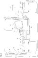
- the counter-spindle turning machine shown has a non-displaceable headstock 20 and a headstock 20a that can be displaced in the Z-direction.
- a workpiece spindle is mounted as a rotatable machine part 1 or 1a.
- the workpiece spindles carry clamping devices 21, 21a facing one another.
- the headstocks 20 and 20a are attached to a machine bed on which a longitudinal slide 3a can be moved in the Z-direction.
- a cross slide 3b is guided on the longitudinal slide 3a, on which a tool carrier is pivotably mounted about a horizontal axis.
- the tool carrier 24 has a tool holder into which tools (not shown), a probe 5 and a housing of a calibration gauge 4 can be inserted.
- a tool store 2 with storage locations 22 in the form of a tool magazine is arranged at one end of the counter-spindle lathe, in which a probe 5, the housing 9 and tools can be accommodated.
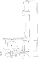
- FIG 2 illustrates the overall structure of a calibration device 19 according to the invention. It has a housing with a sleeve 11, which is followed by a holder shaft 14, at the end of which a short taper shaft 13 is formed is with which the calibration device 19 according to the invention can be inserted into the tool holder 10 .
- the sleeve 11 is made of CFRP material, but it can be made of another thin-walled material.
- the sleeve 11 protects a calibration standard 8, which is designed as a measuring ball and is accommodated in it, from contamination.
- the calibration device 19 according to the invention has a base 6 which is provided with magnetic feet 7 by means of which the calibration device 19 according to the invention can be fixed to the clamping device 21 .
- the mounting position of the calibration device 19 according to the invention in this exemplary embodiment is such that the calibration standard 8 is arranged concentrically to the axis of rotation of the rotatable machine part 1 .
- the short taper shank 13 and the holder shank 14 have a bore 15 through which sealing air is passed into the interior space formed by the sleeve 11 in order to prevent the ingress of dirt.
- the sleeve 11 is followed by a ring element 15 in which notches 12 are provided distributed over the circumference.
- the catches 12 hold the calibration gauge during transport in the sleeve 11 in such a way that the base 6 is freely accessible and can be fixed to the fastening device 21 with its magnetic feet 7 .
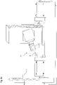
- the figures 4 and 5 and 6 and 7 illustrate different embodiments of the interface for attaching a part of the calibration device according to the invention to the machine section to be measured.
- figure 4 shows the part of the calibration device according to the invention to be fastened to the machine section, comprising the calibration standard and the interface for receiving it on the fastening device on the machine section, which is used in the exemplary embodiment of FIG figure 4 formed by a base 6 is, which has magnetic feet 7.
- the figure 5 shows this part of the calibration device according to the invention in cross section.
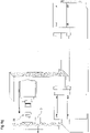
- Figure 8a shows the receiving of a calibration device 19 according to the invention, which is stored in a tool store 22, by a receiving device 24, which in this exemplary embodiment is designed as a tool carrier with a tool holder 10, which in this exemplary embodiment serves as an interface on the receiving device side for receiving the calibration device 19 according to the invention.
- a probe 5 is also mounted in the tool magazine 2 .
- the receiving device is moved via the two carriages 3a, 3b to a fastening position of the calibration device according to the invention in a fastening device on a tool section 21, as shown in FIG Figure 8b illustrated.
- the receiving device 24 in the present embodiment, the tool carrier with tool holder 10, after fixing of the part of the calibration device according to the invention with the calibration standard 8 removed from the machine section.
- the sleeve 11 with the interface of the calibration device according to the invention is pulled off for receiving on the receiving device in the form of the conical shank 13, so that the calibration standard 8 is exposed for measurement using the probe 5.
- this probe 5 is received by the receiving device in the tool magazine 2 and a sensor 5a is arranged in a measuring position B by moving the receiving device 24 in the vicinity of the calibration standard 8, which is designed as a measuring ball; see. Figure 8d .
- the workpiece spindle 1 is rotated and in this way brought the eccentrically arranged calibration standard into a second measuring position C, in which it is also measured by the probe.
- the Figures 8f and 8g illustrate the procedural steps of removing the calibration device according to the invention from the machine section to be measured by receiving the calibration standard 8 in the sleeve 11 and releasing it from the attachment to the machine section, which follows as a procedural step after the probe is placed in the tool magazine (not shown). Finally, as in Figure 8g illustrated, the entire calibration device according to the invention is stored in the tool magazine 2 .
- the present invention is not limited to this, but also includes configurations in which the entire calibration device according to the invention, including the interface is attached to the receiving device on the corresponding machine part for recording and remains there during the measuring process.
Landscapes
- Engineering & Computer Science (AREA)
- Physics & Mathematics (AREA)
- General Physics & Mathematics (AREA)
- Human Computer Interaction (AREA)
- Manufacturing & Machinery (AREA)
- Automation & Control Theory (AREA)
- Mechanical Engineering (AREA)
- Machine Tool Sensing Apparatuses (AREA)
Claims (14)
- Dispositif pour le relevé des cotes d'une machine-outil comprenant :- un système d'étalonnage (19), qui est conçu pour être fixé sur une section de la machine-outil, et- un capteur de mesure (5) pour la détection d'une position du système d'étalonnage (19) sur la machine-outil,dans lequel le système d'étalonnage (19) présente une interface (13), au moyen de laquelle le système d'étalonnage (19) peut être rentré et sorti de manière interchangeable dans un système de réception (24) déplaçable numériquement de la machine-outil, avec lequel le système d'étalonnage peut être transporté entre une position de mise à disposition et une position de fixation sur la section de la machine-outil,
caractérisé en ce quel'interface (13) présente pour la rentrée ou la sortie interchangeable dans le système de réception (24) un support, dans lequel un étalon d'étalonnage (8) du système d'étalonnage (19) peut être inséré,dans lequel le support présente un boîtier de protection (9) entourant l'étalon d'étalonnage (8). - Dispositif pour le relevé des cotes d'une machine-outil selon la revendication 1, caractérisé en ce que
l'étalon d'étalonnage (8) peut être fixé sur la section de machine au moyen d'une deuxième interface (6 ; 7 ; 6a). - Dispositif pour le relevé des cotes d'une machine-outil selon la revendication 1 ou 2, caractérisé en ce que
le système d'étalonnage (19) présente une structure en plusieurs parties, constituées d'une première partie, qui comprend l'interface (13) pour la réception sur le système de réception (24) et d'une deuxième partie pouvant être détachée de celle-ci, qui comprend l'étalon d'étalonnage (8) et l'interface (6, 7 ; 6a) pour la fixation sur une partie de machine (1). - Dispositif pour le relevé des cotes d'une machine-outil selon l'une quelconque des revendications 1 à 3, caractérisé en ce que
le boîtier de protection (9) est constitué d'un manchon (11) flexible à parois minces. - Dispositif pour le relevé des cotes d'une machine-outil selon l'une quelconque des revendications 1 à 4, caractérisé en ce que
le système d'étalonnage (19) est configuré de telle sorte qu'un signal pour commander un processus de déplacement du système de réception (24) est généré par une déformation du boîtier (9). - Dispositif pour le relevé des cotes d'une machine-outil selon l'une quelconque des revendications 1 à 5, caractérisé en ce que
le système d'étalonnage (19) présente un pied magnétique (7), au moyen duquel il peut être fixé sur la section de machine. - Dispositif pour le relevé des cotes d'une machine-outil selon l'une quelconque des revendications 1 à 6, caractérisé en ce que
le système d'étalonnage (19) présente une section de serrage, en particulier sous forme d'un socle (6a), au moyen de laquelle le système d'étalonnage (19) peut être serré sur la section de machine. - Dispositif pour le relevé des cotes d'une machine-outil selon l'une quelconque des revendications précédentes, caractérisé en ce que
le système d'étalonnage (19) est maintenu de manière détachable sur le support par des crans d'arrêt (12). - Système d'étalonnage (19) à insérer dans un dispositif pour le relevé des cotes d'une machine-outil selon l'une quelconque des revendications 1 à 8, dans lequel le système d'étalonnage (19) présente une interface (13), au moyen de laquelle le système d'étalonnage (19) peut être rentré ou sorti de manière interchangeable dans un système de réception (24) déplaçable numériquement de la machine-outil, dans lequel l'interface (13) présente pour la rentrée ou la sortie interchangeable dans le système de réception (24) un support, dans lequel un étalon d'étalonnage (8) du système d'étalonnage (19) peut être inséré, et dans lequel le support présente un boîtier de protection (9) entourant l'étalon d'étalonnage (8).
- Machine-outil avec un système d'étalonnage (19) selon la revendication 9,dans laquelle une section de machine (1), sur laquelle le système d'étalonnage (19) peut être fixé, comprend une broche porte-pièce rotative, etun système (21) pour la fixation du système d'étalonnage (19) sur la section de machine (1) dans une position excentrique par rapport à l'axe de la broche porte-pièce rotative.
- Machine-outil avec un système d'étalonnage (19) selon la revendication 9,
dans laquelle un système de réception (24) déplaçable numériquement de la machine-outil comprend un porte-outil (24) et au moins un chariot (3a, 3b), au moyen duquel celui-ci est déplaçable dans une position pour la fixation du système d'étalonnage (19) reçu dans le porte-outil (24) sur la section de machine (1). - Machine-outil avec un système d'étalonnage (19) selon la revendication 9,
dans laquelle un système de réception (24) déplaçable numériquement est réalisé sous la forme d'une broche, dans laquelle le système d'étalonnage (19) et un capteur de mesure (5) peuvent rentrer et sortir de manière interchangeable. - Procédé pour le relevé des cotes d'une machine-outil avec un système d'étalonnage (19), comprenant les étapes :- de fourniture d'un système d'étalonnage (19) selon la revendication 9 dans un magasin (2) pour la réception d'outils et/ou de pièces,- de déplacement d'un système de réception (24) dans une position proche du magasin (2) pour la réception du système d'étalonnage (19) et le prélèvement à partir du magasin (2),- de réception du système d'étalonnage (19) par le système de réception (24) et de déplacement du système de réception (24) dans une position proche d'un système (21) prévu sur une section de machine-outil (1) pour la fixation du système d'étalonnage (19) sur la section de machine (1),- de fixation du système d'étalonnage (19) sur la section de machine (1) par déplacement du système de réception (24) dans une position de fixation sur la section de machine (1) et réception dans un système de fixation (21) disposé sur la section de machine (1), et- de relevé d'une position du système d'étalonnage (19) sur la section de machine avec un capteur de mesure (5).
- Procédé selon la revendication 13, caractérisé en ce que l'étape de relevé d'une position du système d'étalonnage (19) sur la section de machine (1) avec le capteur de mesure (5) comprend les étapes suivantes :- le déplacement du système de réception (24) vers un magasin (2),- la réception du capteur de mesure (5) à partir du magasin (2),- le déplacement du système de réception (24) avec le capteur de mesure (5) dans une position de mesure proche du système d'étalonnage (19) fixé sur la section de machine (1),- le relevé de plusieurs positions d'un étalon d'étalonnage (8) du système d'étalonnage (19), et- la détermination d'une position de la section de machine (1) à partir des positions de mesure déterminées.
Priority Applications (1)
| Application Number | Priority Date | Filing Date | Title |
|---|---|---|---|
| EP17188015.6A EP3446830B1 (fr) | 2017-08-25 | 2017-08-25 | Dispositif et procédé de relevé d'une machine-outil |
Applications Claiming Priority (1)
| Application Number | Priority Date | Filing Date | Title |
|---|---|---|---|
| EP17188015.6A EP3446830B1 (fr) | 2017-08-25 | 2017-08-25 | Dispositif et procédé de relevé d'une machine-outil |
Publications (2)
| Publication Number | Publication Date |
|---|---|
| EP3446830A1 EP3446830A1 (fr) | 2019-02-27 |
| EP3446830B1 true EP3446830B1 (fr) | 2022-11-30 |
Family
ID=59702644
Family Applications (1)
| Application Number | Title | Priority Date | Filing Date |
|---|---|---|---|
| EP17188015.6A Active EP3446830B1 (fr) | 2017-08-25 | 2017-08-25 | Dispositif et procédé de relevé d'une machine-outil |
Country Status (1)
| Country | Link |
|---|---|
| EP (1) | EP3446830B1 (fr) |
Families Citing this family (1)
| Publication number | Priority date | Publication date | Assignee | Title |
|---|---|---|---|---|
| CN115422813B (zh) * | 2022-11-03 | 2023-02-10 | 北京精雕科技集团有限公司 | 面向机床公路运输工况的动力学分析方法及装置 |
Family Cites Families (4)
| Publication number | Priority date | Publication date | Assignee | Title |
|---|---|---|---|---|
| DE102005008055B4 (de) * | 2005-02-22 | 2009-01-02 | Deckel Maho Pfronten Gmbh | Verfahren zum Vermessen einer programmgesteuerten Werkzeugmaschine |
| GB0525306D0 (en) | 2005-12-13 | 2006-01-18 | Renishaw Plc | Method of machine tool calibration |
| SK288259B6 (sk) * | 2011-10-21 | 2015-04-01 | Microstep Spol. S R.O. | CNC stroj na rezanie plazmou, kyslíkom a vodným lúčom ako rezacím nástrojom s automatickým nastavovaním presnej polohy rezacieho nástroja v rezacej hlave autokalibráciou a spôsob takéhoto nastavovania |
| DE102015226387B4 (de) * | 2015-12-21 | 2023-07-27 | Carl Zeiss Industrielle Messtechnik Gmbh | Verfahren zur Durchführung von Messungen mit einem Prüfelement in einem Koordinatenmessgerät oder einer Werkzeugmaschine |
-
2017
- 2017-08-25 EP EP17188015.6A patent/EP3446830B1/fr active Active
Also Published As
| Publication number | Publication date |
|---|---|
| EP3446830A1 (fr) | 2019-02-27 |
Similar Documents
| Publication | Publication Date | Title |
|---|---|---|
| EP3048413B1 (fr) | Machine de mesure de pieces a usiner | |
| EP1554080B1 (fr) | Dispositif porte-outil et procede pour positionner un outil | |
| DE102013106427A1 (de) | Verfahren zum Bereitstellen von Werkmitteln und zugehörige Vorrichtungen | |
| WO2010000457A1 (fr) | Installation d'usinage de pièces | |
| DE102008055795A1 (de) | Schleifmaschine mit verfahrbarer Schleifeinheit | |
| DE19734301C1 (de) | Werkzeugmaschine zum Drehbearbeiten von wellenförmigen Werkstücken | |
| EP1892057B1 (fr) | Procédé de mesure d'outil à l'aide d'un appareil de mesure et dispositif de mesure doté d'un appareil de mesure pour la mesure d'outil | |
| DE8915924U1 (de) | Bohr- und Fräswerk | |
| DE102011082839A1 (de) | Handhabungsvorrichtung für eine Werkzeugmaschine | |
| EP0789221A2 (fr) | Méthode pour mesurer les coordonnées de pièces usinées sur des machines-outils | |
| DE102012105842B3 (de) | Werkzeugmaschine, insbesondere Schleifmaschine, sowie Verfahren zur spanenden Bearbeitung von Werkstücken | |
| DE69104639T2 (de) | Gerät zum Positionieren und Richten/Schleifen/Handhaben von Einkristall-Barren. | |
| EP2080585B1 (fr) | Dispositif de surveillance | |
| DE4414747A1 (de) | Meßwerkzeug, insbesondere für die Flächenvermessung | |
| EP3446830B1 (fr) | Dispositif et procédé de relevé d'une machine-outil | |
| DE102016220177A1 (de) | Verfahren zum Bearbeiten eines Bauteils und Bearbeitungsvorrichtung | |
| EP0260692A2 (fr) | Machine-outil avec un porte-broche à forer et à fraiser à déplacement dans la direction Z sur un châssis de machine | |
| DE102018104199B4 (de) | Werkzeugmaschine mit Arbeitsraum, Rüstplatz und Roboterarm und Verfahren zu deren Betrieb | |
| DE3634018C2 (fr) | ||
| DE112006003145B4 (de) | Zuführungsvorrichtung für ein Schneidwerkzeug zur Innenbearbeitung | |
| EP1169158B1 (fr) | Procede et dispositif destines a l'usinage de pieces | |
| WO2014147147A1 (fr) | Tour ou centre d'usinage horizontal servant à usiner des pièces à usiner ainsi que procédé servant à mesurer les pièces à usiner à l'aide d'un tour ou d'un centre d'usinage horizontal | |
| DE10361920B4 (de) | Vorrichtung und Verfahren zur Kontrolle von Werkzeugen | |
| DE102014115320A1 (de) | Koordinatenmessgerät zum Bestimmen von geometrischen Eigenschaften eines Messobjekts | |
| AT514068A4 (de) | Bestückungsvorrichtung für eine CAD/CAM-Fräseinrichtung |
Legal Events
| Date | Code | Title | Description |
|---|---|---|---|
| PUAI | Public reference made under article 153(3) epc to a published international application that has entered the european phase |
Free format text: ORIGINAL CODE: 0009012 |
|
| STAA | Information on the status of an ep patent application or granted ep patent |
Free format text: STATUS: THE APPLICATION HAS BEEN PUBLISHED |
|
| AK | Designated contracting states |
Kind code of ref document: A1 Designated state(s): AL AT BE BG CH CY CZ DE DK EE ES FI FR GB GR HR HU IE IS IT LI LT LU LV MC MK MT NL NO PL PT RO RS SE SI SK SM TR |
|
| AX | Request for extension of the european patent |
Extension state: BA ME |
|
| STAA | Information on the status of an ep patent application or granted ep patent |
Free format text: STATUS: REQUEST FOR EXAMINATION WAS MADE |
|
| 17P | Request for examination filed |
Effective date: 20190827 |
|
| RBV | Designated contracting states (corrected) |
Designated state(s): AL AT BE BG CH CY CZ DE DK EE ES FI FR GB GR HR HU IE IS IT LI LT LU LV MC MK MT NL NO PL PT RO RS SE SI SK SM TR |
|
| STAA | Information on the status of an ep patent application or granted ep patent |
Free format text: STATUS: EXAMINATION IS IN PROGRESS |
|
| 17Q | First examination report despatched |
Effective date: 20211020 |
|
| GRAP | Despatch of communication of intention to grant a patent |
Free format text: ORIGINAL CODE: EPIDOSNIGR1 |
|
| STAA | Information on the status of an ep patent application or granted ep patent |
Free format text: STATUS: GRANT OF PATENT IS INTENDED |
|
| INTG | Intention to grant announced |
Effective date: 20220706 |
|
| RIN1 | Information on inventor provided before grant (corrected) |
Inventor name: HALM, CHRISTIAN Inventor name: LITWINSKI, KAI Inventor name: BASSETT, EDMOND |
|
| GRAJ | Information related to disapproval of communication of intention to grant by the applicant or resumption of examination proceedings by the epo deleted |
Free format text: ORIGINAL CODE: EPIDOSDIGR1 |
|
| STAA | Information on the status of an ep patent application or granted ep patent |
Free format text: STATUS: EXAMINATION IS IN PROGRESS |
|
| GRAP | Despatch of communication of intention to grant a patent |
Free format text: ORIGINAL CODE: EPIDOSNIGR1 |
|
| INTC | Intention to grant announced (deleted) | ||
| STAA | Information on the status of an ep patent application or granted ep patent |
Free format text: STATUS: GRANT OF PATENT IS INTENDED |
|
| GRAS | Grant fee paid |
Free format text: ORIGINAL CODE: EPIDOSNIGR3 |
|
| GRAA | (expected) grant |
Free format text: ORIGINAL CODE: 0009210 |
|
| STAA | Information on the status of an ep patent application or granted ep patent |
Free format text: STATUS: THE PATENT HAS BEEN GRANTED |
|
| INTG | Intention to grant announced |
Effective date: 20221013 |
|
| AK | Designated contracting states |
Kind code of ref document: B1 Designated state(s): AL AT BE BG CH CY CZ DE DK EE ES FI FR GB GR HR HU IE IS IT LI LT LU LV MC MK MT NL NO PL PT RO RS SE SI SK SM TR |
|
| REG | Reference to a national code |
Ref country code: CH Ref legal event code: EP Ref country code: GB Ref legal event code: FG4D Free format text: NOT ENGLISH |
|
| REG | Reference to a national code |
Ref country code: AT Ref legal event code: REF Ref document number: 1534318 Country of ref document: AT Kind code of ref document: T Effective date: 20221215 Ref country code: DE Ref legal event code: R096 Ref document number: 502017014142 Country of ref document: DE |
|
| REG | Reference to a national code |
Ref country code: IE Ref legal event code: FG4D Free format text: LANGUAGE OF EP DOCUMENT: GERMAN |
|
| REG | Reference to a national code |
Ref country code: SE Ref legal event code: TRGR |
|
| REG | Reference to a national code |
Ref country code: NL Ref legal event code: FP |
|
| REG | Reference to a national code |
Ref country code: LT Ref legal event code: MG9D |
|
| PG25 | Lapsed in a contracting state [announced via postgrant information from national office to epo] |
Ref country code: PT Free format text: LAPSE BECAUSE OF FAILURE TO SUBMIT A TRANSLATION OF THE DESCRIPTION OR TO PAY THE FEE WITHIN THE PRESCRIBED TIME-LIMIT Effective date: 20230331 Ref country code: NO Free format text: LAPSE BECAUSE OF FAILURE TO SUBMIT A TRANSLATION OF THE DESCRIPTION OR TO PAY THE FEE WITHIN THE PRESCRIBED TIME-LIMIT Effective date: 20230228 Ref country code: LT Free format text: LAPSE BECAUSE OF FAILURE TO SUBMIT A TRANSLATION OF THE DESCRIPTION OR TO PAY THE FEE WITHIN THE PRESCRIBED TIME-LIMIT Effective date: 20221130 Ref country code: FI Free format text: LAPSE BECAUSE OF FAILURE TO SUBMIT A TRANSLATION OF THE DESCRIPTION OR TO PAY THE FEE WITHIN THE PRESCRIBED TIME-LIMIT Effective date: 20221130 Ref country code: ES Free format text: LAPSE BECAUSE OF FAILURE TO SUBMIT A TRANSLATION OF THE DESCRIPTION OR TO PAY THE FEE WITHIN THE PRESCRIBED TIME-LIMIT Effective date: 20221130 |
|
| PG25 | Lapsed in a contracting state [announced via postgrant information from national office to epo] |
Ref country code: RS Free format text: LAPSE BECAUSE OF FAILURE TO SUBMIT A TRANSLATION OF THE DESCRIPTION OR TO PAY THE FEE WITHIN THE PRESCRIBED TIME-LIMIT Effective date: 20221130 Ref country code: PL Free format text: LAPSE BECAUSE OF FAILURE TO SUBMIT A TRANSLATION OF THE DESCRIPTION OR TO PAY THE FEE WITHIN THE PRESCRIBED TIME-LIMIT Effective date: 20221130 Ref country code: LV Free format text: LAPSE BECAUSE OF FAILURE TO SUBMIT A TRANSLATION OF THE DESCRIPTION OR TO PAY THE FEE WITHIN THE PRESCRIBED TIME-LIMIT Effective date: 20221130 Ref country code: IS Free format text: LAPSE BECAUSE OF FAILURE TO SUBMIT A TRANSLATION OF THE DESCRIPTION OR TO PAY THE FEE WITHIN THE PRESCRIBED TIME-LIMIT Effective date: 20230330 Ref country code: HR Free format text: LAPSE BECAUSE OF FAILURE TO SUBMIT A TRANSLATION OF THE DESCRIPTION OR TO PAY THE FEE WITHIN THE PRESCRIBED TIME-LIMIT Effective date: 20221130 Ref country code: GR Free format text: LAPSE BECAUSE OF FAILURE TO SUBMIT A TRANSLATION OF THE DESCRIPTION OR TO PAY THE FEE WITHIN THE PRESCRIBED TIME-LIMIT Effective date: 20230301 |
|
| PG25 | Lapsed in a contracting state [announced via postgrant information from national office to epo] |
Ref country code: SM Free format text: LAPSE BECAUSE OF FAILURE TO SUBMIT A TRANSLATION OF THE DESCRIPTION OR TO PAY THE FEE WITHIN THE PRESCRIBED TIME-LIMIT Effective date: 20221130 Ref country code: RO Free format text: LAPSE BECAUSE OF FAILURE TO SUBMIT A TRANSLATION OF THE DESCRIPTION OR TO PAY THE FEE WITHIN THE PRESCRIBED TIME-LIMIT Effective date: 20221130 Ref country code: EE Free format text: LAPSE BECAUSE OF FAILURE TO SUBMIT A TRANSLATION OF THE DESCRIPTION OR TO PAY THE FEE WITHIN THE PRESCRIBED TIME-LIMIT Effective date: 20221130 Ref country code: DK Free format text: LAPSE BECAUSE OF FAILURE TO SUBMIT A TRANSLATION OF THE DESCRIPTION OR TO PAY THE FEE WITHIN THE PRESCRIBED TIME-LIMIT Effective date: 20221130 Ref country code: CZ Free format text: LAPSE BECAUSE OF FAILURE TO SUBMIT A TRANSLATION OF THE DESCRIPTION OR TO PAY THE FEE WITHIN THE PRESCRIBED TIME-LIMIT Effective date: 20221130 |
|
| PG25 | Lapsed in a contracting state [announced via postgrant information from national office to epo] |
Ref country code: SK Free format text: LAPSE BECAUSE OF FAILURE TO SUBMIT A TRANSLATION OF THE DESCRIPTION OR TO PAY THE FEE WITHIN THE PRESCRIBED TIME-LIMIT Effective date: 20221130 Ref country code: AL Free format text: LAPSE BECAUSE OF FAILURE TO SUBMIT A TRANSLATION OF THE DESCRIPTION OR TO PAY THE FEE WITHIN THE PRESCRIBED TIME-LIMIT Effective date: 20221130 |
|
| REG | Reference to a national code |
Ref country code: DE Ref legal event code: R097 Ref document number: 502017014142 Country of ref document: DE |
|
| PGFP | Annual fee paid to national office [announced via postgrant information from national office to epo] |
Ref country code: NL Payment date: 20230823 Year of fee payment: 7 |
|
| PLBE | No opposition filed within time limit |
Free format text: ORIGINAL CODE: 0009261 |
|
| STAA | Information on the status of an ep patent application or granted ep patent |
Free format text: STATUS: NO OPPOSITION FILED WITHIN TIME LIMIT |
|
| PGFP | Annual fee paid to national office [announced via postgrant information from national office to epo] |
Ref country code: AT Payment date: 20230818 Year of fee payment: 7 |
|
| 26N | No opposition filed |
Effective date: 20230831 |
|
| PG25 | Lapsed in a contracting state [announced via postgrant information from national office to epo] |
Ref country code: SI Free format text: LAPSE BECAUSE OF FAILURE TO SUBMIT A TRANSLATION OF THE DESCRIPTION OR TO PAY THE FEE WITHIN THE PRESCRIBED TIME-LIMIT Effective date: 20221130 |
|
| PGFP | Annual fee paid to national office [announced via postgrant information from national office to epo] |
Ref country code: SE Payment date: 20230823 Year of fee payment: 7 Ref country code: DE Payment date: 20230831 Year of fee payment: 7 |
|
| PG25 | Lapsed in a contracting state [announced via postgrant information from national office to epo] |
Ref country code: MC Free format text: LAPSE BECAUSE OF FAILURE TO SUBMIT A TRANSLATION OF THE DESCRIPTION OR TO PAY THE FEE WITHIN THE PRESCRIBED TIME-LIMIT Effective date: 20221130 |
|
| REG | Reference to a national code |
Ref country code: CH Ref legal event code: PL |
|
| PG25 | Lapsed in a contracting state [announced via postgrant information from national office to epo] |
Ref country code: MC Free format text: LAPSE BECAUSE OF FAILURE TO SUBMIT A TRANSLATION OF THE DESCRIPTION OR TO PAY THE FEE WITHIN THE PRESCRIBED TIME-LIMIT Effective date: 20221130 |
|
| PG25 | Lapsed in a contracting state [announced via postgrant information from national office to epo] |
Ref country code: LU Free format text: LAPSE BECAUSE OF NON-PAYMENT OF DUE FEES Effective date: 20230825 |
|
| GBPC | Gb: european patent ceased through non-payment of renewal fee |
Effective date: 20230825 |
|
| PG25 | Lapsed in a contracting state [announced via postgrant information from national office to epo] |
Ref country code: LU Free format text: LAPSE BECAUSE OF NON-PAYMENT OF DUE FEES Effective date: 20230825 Ref country code: CH Free format text: LAPSE BECAUSE OF NON-PAYMENT OF DUE FEES Effective date: 20230831 |
|
| REG | Reference to a national code |
Ref country code: BE Ref legal event code: MM Effective date: 20230831 |
|
| REG | Reference to a national code |
Ref country code: IE Ref legal event code: MM4A |
|
| PG25 | Lapsed in a contracting state [announced via postgrant information from national office to epo] |
Ref country code: IT Free format text: LAPSE BECAUSE OF FAILURE TO SUBMIT A TRANSLATION OF THE DESCRIPTION OR TO PAY THE FEE WITHIN THE PRESCRIBED TIME-LIMIT Effective date: 20221130 |
|
| PG25 | Lapsed in a contracting state [announced via postgrant information from national office to epo] |
Ref country code: IE Free format text: LAPSE BECAUSE OF NON-PAYMENT OF DUE FEES Effective date: 20230825 |
|
| PG25 | Lapsed in a contracting state [announced via postgrant information from national office to epo] |
Ref country code: GB Free format text: LAPSE BECAUSE OF NON-PAYMENT OF DUE FEES Effective date: 20230825 |
|
| PG25 | Lapsed in a contracting state [announced via postgrant information from national office to epo] |
Ref country code: GB Free format text: LAPSE BECAUSE OF NON-PAYMENT OF DUE FEES Effective date: 20230825 Ref country code: FR Free format text: LAPSE BECAUSE OF NON-PAYMENT OF DUE FEES Effective date: 20230831 Ref country code: IE Free format text: LAPSE BECAUSE OF NON-PAYMENT OF DUE FEES Effective date: 20230825 |
|
| PG25 | Lapsed in a contracting state [announced via postgrant information from national office to epo] |
Ref country code: BE Free format text: LAPSE BECAUSE OF NON-PAYMENT OF DUE FEES Effective date: 20230831 |
|
| PG25 | Lapsed in a contracting state [announced via postgrant information from national office to epo] |
Ref country code: BG Free format text: LAPSE BECAUSE OF FAILURE TO SUBMIT A TRANSLATION OF THE DESCRIPTION OR TO PAY THE FEE WITHIN THE PRESCRIBED TIME-LIMIT Effective date: 20221130 |
|
| PG25 | Lapsed in a contracting state [announced via postgrant information from national office to epo] |
Ref country code: BG Free format text: LAPSE BECAUSE OF FAILURE TO SUBMIT A TRANSLATION OF THE DESCRIPTION OR TO PAY THE FEE WITHIN THE PRESCRIBED TIME-LIMIT Effective date: 20221130 |
|
| REG | Reference to a national code |
Ref country code: DE Ref legal event code: R119 Ref document number: 502017014142 Country of ref document: DE |
|
| REG | Reference to a national code |
Ref country code: SE Ref legal event code: EUG |
|
| REG | Reference to a national code |
Ref country code: NL Ref legal event code: MM Effective date: 20240901 |
|
| REG | Reference to a national code |
Ref country code: AT Ref legal event code: MM01 Ref document number: 1534318 Country of ref document: AT Kind code of ref document: T Effective date: 20240825 |
|
| PG25 | Lapsed in a contracting state [announced via postgrant information from national office to epo] |
Ref country code: AT Free format text: LAPSE BECAUSE OF NON-PAYMENT OF DUE FEES Effective date: 20240825 |
|
| PG25 | Lapsed in a contracting state [announced via postgrant information from national office to epo] |
Ref country code: NL Free format text: LAPSE BECAUSE OF NON-PAYMENT OF DUE FEES Effective date: 20240901 |
|
| PG25 | Lapsed in a contracting state [announced via postgrant information from national office to epo] |
Ref country code: DE Free format text: LAPSE BECAUSE OF NON-PAYMENT OF DUE FEES Effective date: 20250301 |
|
| PG25 | Lapsed in a contracting state [announced via postgrant information from national office to epo] |
Ref country code: CY Free format text: LAPSE BECAUSE OF FAILURE TO SUBMIT A TRANSLATION OF THE DESCRIPTION OR TO PAY THE FEE WITHIN THE PRESCRIBED TIME-LIMIT; INVALID AB INITIO Effective date: 20170825 |
|
| PG25 | Lapsed in a contracting state [announced via postgrant information from national office to epo] |
Ref country code: HU Free format text: LAPSE BECAUSE OF FAILURE TO SUBMIT A TRANSLATION OF THE DESCRIPTION OR TO PAY THE FEE WITHIN THE PRESCRIBED TIME-LIMIT; INVALID AB INITIO Effective date: 20170825 |
|
| PG25 | Lapsed in a contracting state [announced via postgrant information from national office to epo] |
Ref country code: SE Free format text: LAPSE BECAUSE OF NON-PAYMENT OF DUE FEES Effective date: 20240826 |
|
| PG25 | Lapsed in a contracting state [announced via postgrant information from national office to epo] |
Ref country code: TR Free format text: LAPSE BECAUSE OF FAILURE TO SUBMIT A TRANSLATION OF THE DESCRIPTION OR TO PAY THE FEE WITHIN THE PRESCRIBED TIME-LIMIT Effective date: 20221130 |