EP1554411B1 - Herstellungsverfahren einer seltenerdelement enthaltende legierung - Google Patents
Herstellungsverfahren einer seltenerdelement enthaltende legierung Download PDFInfo
- Publication number
- EP1554411B1 EP1554411B1 EP03809445.4A EP03809445A EP1554411B1 EP 1554411 B1 EP1554411 B1 EP 1554411B1 EP 03809445 A EP03809445 A EP 03809445A EP 1554411 B1 EP1554411 B1 EP 1554411B1
- Authority
- EP
- European Patent Office
- Prior art keywords
- alloy
- containing alloy
- phase
- nazn
- producing
- Prior art date
- Legal status (The legal status is an assumption and is not a legal conclusion. Google has not performed a legal analysis and makes no representation as to the accuracy of the status listed.)
- Expired - Lifetime
Links
Images


Classifications
-
- C—CHEMISTRY; METALLURGY
- C22—METALLURGY; FERROUS OR NON-FERROUS ALLOYS; TREATMENT OF ALLOYS OR NON-FERROUS METALS
- C22C—ALLOYS
- C22C38/00—Ferrous alloys, e.g. steel alloys
- C22C38/005—Ferrous alloys, e.g. steel alloys containing rare earths, i.e. Sc, Y, Lanthanides
-
- B—PERFORMING OPERATIONS; TRANSPORTING
- B22—CASTING; POWDER METALLURGY
- B22D—CASTING OF METALS; CASTING OF OTHER SUBSTANCES BY THE SAME PROCESSES OR DEVICES
- B22D11/00—Continuous casting of metals, i.e. casting in indefinite lengths
- B22D11/001—Continuous casting of metals, i.e. casting in indefinite lengths of specific alloys
-
- B—PERFORMING OPERATIONS; TRANSPORTING
- B22—CASTING; POWDER METALLURGY
- B22D—CASTING OF METALS; CASTING OF OTHER SUBSTANCES BY THE SAME PROCESSES OR DEVICES
- B22D11/00—Continuous casting of metals, i.e. casting in indefinite lengths
- B22D11/06—Continuous casting of metals, i.e. casting in indefinite lengths into moulds with travelling walls, e.g. with rolls, plates, belts, caterpillars
- B22D11/0611—Continuous casting of metals, i.e. casting in indefinite lengths into moulds with travelling walls, e.g. with rolls, plates, belts, caterpillars formed by a single casting wheel, e.g. for casting amorphous metal strips or wires
-
- B—PERFORMING OPERATIONS; TRANSPORTING
- B22—CASTING; POWDER METALLURGY
- B22D—CASTING OF METALS; CASTING OF OTHER SUBSTANCES BY THE SAME PROCESSES OR DEVICES
- B22D11/00—Continuous casting of metals, i.e. casting in indefinite lengths
- B22D11/10—Supplying or treating molten metal
- B22D11/106—Shielding the molten jet
-
- C—CHEMISTRY; METALLURGY
- C21—METALLURGY OF IRON
- C21D—MODIFYING THE PHYSICAL STRUCTURE OF FERROUS METALS; GENERAL DEVICES FOR HEAT TREATMENT OF FERROUS OR NON-FERROUS METALS OR ALLOYS; MAKING METAL MALLEABLE, e.g. BY DECARBURISATION OR TEMPERING
- C21D6/00—Heat treatment of ferrous alloys
-
- C—CHEMISTRY; METALLURGY
- C22—METALLURGY; FERROUS OR NON-FERROUS ALLOYS; TREATMENT OF ALLOYS OR NON-FERROUS METALS
- C22C—ALLOYS
- C22C38/00—Ferrous alloys, e.g. steel alloys
- C22C38/02—Ferrous alloys, e.g. steel alloys containing silicon
-
- H—ELECTRICITY
- H01—ELECTRIC ELEMENTS
- H01F—MAGNETS; INDUCTANCES; TRANSFORMERS; SELECTION OF MATERIALS FOR THEIR MAGNETIC PROPERTIES
- H01F1/00—Magnets or magnetic bodies characterised by the magnetic materials therefor; Selection of materials for their magnetic properties
- H01F1/01—Magnets or magnetic bodies characterised by the magnetic materials therefor; Selection of materials for their magnetic properties of inorganic materials
- H01F1/012—Magnets or magnetic bodies characterised by the magnetic materials therefor; Selection of materials for their magnetic properties of inorganic materials adapted for magnetic entropy change by magnetocaloric effect, e.g. used as magnetic refrigerating material
- H01F1/015—Metals or alloys
-
- H—ELECTRICITY
- H01—ELECTRIC ELEMENTS
- H01F—MAGNETS; INDUCTANCES; TRANSFORMERS; SELECTION OF MATERIALS FOR THEIR MAGNETIC PROPERTIES
- H01F1/00—Magnets or magnetic bodies characterised by the magnetic materials therefor; Selection of materials for their magnetic properties
- H01F1/01—Magnets or magnetic bodies characterised by the magnetic materials therefor; Selection of materials for their magnetic properties of inorganic materials
- H01F1/03—Magnets or magnetic bodies characterised by the magnetic materials therefor; Selection of materials for their magnetic properties of inorganic materials characterised by their coercivity
- H01F1/032—Magnets or magnetic bodies characterised by the magnetic materials therefor; Selection of materials for their magnetic properties of inorganic materials characterised by their coercivity of hard-magnetic materials
- H01F1/04—Magnets or magnetic bodies characterised by the magnetic materials therefor; Selection of materials for their magnetic properties of inorganic materials characterised by their coercivity of hard-magnetic materials metals or alloys
- H01F1/047—Alloys characterised by their composition
- H01F1/053—Alloys characterised by their composition containing rare earth metals
- H01F1/055—Alloys characterised by their composition containing rare earth metals and magnetic transition metals, e.g. SmCo5
- H01F1/0551—Alloys characterised by their composition containing rare earth metals and magnetic transition metals, e.g. SmCo5 in the form of particles, e.g. rapid quenched powders or ribbon flakes
-
- H—ELECTRICITY
- H01—ELECTRIC ELEMENTS
- H01F—MAGNETS; INDUCTANCES; TRANSFORMERS; SELECTION OF MATERIALS FOR THEIR MAGNETIC PROPERTIES
- H01F41/00—Apparatus or processes specially adapted for manufacturing or assembling magnets, inductances or transformers; Apparatus or processes specially adapted for manufacturing materials characterised by their magnetic properties
- H01F41/02—Apparatus or processes specially adapted for manufacturing or assembling magnets, inductances or transformers; Apparatus or processes specially adapted for manufacturing materials characterised by their magnetic properties for manufacturing cores, coils, or magnets
- H01F41/0253—Apparatus or processes specially adapted for manufacturing or assembling magnets, inductances or transformers; Apparatus or processes specially adapted for manufacturing materials characterised by their magnetic properties for manufacturing cores, coils, or magnets for manufacturing permanent magnets
- H01F41/0266—Moulding; Pressing
-
- H—ELECTRICITY
- H10—SEMICONDUCTOR DEVICES; ELECTRIC SOLID-STATE DEVICES NOT OTHERWISE PROVIDED FOR
- H10N—ELECTRIC SOLID-STATE DEVICES NOT OTHERWISE PROVIDED FOR
- H10N35/00—Magnetostrictive devices
- H10N35/80—Constructional details
- H10N35/85—Magnetostrictive active materials
-
- B—PERFORMING OPERATIONS; TRANSPORTING
- B22—CASTING; POWDER METALLURGY
- B22F—WORKING METALLIC POWDER; MANUFACTURE OF ARTICLES FROM METALLIC POWDER; MAKING METALLIC POWDER; APPARATUS OR DEVICES SPECIALLY ADAPTED FOR METALLIC POWDER
- B22F9/00—Making metallic powder or suspensions thereof
- B22F9/02—Making metallic powder or suspensions thereof using physical processes
- B22F9/04—Making metallic powder or suspensions thereof using physical processes starting from solid material, e.g. by crushing, grinding or milling
- B22F2009/041—Making metallic powder or suspensions thereof using physical processes starting from solid material, e.g. by crushing, grinding or milling by mechanical alloying, e.g. blending, milling
-
- B—PERFORMING OPERATIONS; TRANSPORTING
- B22—CASTING; POWDER METALLURGY
- B22F—WORKING METALLIC POWDER; MANUFACTURE OF ARTICLES FROM METALLIC POWDER; MAKING METALLIC POWDER; APPARATUS OR DEVICES SPECIALLY ADAPTED FOR METALLIC POWDER
- B22F2998/00—Supplementary information concerning processes or compositions relating to powder metallurgy
- B22F2998/10—Processes characterised by the sequence of their steps
-
- B—PERFORMING OPERATIONS; TRANSPORTING
- B22—CASTING; POWDER METALLURGY
- B22F—WORKING METALLIC POWDER; MANUFACTURE OF ARTICLES FROM METALLIC POWDER; MAKING METALLIC POWDER; APPARATUS OR DEVICES SPECIALLY ADAPTED FOR METALLIC POWDER
- B22F2999/00—Aspects linked to processes or compositions used in powder metallurgy
-
- C—CHEMISTRY; METALLURGY
- C21—METALLURGY OF IRON
- C21D—MODIFYING THE PHYSICAL STRUCTURE OF FERROUS METALS; GENERAL DEVICES FOR HEAT TREATMENT OF FERROUS OR NON-FERROUS METALS OR ALLOYS; MAKING METAL MALLEABLE, e.g. BY DECARBURISATION OR TEMPERING
- C21D8/00—Modifying the physical properties of ferrous metals or ferrous alloys by deformation combined with, or followed by, heat treatment
- C21D8/12—Modifying the physical properties of ferrous metals or ferrous alloys by deformation combined with, or followed by, heat treatment during manufacturing of articles with special electromagnetic properties
- C21D8/1205—Modifying the physical properties of ferrous metals or ferrous alloys by deformation combined with, or followed by, heat treatment during manufacturing of articles with special electromagnetic properties involving particular fabrication steps or treatments of ingots or slabs
- C21D8/1211—Rapid solidification; Thin strip casting
-
- F—MECHANICAL ENGINEERING; LIGHTING; HEATING; WEAPONS; BLASTING
- F25—REFRIGERATION OR COOLING; COMBINED HEATING AND REFRIGERATION SYSTEMS; HEAT PUMP SYSTEMS; MANUFACTURE OR STORAGE OF ICE; LIQUEFACTION SOLIDIFICATION OF GASES
- F25B—REFRIGERATION MACHINES, PLANTS OR SYSTEMS; COMBINED HEATING AND REFRIGERATION SYSTEMS; HEAT PUMP SYSTEMS
- F25B21/00—Machines, plants or systems, using electric or magnetic effects
-
- H—ELECTRICITY
- H01—ELECTRIC ELEMENTS
- H01F—MAGNETS; INDUCTANCES; TRANSFORMERS; SELECTION OF MATERIALS FOR THEIR MAGNETIC PROPERTIES
- H01F1/00—Magnets or magnetic bodies characterised by the magnetic materials therefor; Selection of materials for their magnetic properties
- H01F1/01—Magnets or magnetic bodies characterised by the magnetic materials therefor; Selection of materials for their magnetic properties of inorganic materials
- H01F1/03—Magnets or magnetic bodies characterised by the magnetic materials therefor; Selection of materials for their magnetic properties of inorganic materials characterised by their coercivity
- H01F1/032—Magnets or magnetic bodies characterised by the magnetic materials therefor; Selection of materials for their magnetic properties of inorganic materials characterised by their coercivity of hard-magnetic materials
- H01F1/04—Magnets or magnetic bodies characterised by the magnetic materials therefor; Selection of materials for their magnetic properties of inorganic materials characterised by their coercivity of hard-magnetic materials metals or alloys
- H01F1/047—Alloys characterised by their composition
- H01F1/053—Alloys characterised by their composition containing rare earth metals
- H01F1/055—Alloys characterised by their composition containing rare earth metals and magnetic transition metals, e.g. SmCo5
- H01F1/057—Alloys characterised by their composition containing rare earth metals and magnetic transition metals, e.g. SmCo5 and IIIa elements, e.g. Nd2Fe14B
- H01F1/0571—Alloys characterised by their composition containing rare earth metals and magnetic transition metals, e.g. SmCo5 and IIIa elements, e.g. Nd2Fe14B in the form of particles, e.g. rapid quenched powders or ribbon flakes
- H01F1/0575—Alloys characterised by their composition containing rare earth metals and magnetic transition metals, e.g. SmCo5 and IIIa elements, e.g. Nd2Fe14B in the form of particles, e.g. rapid quenched powders or ribbon flakes pressed, sintered or bonded together
- H01F1/0577—Alloys characterised by their composition containing rare earth metals and magnetic transition metals, e.g. SmCo5 and IIIa elements, e.g. Nd2Fe14B in the form of particles, e.g. rapid quenched powders or ribbon flakes pressed, sintered or bonded together sintered
-
- H—ELECTRICITY
- H01—ELECTRIC ELEMENTS
- H01F—MAGNETS; INDUCTANCES; TRANSFORMERS; SELECTION OF MATERIALS FOR THEIR MAGNETIC PROPERTIES
- H01F1/00—Magnets or magnetic bodies characterised by the magnetic materials therefor; Selection of materials for their magnetic properties
- H01F1/01—Magnets or magnetic bodies characterised by the magnetic materials therefor; Selection of materials for their magnetic properties of inorganic materials
- H01F1/03—Magnets or magnetic bodies characterised by the magnetic materials therefor; Selection of materials for their magnetic properties of inorganic materials characterised by their coercivity
- H01F1/032—Magnets or magnetic bodies characterised by the magnetic materials therefor; Selection of materials for their magnetic properties of inorganic materials characterised by their coercivity of hard-magnetic materials
- H01F1/04—Magnets or magnetic bodies characterised by the magnetic materials therefor; Selection of materials for their magnetic properties of inorganic materials characterised by their coercivity of hard-magnetic materials metals or alloys
- H01F1/047—Alloys characterised by their composition
- H01F1/053—Alloys characterised by their composition containing rare earth metals
- H01F1/055—Alloys characterised by their composition containing rare earth metals and magnetic transition metals, e.g. SmCo5
- H01F1/058—Alloys characterised by their composition containing rare earth metals and magnetic transition metals, e.g. SmCo5 and IVa elements, e.g. Gd2Fe14C
-
- Y—GENERAL TAGGING OF NEW TECHNOLOGICAL DEVELOPMENTS; GENERAL TAGGING OF CROSS-SECTIONAL TECHNOLOGIES SPANNING OVER SEVERAL SECTIONS OF THE IPC; TECHNICAL SUBJECTS COVERED BY FORMER USPC CROSS-REFERENCE ART COLLECTIONS [XRACs] AND DIGESTS
- Y02—TECHNOLOGIES OR APPLICATIONS FOR MITIGATION OR ADAPTATION AGAINST CLIMATE CHANGE
- Y02B—CLIMATE CHANGE MITIGATION TECHNOLOGIES RELATED TO BUILDINGS, e.g. HOUSING, HOUSE APPLIANCES OR RELATED END-USER APPLICATIONS
- Y02B30/00—Energy efficient heating, ventilation or air conditioning [HVAC]
Definitions
- the present invention relates to a method for producing an alloy containing a rare earth element (hereinafter referred to as RE-containing alloy). More particularly, the invention relates to a technique for producing an NaZn 13 -type RE-containing alloy which is suitable for producing a magnetostrictive device, a magnetic refrigerant, etc.
- RE-containing alloy a rare earth element
- the invention relates to a technique for producing an NaZn 13 -type RE-containing alloy which is suitable for producing a magnetostrictive device, a magnetic refrigerant, etc.
- Magnetostrictive devices which generate strain through application of a magnetic field, are employed as magnetostrictive sensors, magnetostrictive vibrators, and similar devices for generating or detecting displacement with precision.
- RE-containing intermetallic compounds such as TbFe 2 , DyFe 2 , and SmFe 2 are employed as magnetostrictive materials.
- these intermetallic compounds generate only minute displacement, and precise control of the generated displacement is difficult. Therefore, these compounds cannot be applied to magneto-displacement devices for controlling minute displacement.
- GGG gallium gadolinium garnet
- GGG has not yet been used in a commercial product, because of its poor refrigeration efficiency upon application of a weak magnetic field provided by a permanent magnet.
- NiZn 13 -type RE-containing alloy an RE-containing alloy having an NaZn 13 phase
- this type of alloy is thought to be a candidate magnetostrictive material, magnetic refrigerant, etc.
- La(Fe a Si 1-a ) 13 (0.84 ⁇ a ⁇ 0.88) is disclosed to exhibit a magnetostrain as large as about 0.4% at 200 K under ⁇ 4T (see, for example, non-patent reference 1).
- Curie temperature can be controlled and magnetocaloric effect can be maintained at a high level (see, for example, non-patent reference 2).
- NaZn 13 -type RE-containing alloys such as La(Fe a Si 1-a ) 13 (0.84 ⁇ a ⁇ 0.88) have been produced by weighing alloy raw materials such as high-purity La, Fe, Si, etc., so as to attain a desired alloy composition and mixing; melting the mixture through arc melting; and heating the product for a considerably long period of time (e.g., at 1,050°C for 1,000 hours) in order to remove an undesired phase (see, for example, non-patent reference 2).
- the long-term heat treatment step for removing an undesired phase lowers productivity and increases costs in the production of NaZn 13 -type RE-containing alloys, devices employing the alloys, and other products employing the alloys.
- an La-Fe-Si alloy has been found to exhibit magnetic phase transition concomitant with a large entropy change in accordance with a change in the external magnetic field and to have no temperature hysteresis in the magnetocaloric effect.
- this type of alloy is considered a candidate magnetic refrigerant.
- the magnetic phase transition temperature of the La-Fe-Si alloy can be controlled by absorbing hydrogen into the alloy, and the change in entropy does not decrease even when hydrogen is absorbed (see non-patent reference 2). Therefore, when the magnetic phase transition temperature of the alloy is controlled to approximately room temperature and a permanent magnet is employed to generate a magnetic field, the alloy can be used as a magnetic refrigerant which can work at about room temperature.
- this type of alloy which exhibits a large, isotropic volume change under application of an external magnetic field, is also considered a candidate magnetostrictive material (see non-patent reference 1).
- a conventionally known method for producing an La-Fe-Si alloy having an NaZn 13 structure includes arc-melting raw material metals (i.e., La, Fe, and Si), to thereby form an alloy ingot; heating the alloy ingot in an inert atmosphere at 1,000 to 1,200°C for 240 hours to 1,000 hours, to thereby form a mother alloy; re-melting the mother alloy; atomizing the formed molten alloy in an atmosphere for cooling, to thereby produce spherical particles; and absorbing hydrogen into the particles, to thereby control the magnetic phase transition temperature to a predetermined level (see patent reference 1).
- raw material metals i.e., La, Fe, and Si
- the aforementioned conventional method for producing an RE-containing alloy powder has a drawback. Namely, since the method includes a long-term heat treatment and two melting steps, production costs increase and oxygen content of the alloy increases, even though low-cost material is used.
- an object of the present invention is to provide a technique capable of producing an NaZn 13 -type RE-containing alloy at high efficiency without performing a long-period heat treatment step.
- the present inventor has carried out extensive studies in order to solve the aforementioned problem, and has discovered the following method for producing an RE-containing alloy.
- the present invention comprises the following items (1) to (7).
- the first method of the present invention for producing a first RE-containing alloy is directed to a method for producing a starting alloy (the first RE-containing alloy) for an NaZn 13 -type RE-containing alloy that is represented by formula R(T 1-x A x ) 13-y (wherein R represents at least one rare earth metal selected from among La, Ce, Pr, Nd, Sm, Eu, Tb, Dy, Ho, Tm, Yb, Gd, and Lu; T represents at least one transition metal selected from among Fe, Co, Ni, Mn, Pt, and Pd; and A represents at least one element selected from among Al, As, Si, Ga, Ge, Mn, Sn, and Sb, and 0.05 ⁇ x ⁇ 0.2; and -1 ⁇ y ⁇ 1).
- R represents at least one rare earth metal selected from among La, Ce, Pr, Nd, Sm, Eu, Tb, Dy, Ho, Tm, Yb, Gd, and Lu
- T represents at least one transition metal selected from among Fe,
- the method generally includes a melting step (1) of melting an alloy raw material; and a solidification step (2) of solidifying the molten metal produced through the above step, to thereby form an RE-containing alloy (the first RE-containing alloy), wherein the solidification is performed through the "rapid quenching method.”
- alloy raw materials i.e., materials containing a rare earth metal (R), a transition metal (T), and an element (A), respectively, are mixed, and the mixture is melted.
- the material containing a rare earth element R
- the material predominantly contains at least one species selected from among La, Ce, Pr, Nd, Sm, Eu, Tb, Dy, Ho, Tm, Yb, Gd, and Lu.
- examples of such materials which can be employed include rare earth metals (purity: ⁇ 90 mass%, the balance being unavoidable impurities such as Al, Fe, Mo, W, C, O, or N) and misch metals predominantly containing La, Ce, etc. (rare earth metal content: ⁇ 90 mass%, the balance being unavoidable impurities such as Al, Fe, Mo, W, C, O, or N).
- T transition metal
- the material containing a transition metal (T) so long as the material predominantly contains at least one species selected from among Fe, Co, Ni, Mn, Pt, and Pd.
- materials which can be employed include pure metals such as Fe, Co, and Ni (purity: ⁇ 99 mass%).
- the material containing an element (A) is imposed on the material containing an element (A), so long as the material predominantly contains at least one species selected from among Al, As, Si, Ga, Ge, Mn, Sn, and Sb.
- materials which can be employed include metallic silicon (purity: ⁇ 95 mass%, the balance being unavoidable impurities such as Pb, As, Fe, Cu, Bi, Ni, C, O, or N), metallic Ga, and pure Al.
- the compositional proportions in terms of La, Fe, and Si contained in the raw materials preferably fall within the ranges of 16.8 to 17.3 mass%, 78.3 to 80.1 mass%, and 4.8 to 5.0 mass%, respectively.
- the thus-produced alloy material mixture is melted by heating at 1,200 to 1,800°C.
- the melting is preferably performed in an inert gas atmosphere at 0.1 MPa (atmospheric pressure) to 0.2 MPa.
- the inert gas include Ar and He.
- a heating temperature lower than 1,200°C is not preferred because an undesired phase other than the R-rich phase and the R-poor phase may be formed, whereas a heating temperature higher than 1,800°C is not preferred, because vaporization of a rare earth metal is promoted excessively, leading to difficulty in controlling the alloy composition.
- An inert gas atmosphere pressure lower than 0.1 MPa is not preferred, because vaporization of a rare earth metal is promoted excessively, leading to difficulty in controlling the alloy composition, whereas an inert gas atmosphere pressure higher than 0.2 MPa is not preferred, because the inert gas tends to migrate into the molten metal, thereby yielding an alloy having a large number of pores.
- the molten metal produced through the above melting step is rapidly quenched, to thereby form an RE-containing alloy. Rapid quenching may be performed through strip casting, new centrifugal casting (employing a tundish of a rotatable disk type), centrifugal casting, or a similar method.
- the solidification step is performed at a cooling rate of 10 2 to 10 4 °C/second, preferably 5 x 10 2 to 3 x 10 3 °C/second, as measured at least within a range of the temperature of the molten metal to 900°C.
- the present inventor has found that a uniform alloy metallographic microstructure which includes a crystalline phase can be formed by controlling the cooling rate in the above manner. More specifically, the inventor has found that there can be produced an RE-containing alloy which includes an R-rich phase (relatively high rare earth metal (R) content) and an R-poor phase (relatively low rare earth metal (R) content), with each phase being minute and being dispersed at a small phase spacing of 0.01 to 100 ⁇ m.
- R-rich phase relatively high rare earth metal (R) content
- R-poor phase relatively low rare earth metal (R) content
- the inventor has also found that the R-rich phase and the R-poor phase are transformed into an NaZn 13 phase by heating the RE-containing alloy within a period of time as short as 200 hours or less, to thereby effectively produce an NaZn 13 -type RE-containing alloy.
- the reason for the effective production of the alloy is that atoms for forming the NaZn 13 phase are effectively diffused, to thereby complete NaZn 13 phase formation within a shorter period than in conventional methods.
- the cooling rate as measured within a range of the temperature of the molten metal to 900°C is less than 10 2 °C/second, the size and phase spacing of the R-rich phase and the R-poor phase increases, leading to difficulty in formation of a uniform NaZn 13 phase through heat treatment, although an alloy microstructure including the R-rich phase and the R-poor phase is formed.
- the cooling rate as measured within the same range is more than 10 4 °C/second, the formed alloy microstructure includes an amorphous phase containing a transition metal (T), leading to considerable deterioration in pulverization and processing characteristics. These two cases are not preferred.
- an exemplary production apparatus suitably used in the first method of the present invention for producing an RE-containing alloy will be briefly described, taking as an example the case in which rapid quenching is performed through the strip casting method.
- FIG 1 shows the above apparatus including a crucible 1, a tundish 2, a cooling roller 3, and a receiving box 4.
- alloy raw materials are melted in the crucible 1, whereby a molten metal 5 is formed.
- the formed molten metal 5 is poured via the tundish 2 onto the cylindrical cooling roller 3, which is rotating in a predetermined direction (counterclockwise in FIG. 1 ).
- the cooling roller 3 is formed of a copper roller or the like cooled by water or a similar medium.
- the molten metal 5 is rapidly quenched to 900°C or lower through contact with the roller, to thereby form an alloy.
- the rate for cooling the molten metal 5 can be regulated by modifying the rotating speed (as represented by peripheral velocity) of the cooling roller 3; modifying the amount of the molten metal poured onto the cooling roller 3; or modifying a similar parameter.
- the thickness of the formed alloy strips 6 is preferably regulated to 0.1 to 2.0 mm by modifying the amount of the molten metal poured onto the cooling roller 3 or a similar parameter. Regulation of the thickness of the alloy strips 6 within the above range provides an RE-containing alloy which is formed of an R-rich phase and an R-poor phase, the phases having a minute size and being dispersed at a minute phase spacing, and which has an excellent pulverization characteristic.
- the thus-collected strips 6 are cooled in the receiving box 4 to room temperature, and then removed from the receiving box.
- the rate of cooling the alloy collected in the receiving box 4 is preferably controlled through thermal insulation or forced cooling of the receiving box 4.
- uniformity in the alloy microstructure can be further enhanced.
- the second method of the present invention for producing an RE-containing alloy is directed to a method for producing an NaZn 13 -type RE-containing alloy from a starting alloy for an NaZn 13 -type RE-containing alloy produced through the first method for producing an RE-containing alloy.
- the production method includes a heat treatment step (3) of heating the starting alloy for NaZn 13 -type RE-containing alloy that is produced through the aforementioned first method. More specifically, the heat treatment step includes heating at 900 to 1,200°C the starting alloy for NaZn 13 -type RE-containing alloy that is produced through the aforementioned first method, to thereby form an NaZn 13 phase.
- the heat treatment is preferably performed under reduced pressure or in vacuum.
- the present inventor has found that the R-rich phase and the R-poor phase are transformed into an NaZn 13 phase by heating the RE-containing alloy at 900 to 1,200°C for a short period of time falling within a range of one minute to 200 hours, to thereby produce an NaZn 13 -type RE-containing alloy at remarkably high efficiency.
- the inventor has also found that the produced NaZn 13 -type RE-containing alloy has an NaZn 13 phase content of at least 90 vol.%.
- the ratio of the volume of NaZn 13 phase contained in the alloy to that of non-NaZn 13 phase(s) can be determined by identifying each crystal phase through powder x-ray diffractometry; calculating the ratio of "area of the NaZn 13 phase” to "area exhibiting contrast differing from that of the NaZn 13 phase,” on the basis of a back-scattered electron image observed under a scanning electron microscope; and converting the area ratio to the corresponding volume ratio.
- the method according to the present invention includes rapid quenching, under predetermined conditions, of the molten metal produced by melting raw materials. Therefore, the method provides a starting alloy for an NaZn 13 -type RE-containing alloy having an alloy microstructure in which an R-rich phase and an R-poor phase are minutely and uniformly dispersed and being suitable for producing an NaZn 13 -type RE-containing alloy. From the starting alloy, an NaZn 13 -type RE-containing alloy can be produced through heat treatment for a short period of time of 200 hours or less.
- productivity in the production of an NaZn 13 -type RE-containing alloy and devices and other products fabricated by use of the alloy can be remarkably enhanced, and production costs can be remarkably reduced.
- the starting alloy in which the R-rich phase and the R-poor phase are minutely and uniformly dispersed also has an excellent pulverization characteristic. Therefore, the starting alloy has excellent processability and is readily formed into a desired shape through pulverization, compacting, and sintering. Thus, an NaZn 13 -type RE-containing alloy product having a desired shape can be readily produced from the corresponding starting alloy of the same shape.
- a high-quality NaZn 13 -type RE-containing alloy having an NaZn 13 phase content of 90 vol.% or higher can be provided.
- high-performance magnetostrictive devices and magnetic refrigerants can be provided.
- a third RE-containing alloy, an alloy powder comprising the third RE-containing alloy, and a method for producing the alloy powder (not covered by the scope of the present invention).
- a third RE-containing alloy comprising a rare earth element R (wherein R represents at least one species selected from among La, Ce, Pr, Nd, Sm, Eu, Tb, Dy, Ho, Tm, Yb, Gd, and Lu); a transition metal element T (wherein T collectively represents transition metal elements containing at least Fe atoms, a portion of the Fe atoms being optionally substituted by at least one species selected from among Co, Ni, Mn, Pt, and Pd); and other elements A (wherein A represents at least one species selected from among Al, As, Si, Ga, Ge, Mn, Sn, and Sb); having a composition (atomic percentage of R, T, and A represented by r, t, and a, which have the following relationships: 5.0 at.% ⁇ r ⁇ 6.8 at.%, 73.8 at.% ⁇ t ⁇ 88.7 at.%, and 4.6 at.% ⁇ a ⁇ 19.4 at.%), and having an alloy microstructure
- the aforementioned rare earth elements R, transition metal elements T, and other elements A are essential for producing an alloy having an NaZn 13 -type crystal structure.
- compositional proportions (rare earth element R, transition metal element T, and other element(s) A) suitable for producing the above alloy are considered to be the following: 5.5 at.% ⁇ r ⁇ 7.1 at.%, 73.8 at.% ⁇ t ⁇ 88.7 at.%, and 4.6 at.% ⁇ a ⁇ 19.4 at.%.
- the proportion of the rare earth element R contained in the alloy is regulated to 5.0 at.% ⁇ r ⁇ 6.8 at.%, which is less than the theoretical range.
- ⁇ -Fe remains in the RE-containing alloy in an amount of 5 mass% or more, whereby mechanical strength of the sintered RE-containing alloy which has undergone hydrogen absorption can be maintained.
- the third RE-containing alloy in some cases contains impurities such as O, C, and N.
- the amount of each impurity i.e., O, C, or N, is preferably 1 mass% or less and as small as possible.
- the third RE-containing alloy is preferably cast through rapid quenching so as to conveniently form, through heat treatment, an RE-containing alloy having an alloy microstructure containing an NaZn 13 -type crystal structure in an amount of at least 85 mass%.
- rapid quenching methods include strip casting (SC) and centrifugal casting. Taking the SC method as an example, casting of the RE-containing alloy will be described in detail.
- the alloy raw material is melted in the crucible 1 at 1,500°C to 1,800°C under inert gas such as Ar or He.
- the molten alloy 5, prepared by melting the alloy raw material is poured via the tundish 2 onto the copper roller 3, which is cooled by water and is rotating in a direction indicated by the arrow shown in FIG 1 , to thereby rapidly quench the alloy.
- the cooling rate as measured within a range of the temperature of the molten alloy to 900°C, is controlled to 10 2 to 10 4 °C/second, preferably to 5 x 10 2 °C/second to 3 x 10 3 °C/second. By controlling the cooling rate in such a manner, a uniform alloy micro-structure having a crystalline phase can be readily formed.
- the thus-produced alloy may also be called "RE-containing alloy which has not yet undergone heat treatment".
- the cooling rate is less than 102 ° C/second, the R-rich phase spacing, the R-poor phase spacing, and the size of each phase increase. In this case, even when a subsequent heat treatment is performed, a uniform NaZn 13 -type crystal structure is difficult to form.
- the cooling rate is in excess of 10 4 °C/second, the formed alloy assumes a mixture of amorphous metal and Fe, resulting in poor productivity. Both cases are not preferred.
- the molten alloy cooling rate can be controlled to a desired value by modifying the rotating speed (as represented by peripheral velocity) of the copper roller 3 or by modifying the amount of the molten alloy poured onto the copper roller 3.
- FIG. 2 is a back-scattered electron image of a cross-section of a sample of La(Fe 0.89 Si 0.11 ) 13 alloy, which is an example of an alloy having a composition of R r T t A a cast through the above rapid quenching method.
- a portion having a large average atomic weight is observed as a white image
- a portion having a small average atomic weight is observed as a black image.
- the R-rich phase having a high rare earth metal content
- the R-poor phase having a rare earth metal content lower than that of the R-rich phase
- the alloy produced through the aforementioned rapid quenching method is formed of an R-rich phase, having a relatively high rare earth metal content, and an R-poor phase, having a relatively low rare earth metal content.
- the back-scattered electron image of FIG. 2 indicates that the R-rich phase (white image) has a size of 5 ⁇ m or less, that the R-poor phase (gray image) has a diameter of 10 ⁇ m or less, and that the phases are uniformly distributed in the microstructure.
- each of the R-rich phase and R-poor phase has a size (diameter) of 30 ⁇ m or less, preferably 10 ⁇ m or less.
- both phases are uniformly dispersed in the structure.
- the diffusion path of elements between the R-rich phase and the R-poor phase is shortened.
- ⁇ -Fe can be dispersed minutely and uniformly through heat treatment carried out for a short period of time.
- an RE-containing alloy containing an NaZn 13 -type crystal structure in an amount of 85 mass% or more can be readily produced through heat treatment carried out for a short period of time.
- An RE-containing alloy containing an R-rich phase and an R-poor phase each having a size (diameter) of 30 ⁇ m or less can be reliably produced by casting through rapid quenching at a cooling rate of 10 2 to 10 4 °C/second, as measured within a range of the temperature of the molten alloy to 900°C.
- FIG 3 is an X-ray diffraction chart of an alloy powder which has been produced by casting the alloy through strip casting, followed by heat treatment at 1,100°C for 12 hours.
- the alloy shown in FIG. 3 has been produced from La, Fe, and Si serving as raw materials of components R, T, and A, respectively.
- the amount of NaZn 13 -structure La(Fe 0.89 Si .11 ) 13 formed in the RE-containing alloy shown in FIG. 3 can be calculated in a simple manner. Specifically, the intensity of the maximum peak attributed to La(Fe 0.89 Si 0.11 ) 13 in powder X-ray diffractiometry is determined; the intensities of the maximum peaks attributed to the phases other than La(Fe 0.89 Si 0.11 ) 13 are determined; and the intensity for La(Fe 0.89 Si 0.11 ) 13 is divided by the sum of the intensity for La(Fe 0.89 Si 0.11 ) 13 and the intensities for the other phases.
- the maximum peak attributed to La(Fe 0.89 Si .11 ) 13 is observed at approximately 38.4° through measurement by use of a CuK ⁇ ray, whereas the maximum peak attributed to ⁇ -Fe (a phase other than La(Fe 0.89 Si 0.11 ) 13 ) is observed at 44.7°.
- the amount of formed La(Fe 0.89 Si 0.11 ) 13 can be calculated from the following formula: 100 ⁇ (the peak intensity at 38.4°)/(the peak intensity at 38.4° + the peak intensity at 44.7°) (%).
- the calculation requires a calibration curve indicating the relationship between the intensity ratio and the phase ratio. According to the above calculation method on the basis of the chart of FIG. 3 and the calibration curve, the amount of La(Fe 0.89 Si 0.11 ) 13 formed was calculated to be 92 mass% and that of ⁇ -Fe formed was calculated to be 8 mass%.
- the R-rich phase and R-poor phase tend to be transformed through heat treatment to NaZn 13 -structure La(Fe 0.89 Si 0.11 ) 13 , and the amount thereof can be readily elevated to 85 mass% or more.
- the temperature for treating the RE-containing alloy which has been cast through the aforementioned method preferably falls within a range of 1,080°C to 1,200°C.
- the RE-containing alloy is heat-treated in vacuum at a temperature increase rate of 10 K/minute and a retention time at a maximum heating temperature of one hour, the R-rich phase and the R-poor phase contained in the alloy are removed, and La(Fe 0.89 Si 0.11 ) 13 content increases through heating of the alloy at 1,080°C to 1,200°C.
- the La(Fe 0.89 Si 0.11 ) 13 content exceeds 85 mass%.
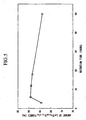
- FIG. 5 is a graph showing the relationship between the amount of La(Fe 0.89 Si 0.11 ) 13 formed and the retention time for heat-treating an RE-containing alloy at a maximum retention temperature of 1,100°C.
- the amount of La(Fe 0.89 Si 0.11 ) 13 formed gradually decreases when the heat treatment time exceeds 12 hours.
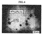
- a conceivable reason for the decrease is that a rare earth element component present in the near surface of the alloy piece is released and evaporated to yield an alloy microstructure as shown in FIG. 6 , which should have desirably yielded a uniform microstructure as shown in FIG. 4 .
- the heat treatment is preferably performed at 1,080 to 1,200°C for 3 to 42 hours. More preferably, the heat treatment is performed at a maximum heat treatment temperature of 1,100 to 1,120°C and a retention time of 6 to 12 hours.
- the RE-containing alloy which has been cast through rapid quenching and has undergone heat treatment (the third RE-containing alloy) assumes the form of flakes, which themselves are not suited for producing a magnetic refrigerant or a magnetostrictive material. Therefore, the flakes are pulverized to form a powder having a mean particle size of 0.1 ⁇ m to 1.0 mm.
- the powder itself or a sintered product obtained by compacting and sintering the powder is employed as a magnetic refrigerant or a mangetostrictive material.
- a powder having a particle size of at least 200 ⁇ m is preferably employed as a magnetic refrigerant without further treatment, whereas a powder having a particle size less than 200 ⁇ m is preferably sintered to provide a magnetostrictive device or a magnetic refrigerant.
- the aforementioned third RE-containing alloy can be pulverized by various mechanical means in accordance with the target mean particle size of the powder; e.g., a jaw crusher (500 ⁇ m or more); a disk mill (50 to 500 ⁇ m); and an attriter or a jet mill employing an inert gas such as nitrogen or argon (50 ⁇ m or less).
- the produced powder is sieved in accordance with need, to thereby form a powder having a desired particle size.
- the shape of the powder can be regulated by controlling the amount of alloy placed in a container of a pulverizer and the pressure of pulverization gas.
- the amount (as determined through powder X-ray diffractometry) of the NaZn 13 structure formed in the aforementioned third RE-containing alloy is less than 85 mass% and ⁇ -Fe content (as determined through powder X-ray diffractometry) is more than 15 mass%, ease of pulverization of the alloy by mechanical means is considerably deteriorated, whereas when the amount of the NaZn 13 structure formed in the alloy is 85 mass% or more, such an alloy is brittle and readily pulverized.
- the third RE-containing alloy is mechanically pulverized, the amount of the NaZn 13 structure formed in the alloy and the ⁇ -Fe content must be controlled to 85 mass% or more and 15 mass% or less, respectively.
- the amount of the NaZn 13 structure formed in the third RE-containing alloy and the ⁇ -Fe content can be controlled by modifying the.composition of the alloy and the cast alloy heating conditions.
- an RE-containing alloy is cast through rapid quenching, followed by further heat treatment at 1,080°C to 1,200°C for 3 to 42 hours, the RE-containing alloy being represented by a compositional formula of R r T t A a (wherein R represents at least one rare earth element selected from among La, Ce, Pr, Nd, Sm, Eu, Tb, Dy, Ho, Tm, Yb, Gd, and Lu; T collectively represents transition metal elements containing at least Fe atoms, a portion of the Fe atoms being optionally substituted by at least one species selected from among Co, Ni, Mn, Pt, and Pd; A represents at least one element selected from among Al
- the mechanical strength of the alloy powder is enhanced by maintaining the amount of ⁇ -Fe contained in particles of the powder at 5 mass% or more, thereby preventing crushing of the powder.
- the third RE-containing alloy powder preferably contains ⁇ -Fe in an amount of 5-15 mass% inclusive.
- the third RE-containing alloy powder is compacted, a compact having sufficient mechanical strength is produced at a compacting pressure of 0.8 t/cm 2 or higher. Such a compact can be used without any problem in a subsequent step, such as conveying. However, when the alloy powder is compacted at a pressure lower than 0.8 t/cm 2 , the produced compact has poor mechanical strength and is difficult to use, because of chipping.
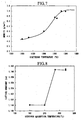
- FIG 7 is a graph showing the relationship between sintering temperature and density of the sintered product, the product having been obtained from an alloy powder having a particle size of 50 to 100 ⁇ m. As is clear from FIG 7 , sintering at 1,280°C or more results in sufficient density of the sintered product.
- a compact produced from La(Fe 0.89 Si 0.11 ) 13 powder (particle size: 50 to 100 ⁇ m) is sintered at 1,280°C for three hours, followed by heating at 1,100°C for 12 hours, to thereby produce sintered La(Fe 0.89 Si 0.11 ) 13 having a density of 6.9 g/cm 3 or more.
- the Curie temperature of the sintered RE-containing alloy can be controlled by absorbing hydrogen into the sintered alloy.
- FIG. 8 is a graph showing the relationship between the absorption temperature and the lattice constant of the sintered RE-containing alloy which has absorbed hydrogen. As shown in FIG. 8 , no change in lattice constant is observed from room temperature to 200°C, indicating that hydrogen absorption does not occur. At 200°C and higher, an increase in lattice constant induced by hydrogen absorption is observed. Accordingly, in order to absorb hydrogen into the sintered alloy, the sintered alloy is preferably maintained in hydrogen at atmospheric pressure for one hour or longer at a maximum temperature of 200 to 300°C, more preferably 230 to 270°C, and cooled in the hydrogen atmosphere. Thus, absorbing hydrogen into the sintered alloy changes the lattice constant, thereby controlling the Curie temperature of the sintered RE-containing alloy.
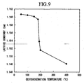
- FIG. 9 is a graph showing change in lattice constant of a sintered alloy which has undergone excessive hydrogen absorption by heating at 400°C in hydrogen at atmospheric pressure, followed by dehydrogenation at various temperatures.
- the lattice constant decreases as the dehydrogenation temperature is elevated. In particular, decrease in lattice constant is remarkable from about 190°C.
- the RE-containing alloy When hydrogen is absorbed into a sintered RE-containing alloy having an ⁇ -Fe content less than 5 mass%, numerous cracks are induced by hydrogen absorption in the sintered alloy, leading to deterioration of mechanical strength, which is not preferred. Therefore, in the case where the Curie temperature of a sintered RE-containing alloy is controlled through hydrogen absorption, the RE-containing alloy preferably contains ⁇ -Fe in the alloy microstructure in an amount of at least 5 mass% so as to maintain mechanical strength of the sintered alloy. In other words, in order to satisfy both pulverization efficiency and mechanical strength of the sintered alloy, the RE-containing alloy preferably contains ⁇ -Fe in an amount of 5-15 mass% inclusive.
- the RE-containing alloy may further contain, other than the NaZn 13 structure and ⁇ -Fe, a second phase in the microstructure.
- the second phase is provided for exerting an effect for enhancing thermal conversion efficiency by increasing the width of a peak attributed to entropy change.
- a plurality of long-term heat treatments which have conventionally been performed, can be omitted, thereby reducing the oxygen concentration.
- a sintered alloy having an oxygen concentration of 5,000 ppm or less can be produced.
- the sintered RE-containing alloy produced as described in the present description is corroded when exposed to the air or to a wet atmosphere. Therefore, in accordance with needs, progress of corrosion can be prevented by coating with resin or metal. Through coating, the oxygen concentration and the nitrogen concentration in the sintered alloy can be suppressed to 5,000 ppm or less.
- the oxygen concentration of alloy powder, sintered alloy, and compacts can be suppressed to a low level.
- rare earth metals serving as starting materials have a purity of about 98 mass%, satisfactory characteristics can be attained.
- the sintered RE-containing alloy produced as disclosed in the present description be employed as a magnetostrictive material for producing a magnetostrictive device.
- the device is produced by winding a coil around the sintered alloy product and works by changing a magnetic field to cause dimensional changes of the sintered alloy product.
- the alloy is employed as a magnetic refrigerant, the alloy is charged, in the form of a plate, porous sintered product, or powder, into a tube through which a cooling medium is passed.
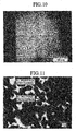
- the molten metal was poured, onto a copper roller which was cooled with water and rotating at a rotating speed of 0.882 m/s, at a pour rate of 150 g/s and a width of 85 mm, to thereby rapidly quench the molten metal, whereby alloy strips having a thickness of 0.28 mm were produced.
- the cooling rate as measured within a range of 1,600 to 900°C was found to be approximately 1 ⁇ 10 3 °C/sec.
- FIGs. 10 and 11 are back-scattered electron images of a cross-section of a sample of the produced alloy strips.
- the image of FIG. 11 is an enlarged image of FIG 10 .
- the alloy strip sample was found to have a minute microstructure in which an R-rich phase (white portion) had a size of 5 ⁇ m or less and an R-poor phase (gray portion) had a size of 10 ⁇ m or less.
- the thus-produced alloy strips were heated at 1,100°C for three hours in a vacuum atmosphere ( ⁇ 5 Pa), followed by pulverization.
- the formed powder was analyzed through powder X-ray diffractometry. Through analysis, a peak attributed to NaZn 13 structure (containing rare earth metals) was observed, confirming that an NaZn 13 phase was formed. Through observation of a back-scattered electron image, the NaZn 13 phase content was found to be 90 vol.% or higher.
- a starting alloy in which an R-rich phase and an R-poor phase are uniformly dispersed at a phase spacing of 0.01 to 100 ⁇ m can be produced.
- an NaZn 13 -type RE-containing alloy having an NaZn 13 phase content of at least 90 vol.% can be produced through heat treatment for a time as short as one minute to 200 hours.
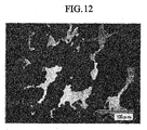
- a molten metal was prepared in a manner similar to that of the Example, and an alloy was produced through the book mold method. Specifically, the molten metal was poured into a mold in which copper plates having a thickness of 20 mm were juxtaposed at intervals of 30 mm, and allowed to stand for three hours for cooling to 50°C.
- FIG. 12 is a back-scattered image of a cross-section of the produced alloy sample.
- the alloy of the Comparative Example 1 produced through the book mold method has a considerably coarse alloy microstructure as compared with that of the alloy of Example 1 produced through rapid quenching.
- the alloy of the Comparative Example includes three or more phases; i.e., an R-rich phase, an R-poor phase, and one or more other phases, with each phase having a size of 100 ⁇ m or more.
- the alloy was heated at 1,100°C for three hours, followed by pulverization.
- the formed powder was analyzed through powder X-ray diffractometry. Through analysis, in addition to a peak attributed to NaZn 13 structure, peaks attributed to ⁇ -Fe and an undesired phases were observed. Through observation of a back-scattered electron image of the alloy for analysis of metallographic microstructure and formed phases, the alloy was found to be formed of multiphases, and the undesired phase was found to remain after heat treatment of 1,100°C for 100 hours. The results indicate that removing the undesired phase present in the alloy requires a long-period heat treatment.
- the thus-produced La-Fe-Si alloy was pulverized by means of a disk mill, and the formed powder was classified by use of a sieve (100 ⁇ m). The pulverization efficiency was found to be 1.2 kg/h. Subsequently, the thus-produced powder was compacted in a nitrogen atmosphere at a compacting pressure of 1.0 t/cm 2 . The compact was sintered in a vacuum at 1,280°C for three hours, followed by heating at 1,100°C for 12 hours, to thereby produce sintered La(Fe 0.89 Si 0.11 ) 13 alloy.
- X-ray diffractometry of the sintered alloy shows that the relative peak intensity of La(Fe 0.89 Si 0.11 ) 13 alloy, having NaZn 13 -type crystal structure, is 93 mass%. Regarding a phase other than La(Fe 0.89 Si 0.11 ) 13 alloy, a peak attributed to ⁇ -Fe (7 mass%) was observed.
- the oxygen concentration and the nitrogen concentration of the sintered alloy were determined to be 2,250 ppm and 80 ppm, respectively.
- the thus-obtained alloy was heated at 1,100°C for 12 hours.
- the heated alloy was found to contain ⁇ -Fe in an amount of 46 mass% and La(Fe 0.89 Si 0.11 ) 13 , having an NaZn 13 structure, in an amount of 54 mass%.
- the thus-produced alloy was pulverized by means of a disk mill, and the formed powder was classified by use of a sieve (100 ⁇ m). Since the alloy has an ⁇ -Fe content in excess of 15 mass%, the pulverization efficiency did not reach 0.2 kg/h.
- the thus-produced powder was compacted in a nitrogen atmosphere at compacting pressure of 1.0 t/cm 2 .
- the compact was sintered in vacuum at 1,280°C for three hours, followed by maintaining at 1,100°C for 12 hours, to thereby produce sintered La(Fe 0.89 Si 0.11 ) 13 .
- the oxygen concentration and the nitrogen concentration of the sintered product were determined to be 6,200 ppm and 130 ppm, respectively.
- the percent volume increase in a magnetic field of a device produced from the alloy was found to be 40% or less based on that of a device produced from the alloy of the Example.
- the thus-produced powder was compacted in a nitrogen atmosphere at compacting pressure of 1.0 t/cm 2 .
- the compact was sintered in vacuum at 1,280°C for three hours, followed by maintaining at 1,100°C for 12 hours, to thereby produce sintered La(Fe 0.89 Si 0.11 ) 13 .
- the sintered product was found to have an La(Fe 0.89 Si 0.11 ) 13 content, as measured from the relative peak intensity of La(Fe 0.89 Si 0.11 ) 13 , of 99 mass%. Regarding a phase other than La(Fe 0.89 Si 0.11 ) 13 , 1 mass% of ⁇ -Fe was determined from the peak intensity of ⁇ -Fe.
- the RE-containing alloy obtained according to the method of the present invention can be utilized to produce a magnetstrictive device and a magnetic refrigerant, and thus has industrial applicability.
Landscapes
- Engineering & Computer Science (AREA)
- Chemical & Material Sciences (AREA)
- Mechanical Engineering (AREA)
- Power Engineering (AREA)
- Materials Engineering (AREA)
- Metallurgy (AREA)
- Organic Chemistry (AREA)
- Crystallography & Structural Chemistry (AREA)
- Thermal Sciences (AREA)
- Physics & Mathematics (AREA)
- Manufacturing & Machinery (AREA)
- Inorganic Chemistry (AREA)
- Manufacture Of Metal Powder And Suspensions Thereof (AREA)
- Powder Metallurgy (AREA)
- Hard Magnetic Materials (AREA)
Claims (7)
- Verfahren zur Herstellung einer Seltene Erden enthaltenden Legierung der Formel R (T1-xAx)13-y, worin R mindestens ein Element darstellt, welches aus La, Ce, Pr, Nd, Sm, Eu, Tb, Dy, Ho, Tm, Yb, Gd und Lu ausgewählt ist; T mindestens ein Element ist, welches aus Fe, Co, Ni, Mn, Pt und Pd ausgewählt ist; und A mindestens ein Element ist, welches aus Al, As, Si, Ga, Ge, Mn, Sn und Sb ausgewählt ist; wobei 0.05 ≤ x ≤ 0,2 und -1 ≤ y ≤ 1; umfassend einen Schmelzschritt, bei dem Legierungsrohmaterialien bei 1200 bis 1800°C geschmolzen werden; und einen Verfestigungsschritt, bei dem das bei dem obigen Schritt erzeugte geschmolzene Metall schnell abgekühlt wird, um so eine erste Seltene Erden enthaltende Legierung zu bilden, wobei der Verfestigungsschritt bei einer Kühlrate von 102 bis 104 °C/Sekunde durchgeführt wird, gemessen zumindest in einem Bereich von der Temperatur des geschmolzenen Metalls bis 900°C.
- Verfahren zur Herstellung einer Seltene Erden enthaltenden Legierung nach Anspruch 1, worin in dem Schmelzschritt das Legierungsrohmaterial in einer Intertgasatmosphäre bei 0,1 bis 0,2 MPa geschmolzen wird.
- Verfahren zur Herstellung der ersten Seltene Erden enthaltenden Legierung nach Anspruch 1, worin in dem Verfestigungsschritt das geschmolzene Metall schnell abgekühlt wird, indem die Kühlrate von dem geschmolzenen Zustand bis 900°C mittels Bandgießen oder Schwerkraftgießen gesteuert wird.
- Verfahren zur Herstellung der Seltene Erden enthaltenden Legierung nach Anspruch 3, worin das geschmolzene Metall in dem Verfestigungsschritt schnell mittels Bandgießen abgekühlt wird, um Bänder mit einer Dicke von 0,1 bis 2,0 mm zu erhalten.
- Verfahren zur Herstellung einer Seltene Erden enthaltenden Legierung, umfassend einen Schmelzschritt und einen Verfestigungsschritt zur Erzeugung der Seltene Erden enthaltenden Legierung nach Anspruch 1, sowie einen Wärmebehandlungsschritt, bei dem bei 900 bis 1200° die Seltene Erden enthaltende Legierung, welche durch den Verfestigungsschritt erzeugt wurde, erhitzt wird, um so eine NaZn13-Phase zu bilden.
- Verfahren zur Herstellung einer Seltene Erden enthaltenden Legierung nach Anspruch 5, worin die NaZn13-Phase mittels des Wärmebehandlungsschritts gebildet wird, welcher für einen Zeitraum von einer Minute bis 200 Stunden durchgeführt wird.
- Verfahren zur Herstellung einer Seltene Erden enthaltenden Legierung nach Anspruch 6, wobei die Wärmebehandlung bei einer Temperatur von 1080°C bis 1200°C und für einen Zeitraum von 3 bis 42 Stunden durchgeführt wird.
Applications Claiming Priority (9)
| Application Number | Priority Date | Filing Date | Title |
|---|---|---|---|
| JP2002311213 | 2002-10-25 | ||
| JP2002311213 | 2002-10-25 | ||
| US42401502P | 2002-11-06 | 2002-11-06 | |
| US424015P | 2002-11-06 | ||
| JP2003181364 | 2003-06-25 | ||
| JP2003181364 | 2003-06-25 | ||
| US48809503P | 2003-07-18 | 2003-07-18 | |
| US488095P | 2003-07-18 | ||
| PCT/JP2003/013494 WO2004038055A1 (en) | 2002-10-25 | 2003-10-22 | Alloy containing rare earth element, production method thereof, magnetostrictive device, and magnetic refrigerant material |
Publications (3)
| Publication Number | Publication Date |
|---|---|
| EP1554411A1 EP1554411A1 (de) | 2005-07-20 |
| EP1554411A4 EP1554411A4 (de) | 2006-08-23 |
| EP1554411B1 true EP1554411B1 (de) | 2013-05-08 |
Family
ID=32180620
Family Applications (1)
| Application Number | Title | Priority Date | Filing Date |
|---|---|---|---|
| EP03809445.4A Expired - Lifetime EP1554411B1 (de) | 2002-10-25 | 2003-10-22 | Herstellungsverfahren einer seltenerdelement enthaltende legierung |
Country Status (5)
| Country | Link |
|---|---|
| US (2) | US7695574B2 (de) |
| EP (1) | EP1554411B1 (de) |
| CN (1) | CN1705761B (de) |
| AU (1) | AU2003301577A1 (de) |
| WO (1) | WO2004038055A1 (de) |
Cited By (2)
| Publication number | Priority date | Publication date | Assignee | Title |
|---|---|---|---|---|
| CN107052286A (zh) * | 2017-04-01 | 2017-08-18 | 昆明理工大学 | 一种铝锡轴瓦合金的制备方法 |
| CN107876753A (zh) * | 2017-11-29 | 2018-04-06 | 北京科技大学 | 一种动铁单元用磁轭及其制备方法 |
Families Citing this family (42)
| Publication number | Priority date | Publication date | Assignee | Title |
|---|---|---|---|---|
| JP4413804B2 (ja) | 2005-03-24 | 2010-02-10 | 株式会社東芝 | 磁気冷凍材料及びその製造方法 |
| US7578892B2 (en) | 2005-03-31 | 2009-08-25 | Hitachi Metals, Ltd. | Magnetic alloy material and method of making the magnetic alloy material |
| GB2424901B (en) * | 2005-04-01 | 2011-11-09 | Neomax Co Ltd | Method of making a sintered body of a magnetic alloyl |
| WO2006107042A1 (ja) | 2005-04-05 | 2006-10-12 | Hitachi Metals, Ltd. | 磁性合金及びその製造方法 |
| JP4750471B2 (ja) * | 2005-05-26 | 2011-08-17 | 株式会社豊田中央研究所 | 低磁歪体及びこれを用いた圧粉磁芯 |
| CN101233632B (zh) * | 2005-08-02 | 2010-11-24 | 昭和电工株式会社 | 用于锂二次电池负极的合金 |
| GB0519843D0 (en) | 2005-09-29 | 2005-11-09 | Univ Cambridge Tech | Magnetocaloric refrigerant |
| JP2010516042A (ja) * | 2007-02-12 | 2010-05-13 | ヴァキュームシュメルツェ ゲーエムベーハー ウント コンパニー カーゲー | 磁気熱交換用構造体及びその製造方法 |
| JP5582784B2 (ja) * | 2007-02-12 | 2014-09-03 | ヴァキュームシュメルツェ ゲーエムベーハー ウント コンパニー カーゲー | 磁気熱交換用構造体及びその製造方法 |
| CN100463083C (zh) * | 2007-04-24 | 2009-02-18 | 包头稀土研究院 | 一种FeGa-RE系磁致伸缩材料及其制造工艺 |
| JP2009068077A (ja) * | 2007-09-13 | 2009-04-02 | Tohoku Univ | 合金材料、磁性材料、磁性材料の製造方法およびその製造方法により製造した磁性材料 |
| EP2071593A1 (de) * | 2007-12-14 | 2009-06-17 | Imphy Alloys | Fe-Si-La-Legierung mit ausgezeichneten magneto-kalorischen Eigenschaften |
| JP2010525291A (ja) * | 2007-12-27 | 2010-07-22 | ヴァキュームシュメルツェ ゲーエムベーハー ウント コンパニー カーゲー | 磁気熱量活性物質を有する複合構造体及びその製造方法 |
| US20110061775A1 (en) * | 2008-04-28 | 2011-03-17 | Technology Foundation Stw | Method for producing metal-based materials for magnetic cooling or heat pumps |
| GB2461400B (en) * | 2008-05-16 | 2012-11-21 | Vacuumschmelze Gmbh & Co Kg | Article for magnetic heat exchange |
| WO2010003926A1 (en) * | 2008-07-08 | 2010-01-14 | Technical University Of Denmark | Magnetocaloric refrigerators |
| KR101233462B1 (ko) * | 2008-10-01 | 2013-02-14 | 바쿰슈멜체 게엠베하 운트 코. 카게 | 적어도 하나의 자기열량적 활성상을 포함하는 물품 및 적어도 하나의 자기열량적 활성상을 포함하는 물품의 가공 방법 |
| WO2010038099A1 (en) * | 2008-10-01 | 2010-04-08 | Vacuumschmelze Gmbh & Co. Kg | Article for use in magnetic heat exchange, intermediate article and method for producing an article for use in magnetic heat exchange |
| GB2463931B (en) * | 2008-10-01 | 2011-01-12 | Vacuumschmelze Gmbh & Co Kg | Method for producing a magnetic article |
| DE102008054522B4 (de) | 2008-12-11 | 2013-11-21 | Leibniz-Institut Für Festkörper- Und Werkstoffforschung Dresden E.V. | Verfahren zur Beschichtung der Oberflächeeines magnetischen Legierungsmaterials sowie ein solches Legierungsmaterial |
| DE102009002640A1 (de) | 2009-04-24 | 2011-01-20 | Leibniz-Institut Für Festkörper- Und Werkstoffforschung Dresden E.V. | Magnetisches Legierungsmaterial und Verfahren zu seiner Herstellung |
| GB2475985B (en) | 2009-05-06 | 2012-03-21 | Vacuumschmelze Gmbh & Co Kg | Article for magnetic heat exchange and method of fabricating an article for magnetic heat exchange |
| US9895748B2 (en) * | 2009-10-14 | 2018-02-20 | Vacuumschmelze & Gmbh & Co. Kg | Article for magnetic heat exchange and method of manufacturing the same |
| GB2482880B (en) | 2010-08-18 | 2014-01-29 | Vacuumschmelze Gmbh & Co Kg | An article for magnetic heat exchange and a method of fabricating a working component for magnetic heat exchange |
| CN102703037B (zh) * | 2011-03-28 | 2015-05-27 | 中国科学院物理研究所 | 用于磁制冷的稀土-铁-硅材料及其制备方法和用途 |
| US20140166159A1 (en) * | 2011-07-14 | 2014-06-19 | Hubei Quanyang Magnetic Materials Manufacturing Co., Ltd | La(fe,si)13-based magnetic refrigeration material prepared from industrial-pure mischmetal as the raw material and preparation and use thereof |
| JP5565394B2 (ja) * | 2011-09-14 | 2014-08-06 | 株式会社デンソー | 磁気冷凍材料および磁気冷凍材料の製造方法 |
| CN103137281B (zh) * | 2011-11-22 | 2016-06-01 | 中国科学院物理研究所 | 粘结La(Fe,Si)13基磁热效应材料及其制备方法和用途 |
| US20150239048A1 (en) * | 2012-09-12 | 2015-08-27 | Xiamen Tungsten Co., Ltd. | Manufacturing method of rare earth magnet alloy powder, rare earth magnet and a powder making device |
| CN103710605B (zh) * | 2012-09-28 | 2016-06-29 | 中国科学院物理研究所 | 一种具有大熵变的MnCoGe基铁磁马氏体相变材料及制备方法和用途 |
| JP2014087812A (ja) * | 2012-10-29 | 2014-05-15 | Toyota Motor Corp | 希土類磁石合金薄帯の製造方法 |
| US9568223B2 (en) | 2013-10-25 | 2017-02-14 | The Johns Hopkins University | Magnetocaloric materials for cryogenic liquification |
| CN103647019B (zh) * | 2013-11-27 | 2016-08-17 | 南京航空航天大学 | 一种轻稀土调制的巨磁致伸缩材料及其制备工艺 |
| CN104775068B (zh) * | 2015-04-02 | 2017-01-11 | 浙江大学 | 一种高性能宏观泡沫态Fe73Ga27磁致伸缩材料及其制备工艺 |
| JP2017110262A (ja) * | 2015-12-16 | 2017-06-22 | トヨタ自動車株式会社 | 断熱材料及びその製造方法 |
| CN107537990A (zh) * | 2017-07-05 | 2018-01-05 | 上海大学 | 一种La–Fe–Si系薄板材的快速液态成型方法 |
| CN111254338B (zh) * | 2020-01-21 | 2021-06-01 | 西华大学 | 一种磁致伸缩材料及其制备方法 |
| CN112575270B (zh) * | 2020-11-20 | 2022-04-26 | 东南大学 | 一种氢化重稀土高熵复合材料及其制备方法和应用 |
| CN112844537B (zh) * | 2021-01-11 | 2022-03-29 | 东阳市安瑞磁业有限公司 | 磁性材料加工系统及方法 |
| CN113546746B (zh) * | 2021-07-26 | 2022-12-06 | 广州城建职业学院 | 一种建筑垃圾粉碎装置 |
| CN114192790B (zh) * | 2021-11-29 | 2024-01-23 | 成都先进金属材料产业技术研究院股份有限公司 | 球形钛及钛合金粉末制备装置和方法 |
| CN116532643B (zh) * | 2023-04-11 | 2026-01-30 | 东南大学 | 一种氢化重稀土基非晶合金粉末材料及其制法 |
Family Cites Families (22)
| Publication number | Priority date | Publication date | Assignee | Title |
|---|---|---|---|---|
| NL8300465A (nl) | 1983-02-08 | 1984-09-03 | Philips Nv | Invar-legering op ijzer-basis met een kristalstructuur van het nazn13 type en werkwijze voor het produceren daarvan. |
| JPS6017905A (ja) | 1983-07-08 | 1985-01-29 | Sumitomo Special Metals Co Ltd | 永久磁石用合金粉末 |
| JPH01246342A (ja) | 1988-03-29 | 1989-10-02 | Daido Steel Co Ltd | 超磁歪材料とその製造方法 |
| JPH0268904A (ja) | 1988-09-05 | 1990-03-08 | Kobe Steel Ltd | 希土類−Fe−B系ボンド磁石用合金粉末の製造方法 |
| CN1025125C (zh) * | 1992-05-07 | 1994-06-22 | 冶金工业部钢铁研究总院 | 铁-稀土基磁致冷材料及制备方法 |
| JP2837790B2 (ja) | 1993-05-11 | 1998-12-16 | 山陽特殊製鋼株式会社 | 低酸素希土類合金アトマイズ粉末およびその製造方法 |
| JP3411663B2 (ja) | 1994-03-18 | 2003-06-03 | 住友特殊金属株式会社 | 永久磁石合金並びに永久磁石合金粉末とその製造方法 |
| JP3466481B2 (ja) | 1998-07-31 | 2003-11-10 | 和明 深道 | 超磁歪材料 |
| JP2000129304A (ja) | 1998-10-23 | 2000-05-09 | Sumitomo Metal Mining Co Ltd | R−Fe−B系焼結磁石用原料合金粉末 |
| US7011718B2 (en) * | 2001-04-25 | 2006-03-14 | Metglas, Inc. | Bulk stamped amorphous metal magnetic component |
| JP2002064009A (ja) | 2000-08-22 | 2002-02-28 | Sumitomo Special Metals Co Ltd | 鉄基希土類合金磁石およびその製造方法 |
| JP4471249B2 (ja) * | 2000-09-05 | 2010-06-02 | 和明 深道 | 磁性体 |
| EP1626418A3 (de) * | 2000-09-08 | 2007-11-07 | Shin-Etsu Chemical Co., Ltd. | Seltenerd-Legierung, Seltenerd-Sintermagnet und Herstellungsverfahren |
| JP2002161302A (ja) | 2000-09-18 | 2002-06-04 | Sumitomo Special Metals Co Ltd | 永久磁石用磁性合金粉末およびその製造方法 |
| WO2002030595A1 (en) * | 2000-10-06 | 2002-04-18 | Santoku Corporation | Process for producing, through strip casting, raw alloy for nanocomposite type permanent magnet |
| JP3715582B2 (ja) * | 2001-03-27 | 2005-11-09 | 株式会社東芝 | 磁性材料 |
| US7014718B2 (en) * | 2001-09-03 | 2006-03-21 | Showa Denko K.K. | Rare earth magnet alloy ingot, manufacturing method for the same, R-T-B type magnet alloy ingot, R-T-B type magnet, R-T-B type bonded magnet, R-T-B type exchange spring magnet alloy ingot, R-T-B type exchange spring magnet, and R-T-B type exchange spring bonded magnet |
| JP3967572B2 (ja) | 2001-09-21 | 2007-08-29 | 株式会社東芝 | 磁気冷凍材料 |
| US6653561B2 (en) | 2001-09-25 | 2003-11-25 | Thomas & Betts International, Inc. | Outlet box and partition |
| JP3630164B2 (ja) | 2002-08-21 | 2005-03-16 | 株式会社Neomax | 磁性合金材料およびその製造方法 |
| US7186303B2 (en) | 2002-08-21 | 2007-03-06 | Neomax Co., Ltd. | Magnetic alloy material and method of making the magnetic alloy material |
| JP4413804B2 (ja) | 2005-03-24 | 2010-02-10 | 株式会社東芝 | 磁気冷凍材料及びその製造方法 |
-
2003
- 2003-10-22 CN CN2003801018182A patent/CN1705761B/zh not_active Expired - Fee Related
- 2003-10-22 EP EP03809445.4A patent/EP1554411B1/de not_active Expired - Lifetime
- 2003-10-22 WO PCT/JP2003/013494 patent/WO2004038055A1/en not_active Ceased
- 2003-10-22 AU AU2003301577A patent/AU2003301577A1/en not_active Abandoned
- 2003-10-22 US US10/531,480 patent/US7695574B2/en not_active Expired - Fee Related
-
2010
- 2010-02-17 US US12/707,569 patent/US8110049B2/en not_active Expired - Fee Related
Cited By (2)
| Publication number | Priority date | Publication date | Assignee | Title |
|---|---|---|---|---|
| CN107052286A (zh) * | 2017-04-01 | 2017-08-18 | 昆明理工大学 | 一种铝锡轴瓦合金的制备方法 |
| CN107876753A (zh) * | 2017-11-29 | 2018-04-06 | 北京科技大学 | 一种动铁单元用磁轭及其制备方法 |
Also Published As
| Publication number | Publication date |
|---|---|
| AU2003301577A1 (en) | 2004-05-13 |
| CN1705761A (zh) | 2005-12-07 |
| US7695574B2 (en) | 2010-04-13 |
| CN1705761B (zh) | 2010-05-12 |
| US20100143178A1 (en) | 2010-06-10 |
| EP1554411A4 (de) | 2006-08-23 |
| WO2004038055A1 (en) | 2004-05-06 |
| US20060076084A1 (en) | 2006-04-13 |
| US8110049B2 (en) | 2012-02-07 |
| EP1554411A1 (de) | 2005-07-20 |
| WO2004038055A9 (en) | 2004-07-08 |
Similar Documents
| Publication | Publication Date | Title |
|---|---|---|
| EP1554411B1 (de) | Herstellungsverfahren einer seltenerdelement enthaltende legierung | |
| RU2113742C1 (ru) | Материалы r-fe-b постоянных магнитов и способы их получения | |
| US5963774A (en) | Method for producing cast alloy and magnet | |
| US5666635A (en) | Fabrication methods for R-Fe-B permanent magnets | |
| US7833361B2 (en) | Alloy and method for producing magnetic refrigeration material particles using same | |
| US7670443B2 (en) | Magnetic alloy material and method of making the magnetic alloy material | |
| TWI402359B (zh) | 具有優良磁卡路里性質的Fe-Si-La合金 | |
| CA1269029A (en) | Permanent magnet manufacture from very low coercivity crystalline rare earth-transition metal-boron alloy | |
| JP6561117B2 (ja) | 希土類永久磁石およびその製造方法 | |
| JP2005036302A (ja) | 希土類含有合金の製造方法、希土類含有合金、希土類含有合金粉末の製造方法、希土類含有合金粉末、希土類含有合金焼結体の製造方法、希土類含有合金焼結体、磁歪素子、及び磁気冷凍作業物質 | |
| JP2004100043A (ja) | 磁性合金材料およびその製造方法 | |
| CN101541999A (zh) | R-t-b系合金和r-t-b系合金的制造方法、r-t-b系稀土类永久磁铁用微粉、r-t-b系稀土类永久磁铁 | |
| JP3505261B2 (ja) | Sm−Co系永久磁石材料、永久磁石及びその製造法 | |
| JP5157076B2 (ja) | 磁性合金の焼結体の製造方法 | |
| JP6760538B2 (ja) | 希土類磁石粉末の製造方法 | |
| US7338566B2 (en) | Alloy for sm-co based magnet, method for production thereof, sintered magnet and bonded magnet | |
| JP4371040B2 (ja) | 磁性合金材料およびその製造方法 | |
| JP3474684B2 (ja) | 耐食性のすぐれた高性能R−Fe−B−C系磁石材料 | |
| JP2004143595A (ja) | 希土類磁石用原料合金、その製造方法及び希土類磁石用合金粉末 | |
| JP2005200749A (ja) | 磁性薄片およびその製造方法 | |
| JPH0745412A (ja) | R−Fe−B系永久磁石材料 | |
| CN119495482A (zh) | 钕铁硼速凝铸片、钕铁硼磁粉及制备方法 | |
| JP4133315B2 (ja) | 希土類磁石の製造法、希土類磁石用原料合金及び粉末 | |
| JPS5886706A (ja) | 永久磁石の製造方法 |
Legal Events
| Date | Code | Title | Description |
|---|---|---|---|
| PUAI | Public reference made under article 153(3) epc to a published international application that has entered the european phase |
Free format text: ORIGINAL CODE: 0009012 |
|
| 17P | Request for examination filed |
Effective date: 20050511 |
|
| AK | Designated contracting states |
Kind code of ref document: A1 Designated state(s): AT BE BG CH CY CZ DE DK EE ES FI FR GB GR HU IE IT LI LU MC NL PT RO SE SI SK TR |
|
| AX | Request for extension of the european patent |
Extension state: AL LT LV MK |
|
| DAX | Request for extension of the european patent (deleted) | ||
| A4 | Supplementary search report drawn up and despatched |
Effective date: 20060721 |
|
| 17Q | First examination report despatched |
Effective date: 20061013 |
|
| RTI1 | Title (correction) |
Free format text: PRODUCTION METHOD OF AN ALLOY CONTAINING RARE EARTH ELEMENT |
|
| GRAP | Despatch of communication of intention to grant a patent |
Free format text: ORIGINAL CODE: EPIDOSNIGR1 |
|
| TPAC | Observations filed by third parties |
Free format text: ORIGINAL CODE: EPIDOSNTIPA |
|
| GRAS | Grant fee paid |
Free format text: ORIGINAL CODE: EPIDOSNIGR3 |
|
| GRAA | (expected) grant |
Free format text: ORIGINAL CODE: 0009210 |
|
| AK | Designated contracting states |
Kind code of ref document: B1 Designated state(s): AT BE BG CH CY CZ DE DK EE ES FI FR GB GR HU IE IT LI LU MC NL PT RO SE SI SK TR |
|
| REG | Reference to a national code |
Ref country code: GB Ref legal event code: FG4D |
|
| REG | Reference to a national code |
Ref country code: AT Ref legal event code: REF Ref document number: 611151 Country of ref document: AT Kind code of ref document: T Effective date: 20130515 Ref country code: CH Ref legal event code: EP |
|
| REG | Reference to a national code |
Ref country code: SE Ref legal event code: TRGR |
|
| REG | Reference to a national code |
Ref country code: IE Ref legal event code: FG4D |
|
| REG | Reference to a national code |
Ref country code: DE Ref legal event code: R096 Ref document number: 60344014 Country of ref document: DE Effective date: 20130704 |
|
| REG | Reference to a national code |
Ref country code: AT Ref legal event code: MK05 Ref document number: 611151 Country of ref document: AT Kind code of ref document: T Effective date: 20130508 |
|
| REG | Reference to a national code |
Ref country code: NL Ref legal event code: VDEP Effective date: 20130508 |
|
| PG25 | Lapsed in a contracting state [announced via postgrant information from national office to epo] |
Ref country code: SI Free format text: LAPSE BECAUSE OF FAILURE TO SUBMIT A TRANSLATION OF THE DESCRIPTION OR TO PAY THE FEE WITHIN THE PRESCRIBED TIME-LIMIT Effective date: 20130508 Ref country code: GR Free format text: LAPSE BECAUSE OF FAILURE TO SUBMIT A TRANSLATION OF THE DESCRIPTION OR TO PAY THE FEE WITHIN THE PRESCRIBED TIME-LIMIT Effective date: 20130809 Ref country code: ES Free format text: LAPSE BECAUSE OF FAILURE TO SUBMIT A TRANSLATION OF THE DESCRIPTION OR TO PAY THE FEE WITHIN THE PRESCRIBED TIME-LIMIT Effective date: 20130819 Ref country code: PT Free format text: LAPSE BECAUSE OF FAILURE TO SUBMIT A TRANSLATION OF THE DESCRIPTION OR TO PAY THE FEE WITHIN THE PRESCRIBED TIME-LIMIT Effective date: 20130909 Ref country code: FI Free format text: LAPSE BECAUSE OF FAILURE TO SUBMIT A TRANSLATION OF THE DESCRIPTION OR TO PAY THE FEE WITHIN THE PRESCRIBED TIME-LIMIT Effective date: 20130508 Ref country code: AT Free format text: LAPSE BECAUSE OF FAILURE TO SUBMIT A TRANSLATION OF THE DESCRIPTION OR TO PAY THE FEE WITHIN THE PRESCRIBED TIME-LIMIT Effective date: 20130508 |
|
| PG25 | Lapsed in a contracting state [announced via postgrant information from national office to epo] |
Ref country code: BG Free format text: LAPSE BECAUSE OF FAILURE TO SUBMIT A TRANSLATION OF THE DESCRIPTION OR TO PAY THE FEE WITHIN THE PRESCRIBED TIME-LIMIT Effective date: 20130808 Ref country code: CY Free format text: LAPSE BECAUSE OF FAILURE TO SUBMIT A TRANSLATION OF THE DESCRIPTION OR TO PAY THE FEE WITHIN THE PRESCRIBED TIME-LIMIT Effective date: 20130508 |
|
| REG | Reference to a national code |
Ref country code: DE Ref legal event code: R082 Ref document number: 60344014 Country of ref document: DE Representative=s name: PATENTANWAELTE STREHL, SCHUEBEL-HOPF & PARTNER, DE |
|
| PG25 | Lapsed in a contracting state [announced via postgrant information from national office to epo] |
Ref country code: BE Free format text: LAPSE BECAUSE OF FAILURE TO SUBMIT A TRANSLATION OF THE DESCRIPTION OR TO PAY THE FEE WITHIN THE PRESCRIBED TIME-LIMIT Effective date: 20130508 Ref country code: DK Free format text: LAPSE BECAUSE OF FAILURE TO SUBMIT A TRANSLATION OF THE DESCRIPTION OR TO PAY THE FEE WITHIN THE PRESCRIBED TIME-LIMIT Effective date: 20130508 Ref country code: CZ Free format text: LAPSE BECAUSE OF FAILURE TO SUBMIT A TRANSLATION OF THE DESCRIPTION OR TO PAY THE FEE WITHIN THE PRESCRIBED TIME-LIMIT Effective date: 20130508 Ref country code: EE Free format text: LAPSE BECAUSE OF FAILURE TO SUBMIT A TRANSLATION OF THE DESCRIPTION OR TO PAY THE FEE WITHIN THE PRESCRIBED TIME-LIMIT Effective date: 20130508 Ref country code: SK Free format text: LAPSE BECAUSE OF FAILURE TO SUBMIT A TRANSLATION OF THE DESCRIPTION OR TO PAY THE FEE WITHIN THE PRESCRIBED TIME-LIMIT Effective date: 20130508 |
|
| REG | Reference to a national code |
Ref country code: DE Ref legal event code: R082 Ref document number: 60344014 Country of ref document: DE Representative=s name: PATENTANWAELTE STREHL, SCHUEBEL-HOPF & PARTNER, DE Effective date: 20140120 Ref country code: DE Ref legal event code: R081 Ref document number: 60344014 Country of ref document: DE Owner name: ERASTEEL, FR Free format text: FORMER OWNER: SHOWA DENKO K.K., TOKIO/TOKYO, JP Effective date: 20140120 Ref country code: DE Ref legal event code: R081 Ref document number: 60344014 Country of ref document: DE Owner name: ERASTEEL, FR Free format text: FORMER OWNER: SHOWA DENKO K.K., TOKIO/TOKYO, JP Effective date: 20130513 Ref country code: DE Ref legal event code: R082 Ref document number: 60344014 Country of ref document: DE Representative=s name: STREHL SCHUEBEL-HOPF & PARTNER MBB PATENTANWAE, DE Effective date: 20140120 |
|
| PG25 | Lapsed in a contracting state [announced via postgrant information from national office to epo] |
Ref country code: IT Free format text: LAPSE BECAUSE OF FAILURE TO SUBMIT A TRANSLATION OF THE DESCRIPTION OR TO PAY THE FEE WITHIN THE PRESCRIBED TIME-LIMIT Effective date: 20130508 Ref country code: NL Free format text: LAPSE BECAUSE OF FAILURE TO SUBMIT A TRANSLATION OF THE DESCRIPTION OR TO PAY THE FEE WITHIN THE PRESCRIBED TIME-LIMIT Effective date: 20130508 Ref country code: RO Free format text: LAPSE BECAUSE OF FAILURE TO SUBMIT A TRANSLATION OF THE DESCRIPTION OR TO PAY THE FEE WITHIN THE PRESCRIBED TIME-LIMIT Effective date: 20130508 |
|
| REG | Reference to a national code |
Ref country code: FR Ref legal event code: TP Owner name: ERASTEEL, FR Effective date: 20140131 |
|
| PLBE | No opposition filed within time limit |
Free format text: ORIGINAL CODE: 0009261 |
|
| STAA | Information on the status of an ep patent application or granted ep patent |
Free format text: STATUS: NO OPPOSITION FILED WITHIN TIME LIMIT |
|
| RAP2 | Party data changed (patent owner data changed or rights of a patent transferred) |
Owner name: ERASTEEL |
|
| 26N | No opposition filed |
Effective date: 20140211 |
|
| REG | Reference to a national code |
Ref country code: DE Ref legal event code: R097 Ref document number: 60344014 Country of ref document: DE Effective date: 20140211 |
|
| PG25 | Lapsed in a contracting state [announced via postgrant information from national office to epo] |
Ref country code: MC Free format text: LAPSE BECAUSE OF FAILURE TO SUBMIT A TRANSLATION OF THE DESCRIPTION OR TO PAY THE FEE WITHIN THE PRESCRIBED TIME-LIMIT Effective date: 20130508 |
|
| REG | Reference to a national code |
Ref country code: CH Ref legal event code: PL |
|
| GBPC | Gb: european patent ceased through non-payment of renewal fee |
Effective date: 20131022 |
|
| REG | Reference to a national code |
Ref country code: IE Ref legal event code: MM4A |
|
| PG25 | Lapsed in a contracting state [announced via postgrant information from national office to epo] |
Ref country code: GB Free format text: LAPSE BECAUSE OF NON-PAYMENT OF DUE FEES Effective date: 20131022 Ref country code: CH Free format text: LAPSE BECAUSE OF NON-PAYMENT OF DUE FEES Effective date: 20131031 Ref country code: LI Free format text: LAPSE BECAUSE OF NON-PAYMENT OF DUE FEES Effective date: 20131031 |
|
| PG25 | Lapsed in a contracting state [announced via postgrant information from national office to epo] |
Ref country code: IE Free format text: LAPSE BECAUSE OF NON-PAYMENT OF DUE FEES Effective date: 20131022 |
|
| PG25 | Lapsed in a contracting state [announced via postgrant information from national office to epo] |
Ref country code: TR Free format text: LAPSE BECAUSE OF FAILURE TO SUBMIT A TRANSLATION OF THE DESCRIPTION OR TO PAY THE FEE WITHIN THE PRESCRIBED TIME-LIMIT Effective date: 20130508 |
|
| PG25 | Lapsed in a contracting state [announced via postgrant information from national office to epo] |
Ref country code: LU Free format text: LAPSE BECAUSE OF NON-PAYMENT OF DUE FEES Effective date: 20131022 Ref country code: HU Free format text: LAPSE BECAUSE OF FAILURE TO SUBMIT A TRANSLATION OF THE DESCRIPTION OR TO PAY THE FEE WITHIN THE PRESCRIBED TIME-LIMIT; INVALID AB INITIO Effective date: 20031022 |
|
| REG | Reference to a national code |
Ref country code: FR Ref legal event code: PLFP Year of fee payment: 13 |
|
| REG | Reference to a national code |
Ref country code: FR Ref legal event code: PLFP Year of fee payment: 14 |
|
| REG | Reference to a national code |
Ref country code: FR Ref legal event code: PLFP Year of fee payment: 15 |
|
| REG | Reference to a national code |
Ref country code: FR Ref legal event code: PLFP Year of fee payment: 16 |
|
| PGFP | Annual fee paid to national office [announced via postgrant information from national office to epo] |
Ref country code: SE Payment date: 20201028 Year of fee payment: 18 Ref country code: DE Payment date: 20201022 Year of fee payment: 18 Ref country code: FR Payment date: 20201021 Year of fee payment: 18 |
|
| REG | Reference to a national code |
Ref country code: DE Ref legal event code: R119 Ref document number: 60344014 Country of ref document: DE |
|
| REG | Reference to a national code |
Ref country code: SE Ref legal event code: EUG |
|
| PG25 | Lapsed in a contracting state [announced via postgrant information from national office to epo] |
Ref country code: SE Free format text: LAPSE BECAUSE OF NON-PAYMENT OF DUE FEES Effective date: 20211023 Ref country code: DE Free format text: LAPSE BECAUSE OF NON-PAYMENT OF DUE FEES Effective date: 20220503 |
|
| PG25 | Lapsed in a contracting state [announced via postgrant information from national office to epo] |
Ref country code: FR Free format text: LAPSE BECAUSE OF NON-PAYMENT OF DUE FEES Effective date: 20211031 |