EP1554473B1 - Abgasnachbehandlungsanordnung - Google Patents
Abgasnachbehandlungsanordnung Download PDFInfo
- Publication number
- EP1554473B1 EP1554473B1 EP03808663A EP03808663A EP1554473B1 EP 1554473 B1 EP1554473 B1 EP 1554473B1 EP 03808663 A EP03808663 A EP 03808663A EP 03808663 A EP03808663 A EP 03808663A EP 1554473 B1 EP1554473 B1 EP 1554473B1
- Authority
- EP
- European Patent Office
- Prior art keywords
- filter
- flow
- treatment arrangement
- delimiting
- arrangement according
- Prior art date
- Legal status (The legal status is an assumption and is not a legal conclusion. Google has not performed a legal analysis and makes no representation as to the accuracy of the status listed.)
- Expired - Lifetime
Links
Images

Classifications
-
- F—MECHANICAL ENGINEERING; LIGHTING; HEATING; WEAPONS; BLASTING
- F01—MACHINES OR ENGINES IN GENERAL; ENGINE PLANTS IN GENERAL; STEAM ENGINES
- F01N—GAS-FLOW SILENCERS OR EXHAUST APPARATUS FOR MACHINES OR ENGINES IN GENERAL; GAS-FLOW SILENCERS OR EXHAUST APPARATUS FOR INTERNAL-COMBUSTION ENGINES
- F01N3/00—Exhaust or silencing apparatus having means for purifying, rendering innocuous, or otherwise treating exhaust
- F01N3/02—Exhaust or silencing apparatus having means for purifying, rendering innocuous, or otherwise treating exhaust for cooling, or for removing solid constituents of, exhaust
- F01N3/021—Exhaust or silencing apparatus having means for purifying, rendering innocuous, or otherwise treating exhaust for cooling, or for removing solid constituents of, exhaust by means of filters
- F01N3/022—Exhaust or silencing apparatus having means for purifying, rendering innocuous, or otherwise treating exhaust for cooling, or for removing solid constituents of, exhaust by means of filters characterised by specially adapted filtering structure, e.g. honeycomb, mesh or fibrous
-
- B—PERFORMING OPERATIONS; TRANSPORTING
- B01—PHYSICAL OR CHEMICAL PROCESSES OR APPARATUS IN GENERAL
- B01D—SEPARATION
- B01D46/00—Filters or filtering processes specially modified for separating dispersed particles from gases or vapours
- B01D46/24—Particle separators, e.g. dust precipitators, using rigid hollow filter bodies
- B01D46/2403—Particle separators, e.g. dust precipitators, using rigid hollow filter bodies characterised by the physical shape or structure of the filtering element
- B01D46/2418—Honeycomb filters
- B01D46/2425—Honeycomb filters characterized by parameters related to the physical properties of the honeycomb structure material
-
- B—PERFORMING OPERATIONS; TRANSPORTING
- B01—PHYSICAL OR CHEMICAL PROCESSES OR APPARATUS IN GENERAL
- B01D—SEPARATION
- B01D46/00—Filters or filtering processes specially modified for separating dispersed particles from gases or vapours
- B01D46/10—Particle separators, e.g. dust precipitators, using filter plates, sheets or pads having plane surfaces
- B01D46/12—Particle separators, e.g. dust precipitators, using filter plates, sheets or pads having plane surfaces in multiple arrangements
-
- B—PERFORMING OPERATIONS; TRANSPORTING
- B01—PHYSICAL OR CHEMICAL PROCESSES OR APPARATUS IN GENERAL
- B01D—SEPARATION
- B01D46/00—Filters or filtering processes specially modified for separating dispersed particles from gases or vapours
- B01D46/24—Particle separators, e.g. dust precipitators, using rigid hollow filter bodies
- B01D46/2403—Particle separators, e.g. dust precipitators, using rigid hollow filter bodies characterised by the physical shape or structure of the filtering element
- B01D46/2418—Honeycomb filters
- B01D46/2425—Honeycomb filters characterized by parameters related to the physical properties of the honeycomb structure material
- B01D46/24492—Pore diameter
-
- B—PERFORMING OPERATIONS; TRANSPORTING
- B01—PHYSICAL OR CHEMICAL PROCESSES OR APPARATUS IN GENERAL
- B01D—SEPARATION
- B01D46/00—Filters or filtering processes specially modified for separating dispersed particles from gases or vapours
- B01D46/24—Particle separators, e.g. dust precipitators, using rigid hollow filter bodies
- B01D46/2403—Particle separators, e.g. dust precipitators, using rigid hollow filter bodies characterised by the physical shape or structure of the filtering element
- B01D46/2418—Honeycomb filters
- B01D46/2451—Honeycomb filters characterized by the geometrical structure, shape, pattern or configuration or parameters related to the geometry of the structure
-
- B—PERFORMING OPERATIONS; TRANSPORTING
- B01—PHYSICAL OR CHEMICAL PROCESSES OR APPARATUS IN GENERAL
- B01D—SEPARATION
- B01D46/00—Filters or filtering processes specially modified for separating dispersed particles from gases or vapours
- B01D46/24—Particle separators, e.g. dust precipitators, using rigid hollow filter bodies
- B01D46/2403—Particle separators, e.g. dust precipitators, using rigid hollow filter bodies characterised by the physical shape or structure of the filtering element
- B01D46/2418—Honeycomb filters
- B01D46/2451—Honeycomb filters characterized by the geometrical structure, shape, pattern or configuration or parameters related to the geometry of the structure
- B01D46/2482—Thickness, height, width, length or diameter
-
- F—MECHANICAL ENGINEERING; LIGHTING; HEATING; WEAPONS; BLASTING
- F01—MACHINES OR ENGINES IN GENERAL; ENGINE PLANTS IN GENERAL; STEAM ENGINES
- F01N—GAS-FLOW SILENCERS OR EXHAUST APPARATUS FOR MACHINES OR ENGINES IN GENERAL; GAS-FLOW SILENCERS OR EXHAUST APPARATUS FOR INTERNAL-COMBUSTION ENGINES
- F01N3/00—Exhaust or silencing apparatus having means for purifying, rendering innocuous, or otherwise treating exhaust
- F01N3/02—Exhaust or silencing apparatus having means for purifying, rendering innocuous, or otherwise treating exhaust for cooling, or for removing solid constituents of, exhaust
- F01N3/021—Exhaust or silencing apparatus having means for purifying, rendering innocuous, or otherwise treating exhaust for cooling, or for removing solid constituents of, exhaust by means of filters
- F01N3/022—Exhaust or silencing apparatus having means for purifying, rendering innocuous, or otherwise treating exhaust for cooling, or for removing solid constituents of, exhaust by means of filters characterised by specially adapted filtering structure, e.g. honeycomb, mesh or fibrous
- F01N3/0222—Exhaust or silencing apparatus having means for purifying, rendering innocuous, or otherwise treating exhaust for cooling, or for removing solid constituents of, exhaust by means of filters characterised by specially adapted filtering structure, e.g. honeycomb, mesh or fibrous the structure being monolithic, e.g. honeycombs
-
- F—MECHANICAL ENGINEERING; LIGHTING; HEATING; WEAPONS; BLASTING
- F01—MACHINES OR ENGINES IN GENERAL; ENGINE PLANTS IN GENERAL; STEAM ENGINES
- F01N—GAS-FLOW SILENCERS OR EXHAUST APPARATUS FOR MACHINES OR ENGINES IN GENERAL; GAS-FLOW SILENCERS OR EXHAUST APPARATUS FOR INTERNAL-COMBUSTION ENGINES
- F01N3/00—Exhaust or silencing apparatus having means for purifying, rendering innocuous, or otherwise treating exhaust
- F01N3/02—Exhaust or silencing apparatus having means for purifying, rendering innocuous, or otherwise treating exhaust for cooling, or for removing solid constituents of, exhaust
- F01N3/021—Exhaust or silencing apparatus having means for purifying, rendering innocuous, or otherwise treating exhaust for cooling, or for removing solid constituents of, exhaust by means of filters
- F01N3/023—Exhaust or silencing apparatus having means for purifying, rendering innocuous, or otherwise treating exhaust for cooling, or for removing solid constituents of, exhaust by means of filters using means for regenerating the filters, e.g. by burning trapped particles
- F01N3/0231—Exhaust or silencing apparatus having means for purifying, rendering innocuous, or otherwise treating exhaust for cooling, or for removing solid constituents of, exhaust by means of filters using means for regenerating the filters, e.g. by burning trapped particles using special exhaust apparatus upstream of the filter for producing nitrogen dioxide, e.g. for continuous filter regeneration systems [CRT]
-
- F—MECHANICAL ENGINEERING; LIGHTING; HEATING; WEAPONS; BLASTING
- F01—MACHINES OR ENGINES IN GENERAL; ENGINE PLANTS IN GENERAL; STEAM ENGINES
- F01N—GAS-FLOW SILENCERS OR EXHAUST APPARATUS FOR MACHINES OR ENGINES IN GENERAL; GAS-FLOW SILENCERS OR EXHAUST APPARATUS FOR INTERNAL-COMBUSTION ENGINES
- F01N3/00—Exhaust or silencing apparatus having means for purifying, rendering innocuous, or otherwise treating exhaust
- F01N3/02—Exhaust or silencing apparatus having means for purifying, rendering innocuous, or otherwise treating exhaust for cooling, or for removing solid constituents of, exhaust
- F01N3/021—Exhaust or silencing apparatus having means for purifying, rendering innocuous, or otherwise treating exhaust for cooling, or for removing solid constituents of, exhaust by means of filters
- F01N3/033—Exhaust or silencing apparatus having means for purifying, rendering innocuous, or otherwise treating exhaust for cooling, or for removing solid constituents of, exhaust by means of filters in combination with other devices
- F01N3/035—Exhaust or silencing apparatus having means for purifying, rendering innocuous, or otherwise treating exhaust for cooling, or for removing solid constituents of, exhaust by means of filters in combination with other devices with catalytic reactors
-
- B—PERFORMING OPERATIONS; TRANSPORTING
- B01—PHYSICAL OR CHEMICAL PROCESSES OR APPARATUS IN GENERAL
- B01D—SEPARATION
- B01D2275/00—Filter media structures for filters specially adapted for separating dispersed particles from gases or vapours
- B01D2275/30—Porosity of filtering material
- B01D2275/305—Porosity decreasing in flow direction
-
- B—PERFORMING OPERATIONS; TRANSPORTING
- B01—PHYSICAL OR CHEMICAL PROCESSES OR APPARATUS IN GENERAL
- B01D—SEPARATION
- B01D2275/00—Filter media structures for filters specially adapted for separating dispersed particles from gases or vapours
- B01D2275/30—Porosity of filtering material
- B01D2275/307—Porosity increasing in flow direction
-
- B—PERFORMING OPERATIONS; TRANSPORTING
- B01—PHYSICAL OR CHEMICAL PROCESSES OR APPARATUS IN GENERAL
- B01D—SEPARATION
- B01D46/00—Filters or filtering processes specially modified for separating dispersed particles from gases or vapours
- B01D46/24—Particle separators, e.g. dust precipitators, using rigid hollow filter bodies
- B01D46/2403—Particle separators, e.g. dust precipitators, using rigid hollow filter bodies characterised by the physical shape or structure of the filtering element
- B01D46/2418—Honeycomb filters
- B01D46/2425—Honeycomb filters characterized by parameters related to the physical properties of the honeycomb structure material
- B01D46/2429—Honeycomb filters characterized by parameters related to the physical properties of the honeycomb structure material of the honeycomb walls or cells
-
- F—MECHANICAL ENGINEERING; LIGHTING; HEATING; WEAPONS; BLASTING
- F01—MACHINES OR ENGINES IN GENERAL; ENGINE PLANTS IN GENERAL; STEAM ENGINES
- F01N—GAS-FLOW SILENCERS OR EXHAUST APPARATUS FOR MACHINES OR ENGINES IN GENERAL; GAS-FLOW SILENCERS OR EXHAUST APPARATUS FOR INTERNAL-COMBUSTION ENGINES
- F01N2330/00—Structure of catalyst support or particle filter
- F01N2330/06—Ceramic, e.g. monoliths
-
- F—MECHANICAL ENGINEERING; LIGHTING; HEATING; WEAPONS; BLASTING
- F01—MACHINES OR ENGINES IN GENERAL; ENGINE PLANTS IN GENERAL; STEAM ENGINES
- F01N—GAS-FLOW SILENCERS OR EXHAUST APPARATUS FOR MACHINES OR ENGINES IN GENERAL; GAS-FLOW SILENCERS OR EXHAUST APPARATUS FOR INTERNAL-COMBUSTION ENGINES
- F01N2330/00—Structure of catalyst support or particle filter
- F01N2330/14—Sintered material
-
- F—MECHANICAL ENGINEERING; LIGHTING; HEATING; WEAPONS; BLASTING
- F01—MACHINES OR ENGINES IN GENERAL; ENGINE PLANTS IN GENERAL; STEAM ENGINES
- F01N—GAS-FLOW SILENCERS OR EXHAUST APPARATUS FOR MACHINES OR ENGINES IN GENERAL; GAS-FLOW SILENCERS OR EXHAUST APPARATUS FOR INTERNAL-COMBUSTION ENGINES
- F01N2330/00—Structure of catalyst support or particle filter
- F01N2330/30—Honeycomb supports characterised by their structural details
- F01N2330/32—Honeycomb supports characterised by their structural details characterised by the shape, form or number of corrugations of plates, sheets or foils
-
- F—MECHANICAL ENGINEERING; LIGHTING; HEATING; WEAPONS; BLASTING
- F01—MACHINES OR ENGINES IN GENERAL; ENGINE PLANTS IN GENERAL; STEAM ENGINES
- F01N—GAS-FLOW SILENCERS OR EXHAUST APPARATUS FOR MACHINES OR ENGINES IN GENERAL; GAS-FLOW SILENCERS OR EXHAUST APPARATUS FOR INTERNAL-COMBUSTION ENGINES
- F01N2510/00—Surface coverings
- F01N2510/06—Surface coverings for exhaust purification, e.g. catalytic reaction
Definitions
- the invention relates to an arrangement for exhaust aftertreatment according to the preamble of the independent claim.
- a filter for purifying exhaust gases is already known from DE 3538107 A1, in which the material has different porosity along a flow line.
- ceramic honeycomb filter bodies are already known from DE 3529684. These are based on the wall-flow filter principle.
- the particles entrained by the exhaust gas are deposited on the edges of axially flown, closed at the end of channels on a ceramic matrix.
- the loaded exhaust gas in this case passes through the ceramic substrate in accordance with the flow pressure ratios within the channel and the thickness of the filter cake on the ceramic substrate.
- the substrate may be catalytically coated, whereby a Rußoxidation is made possible even at lower temperatures. After a certain period of operation, the pressure loss in the flow through such a filter by the structure of the filtrate increases significantly.
- the regeneration of the deposited soot on the ceramic substrate is then carried out by oxidation with the residual oxygen of the exhaust gas or by adding an oxidizing agent, for example ozone or nitrogen dioxide. This may result in a locally different burnup of the soot located on the filter.
- an oxidizing agent for example ozone or nitrogen dioxide.
- This may result in a locally different burnup of the soot located on the filter.
- operating conditions are critical here, in which a residual amount of soot is accumulated in the rear region, that is to say, away from the inflow region. Due to the higher filter cake density, the total flow resistance over filter cake and substrate is greater than in the front Area. The flow then preferably passes through the front filter area. The heat released in the rear filter area due to the chemical conversion of the soot can no longer be dissipated sufficiently.
- the arrangement according to the invention with the characterizing features of the independent claim has the advantage of providing a filter or a catalyst, which ensures that during the regeneration a flow guide is generated, which reduces the risk of forming a zone with low flow and thus increased temperature formation , If the arrangement is designed as a particle filter, during the loading of the filter, an initial difference in the permeability due to the growth of the filter cake, which is reinforced in regions of higher throughflow, is partially compensated.
- different target directions can advantageously be tracked by the targeted variation of the permeability of the limiting devices, which result in different gradients in the flow resistance.
- the permeability of the limiting devices or the flow resistance of the flow areas by an appropriate choice of thicknesses set the limiting devices in the direction of flow of the exhaust gas.
- This variation can easily extend both in the direction of the incoming gases, as well as in the radial direction; in the latter case, different flow channels depending on their position on a substrate have a different permeability or a different flow resistance.
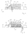
- FIG. 1 shows a partial region 10 of a throughflowable body made of silicon carbide ceramic or cordierite.
- the part provided with reference numeral 1 marks inflowing exhaust gas which flows in an exemplary illustrated, designed as a filter chamber flow area 4.
- the filter chamber 4 is delimited at the inlet opening 7 at the opposite end with a closure 9 designed as a closure wall. Laterally, the cross-sectionally square flow area on all four sides of each, as a filter wall. 2 limited limiting device limited.
- the filter walls 2 are each covered on the side facing the filter chamber 4 with a ceramic layer 12, the thickness of which decreases from the inflow opening 7 to the closure area 9.
- the filter walls 2 are permeable to the exhaust gas, so that the exhaust gas on the other side of the filter walls 2 can leave the filter body shown in sections (see the arrows marked with reference numeral 5, which mark the outflowing exhaust gas).
- the area of the filter chamber 4 facing the inflow opening 7 in this case represents a first area with a first flow resistance for the exhaust gas through the filter wall, and the area of the filter chamber 4 facing the closure area 9 represents a second area 13 with a flow resistance which is smaller
- the filter body through which the exhaust gas can flow is composed of a multiplicity of filter chambers 4, which are arranged parallel to the illustrated filter chamber and adjoin immediately above and below the region shown in FIG.
- the exhaust gas flows in a manner known per se through a filter body, whereby soot can deposit on the filter walls, while the exhaust gas penetrates the permeable filter walls 2 and leaves the flow-through filter body beyond the filter wall delimiting the respective flow region.
- the filter flow is improved by the flow resistance decreases in the flow direction of the exhaust gas.
- the rear region of the filter in the vicinity of the closure regions 9 flows through better. This plays a role especially in the regeneration of a particulate filter, as with a poor flow through the rear area of the heat dissipation is otherwise no longer guaranteed, so that thermal stresses occur, which can lead to damage of the filter.
- the layer 12 on the filter walls 2 was in this case applied to the filter walls 2 forming ceramic substrate.
- the total flow resistance is thus composed of the wall resistance of the substrate and the flow resistance of the additionally applied layer 12.
- the variation of the layer thickness can be adjusted by a suitably selected coating process.
- the layer 12 may be a washcoat in an alternative embodiment, which additionally contains catalytically active components.
- This washcoat coating with a suspension of alumina particles on the support can increase the effective surface significantly, for example by up to three orders of magnitude.
- This Coating may contain precious metals, for example platinum and palladium or mixtures of these components.
- Ceria may also be included in the coating, with ceria assisting storage of oxygen.
- the washcoat or the layer 12 is applied only in the region of the flow regions or filter chambers 4 close to the inflow opening, while, for example, the last centimeter of the ceramic monolith remains uncoated.
- an upstream mask technique it is also possible to work with an upstream mask technique.
- the thickness of the wall material of the filter walls 2 near the closure areas is reduced. This also reduces the wall flow resistance relative to the near-inflow opening region, which produces the already mentioned, positive effect on the flow flow.
- the arrangement or the method of layer application or wall removal can also be used with sintered metal filters, with oxidation catalysts or with NOx storage catalysts.
- neither a layer nor applied wall material is removed. In the filter walls are pores whose surface density or volume density or their average size in front filter areas in a controlled manner can be slightly reduced by introducing additional material.
- the material must withstand the operating conditions of the filter and should therefore consist of a suitable ceramic or precursor material, which is then fixed by tempering or firing. Another possibility is to deposit particles of ceramic or a precursor from the gas phase on the surface of the particle filter so that they preferably deposit in the front region of the filter. The fixation of this layer on the substrate then takes place in a corresponding annealing or firing process.
- FIG. 2 shows a partial region of an alternative ceramic honeycomb filter in which a layer 14 applied to the filter walls 2 has a thickness which increases in the direction of flow of the exhaust gas.
- regions 15 and 16 with different flow resistance are formed, wherein in the present case the flow resistance for the exhaust gas to the closure region 9 increases.
- CRT continuous regenerating trap
- FIG. 3 illustrates in a schematic representation the cross section 17 of a ceramic honeycomb filter according to the invention.
- the flow resistance 19 is shown as a function of the radius r in a diagram.
- the nature of the filter walls 2 (see Figures 1 and 2) is selected so that the radial distribution of the flow resistance shown in the diagram results in the individual, mutually parallel filter chambers.
- the cylinder-shaped filter body in this case has a radius R0.
- the flow resistance is greatest in the center of the filter body and falls off towards the edge. It can be distinguished between two regions 20 and 21 with different flow resistance.
- the first region 20 is located in the center of the filter body and extends from the symmetry axis of the cylindrical filter body to a radius R.
- the second region 21 extends from the radius R to the outer edge of the filter body.
- the flow resistance is increased by a corresponding design of the filter walls in the region 20 in comparison to the flow resistance of the region 21.
- the generation of a higher flow resistance in the center of a filter or catalyst is not limited to a diesel particulate filter, but may also be applied to oxidation catalysts or e.g. NOx storage catalysts lead to a better flow distribution over the cross section and to a better utilization of the catalyst volume. This will be explained in more detail with reference to Figures 4 and 5.
- FIG. 4 shows the cross-sectional side view of a storage catalytic converter 30, wherein, for the sake of simplicity, only one half of the storage catalytic converter is shown on one side of the symmetry line 39.
- An exhaust pipe 31 leads via a diffuser 35 to a region of the storage catalytic converter with flow regions which are formed parallel to one another and flow channels which, starting from the inflow openings 7 facing the diffuser, extend as far as the downstream confuser 37, which in turn flows into a further exhaust pipe 32 empties.
- the flow channels can, for example, have square, circular or even annular cross-sectional areas perpendicular to the exhaust gas flow; in the latter case, the schematic representation is to be interpreted such that for each flow channel only one half of the lateral cross section is always displayed.
- the flow channels 44 are delimited by limiting devices formed as catalytically coated channel walls 46, which, in contrast to the structures depicted in FIGS. 1 to 3, are impermeable to the exhaust gas.
- the lines provided with reference numeral 48 represent flow lines of a flowing exhaust gas, reference numeral 50 denotes whirl lines.
- the cross-sectional areas of the flow channels perpendicular to the main flow direction of the exhaust gas from the exhaust pipe 31 to the exhaust pipe 32 have the same size in the interior of the catalyst as in the edge region of the catalyst. Due to the widening of the flow space in the region of the diffuser, however, marginally exhaust eddies 50 are formed, and the flow channels in the interior of the catalyst are flowed through more than the flow channels lying in the edge region of the catalyst behind the vortex lines 50.
- FIG. 5 shows a modified catalyst device compared to the arrangement according to FIG. Identical or similar components are provided with the same reference numerals as in FIG. 4 and will not be described again.
- the channel walls 46 are covered with layers 53, the thickness of which decreases from the interior of the catalyst near the line of symmetry 39 to the edge region.
- the material of the layers is the same as the material of the channel walls, a catalytically active coating is located instead of on the channel walls 46 on the deposited on the channel walls layers 53.
- the flow lines 55 symbolize the flow of the exhaust gas.
- a first region 57 of low flow resistance is shown by a dashed line and a second region 58 of high flow resistance is shown in the inner region of the catalyst.
- the coating was produced by means of a mask technique, in which in particular the edge regions of a catalyst base body were covered on the end faces before the layers were applied in a dip bath. In the simplest case, some channel walls are coated inside the catalyst, while the channel walls in the edge regions of the catalyst remain uncoated.
- the coating consists of a washcoat coating.
- Thicker layers 53 in the center of the catalyst than in the edge region of the catalyst or layers 53 per se in the center of the catalyst increase the flow resistance in the center of the catalyst compared to the edge region, so that a more uniform flow of all flow channels 4 (the flow resistance in region 58 is higher than in region 57). Due to the decreasing from the center to the edge flow resistance, the flow of the exhaust gas in the edge region compared to the center is just so favored that the existing without coating 53 different flow of the channels with exhaust gas tends to be compensated.
- the catalyst may also be designed as a three-way catalyst, as an oxidation catalyst or as a catalyst for selective catalytic reduction.
- the catalyst base body may also already be manufactured such that the flow channels have a greater flow resistance in the interior of the body than in the edge region. The body then only needs to be uniformly coated with a catalytically active substance, if the body itself is not already contains catalytically active materials.
- the layers 53 may also already contain the catalytically active material. In addition to washcoat coatings, any other possible coating form is also suitable with which a uniform application of material in the flow channels can be achieved.
- the catalyst 30 may also be designed asymmetrically, ie it does not need to have a line of symmetry 39.
Landscapes
- Chemical & Material Sciences (AREA)
- Engineering & Computer Science (AREA)
- Physics & Mathematics (AREA)
- Geometry (AREA)
- Chemical Kinetics & Catalysis (AREA)
- Mechanical Engineering (AREA)
- Combustion & Propulsion (AREA)
- General Engineering & Computer Science (AREA)
- Exhaust Gas After Treatment (AREA)
- Filtering Of Dispersed Particles In Gases (AREA)
- Catalysts (AREA)
- Filtering Materials (AREA)
- Exhaust Gas Treatment By Means Of Catalyst (AREA)
Description
- Die Erfindung geht aus von einer Anordnung zur Abgasnachbehandlung nach der Gattung des unabhängigen Anspruchs.
- Aus der DE 3538107 A1 ist bereits ein Filter zur Reinigung von Abgasen bekannt, bei dem das Material entlang einer Strömungslinie unterschiedliche Porosität aufweist.
- Weiterhin sind bereits aus der DE 3529684 keramische Wabenfilterkörper bekannt. Diese beruhen auf dem Wandstromfilterprinzip. Die vom Abgas mitgeführten Partikel werden an den Rändern von axial angeströmten, am Ende geschlossenen Kanälen an einer Keramikmatrix abgeschieden. Das beladene Abgas passiert hierbei das Keramiksubstrat entsprechend den Strömungsdruckverhältnissen innerhalb des Kanals und der Dicke des Filterkuchens auf dem Keramiksubstrat. Dabei kann das Substrat katalytisch beschichtet sein, wodurch eine Rußoxidation auch bei niedrigeren Temperaturen ermöglicht wird. Nach einer gewissen Betriebsdauer steigt der Druckverlust bei der Durchströmung eines solchen Filters durch den Aufbau des Filtrats deutlich an. Die Regeneration des abgeschiedenen Rußes auf dem Keramiksubstrat erfolgt dann durch Oxidation mit dem Restsauerstoff des Abgases oder durch Zugabe eines Oxidationsmittels, z.B. Ozon oder Stickstoffdioxid. Dabei kann sich ein örtlich unterschiedlicher Abbrand des auf dem Filter befindlichen Rußes ergeben. Kritisch sind hierbei vor allem Betriebszustände, bei denen im hinteren, d.h. dem Einströmungsbereich abgewandten Bereich eine Restrußmenge angesammelt wird. Durch die höhere Filterkuchendichte wird der Gesamtströmungswiderstand über Filterkuchen und Substrat größer als im vorderen Bereich. Die Strömung läuft dann bevorzugt durch den vorderen Filterbereich. Die im hinteren Filterbereich durch die chemische Umsetzung des Rußes freigesetzte Wärme kann nicht mehr ausreichend abgeführt werden. Es ergibt sich eine lokale Überhitzung, verbunden mit sehr hohen Temperaturen, besonders im hinteren Filterbereich. In der Keramikmatrix können sich dadurch starke Temperaturgradienten ausbilden, die zu thermischen Spannungen, bis hin zu Substratbrüchen führen. Ein weiterer negativer Effekt kann die thermische Zerstörung der wirksamen Katalysatorbeschichtung auf dem Wandstromfilter sein, wodurch die Funktion deutlich beeinträchtigt wird.
- Aus der US 4 390 355 ist ein Partikelfilter bekannt, der Einlasskanäle mit in Strömungsrichtung abnehmendem Querschnitt aufweist.
- Die erfindungsgemäße Anordnung mit den kennzeichnenden Merkmalen des unabhängigen Anspruchs hat demgegenüber den Vorteil, einen Filter bzw. einen Katalysator bereitzustellen, der gewährleistet, dass während der Regeneration eine Strömungsführung generiert wird, welche die Gefahr der Ausbildung einer Zone mit geringer Durchströmung und damit erhöhter Temperaturbildung vermindert. Ist die Anordnung als Partikelfilter ausgestaltet, so wird während der Beladung des Filters ein anfänglicher Unterschied in der Permeabilität durch das Wachstum des Filterkuchens, welches in Bereichen höherer Durchströmung verstärkt ist, teilweise kompensiert. Darüber hinaus können in vorteilhafter Weise unterschiedliche Zielrichtungen durch die gezielte Variation der Permeabilität der Begrenzungseinrichtungen verfolgt werden, die unterschiedliche Gradienten im Strömungswiderstand zur Folge haben. Vorteilhaft ist es hierbei, dass sich die Permeabilität zumindest zweier Begrenzungseinrichtungen in einströmöffnungsnahen und/oder in einströmöffnungsfernen Bereichen voneinander unterscheidet, so dass Gebiete unterschiedlichen Strömungswiderstands gebildet werden.
- Durch die in den abhängigen Ansprüchen aufgeführten Maßnahmen sind vorteilhafte Weiterbildungen und Verbesserungen der im unabhängigen Anspruch angegebenen Anordnung möglich.
- Besonders vorteilhaft ist es, die Permeabilität der Begrenzungseinrichtungen bzw. den Strömungswiderstand der Strömungsbereiche durch eine entsprechende Wahl der Dicken der Begrenzungseinrichtungen in Durchströmungsrichtung des Abgases einzustellen. Diese Variation kann in einfacher Weise sowohl in Richtung der einströmenden Gase verlaufen, als auch in radialer Richtung; im letzteren Fall haben unterschiedliche Strömungskanäle in Abhängigkeit von ihrer Position auf einem Substrat eine unterschiedliche Permeabilität bzw. einen unterschiedlichen Strömungswiderstand.
- Insbesondere ist es vorteilhaft, die Permeabilität radial zu variieren, um über den Querschnitt eines Filters bzw. Katalysators eine verbesserte Strömungsverteilung bzw. eine bessere Ausnützung des Katalysators und/oder Filtervolumens zu erzielen. Diese Maßnahme verhindert in vorteilhafter Weise mit vergleichsweise geringem Aufwand ein mögliches Durchbrennen des Filters im Außenbereich, d.h. im Randbereich des Filters, und sorgt für eine bessere Ausnutzung des Volumens. Dadurch wird es auch möglich, kostengünstigere Filtersubstrate zu verwenden, welche eine vergleichsweise geringe Temperaturfestigkeit aufweisen (z.B. Cordierit im Vergleich zu Siliziumkarbid).
- Weitere Vorteile ergeben sich aus den in den abhängigen Ansprüchen und in der Beschreibung genannten Merkmalen.
- Ausführungsbeispiele der Erfindung sind in der Zeichnung dargestellt und in der nachfolgenden Beschreibung näher erläutert.
- Es zeigen
- Figur 1 einen Filter mit Strömungsbereichen mit in Strömungsrichtung abnehmendem Strömungswiderstand, Figur 2 einen Filter mit in Strömungsrichtung des Abgases zunehmendem Strömungswiderstand, Figur 3 ein Ausführungsbeispiel eines Wabenfilters aus Keramik mit einer radialen Variation des Strömungswiderstandes, Figur 4 einen Speicherkatalysator in Querschnittsseitenansicht und Figur 5 ein weiteres Ausführungsbeispiel der Erfindung.
- In Figur 1 ist ein Teilbereich 10 eines aus Siliziumkarbid-Keramik oder Cordierit bestehenden, durchströmbaren Körpers dargestellt. Der mit Bezugszeichen 1 versehene Teil markiert einströmendes Abgas, das in einem exemplarisch dargestellten, als Filterkammer ausgebildeten Strömungsbereich 4 hineinströmt. Die Filterkammer 4 ist an der Einströmöffnung 7 am gegenüberliegenden Ende mit einem als Verschlusswand ausgebildeten Verschluss 9 begrenzt. Seitlich wird der im Querschnitt quadratisch ausgebildete Strömungsbereich auf allen 4 Seiten von jeweils einer, als Filterwand 2 ausgebildeten Begrenzungseinrichtung begrenzt. Die Filterwände 2 sind auf der der Filterkammer 4 zugewandten Seite jeweils mit einer Keramikschicht 12 bedeckt, deren Dicke von der Einströmöffnung 7 hin zum Verschlussbereich 9 abnimmt. Die Filterwände 2 sind für das Abgas durchlässig (permeabel), so dass das Abgas jenseits der Filterwände 2 den ausschnitthaft dargestellten Filterkörper wieder verlassen kann (vgl. die mit Bezugszeichen 5 versehenen Pfeile, die das ausströmende Abgas markieren). Der der Einströmöffnung 7 zugewandte Bereich der Filterkammer 4 stellt hierbei ein erstes Gebiet mit einem ersten Strömungswiderstand für das Abgas durch die Filterwand hindurch dar, und der dem Verschlussbereich 9 zugewandte Bereich der Filterkammer 4 stellt ein zweites Gebiet 13 mit einem Strömungswiderstand dar, der kleiner ist als der Strömungswiderstand des Gebiets 11. Der vom Abgas durchströmbare Filterkörper setzt sich hierbei aus einer Vielzahl von Filterkammern 4 zusammen, die parallel zur abgebildeten Filterkammer angeordnet sind und sich unmittelbar oberhalb und unterhalb des in Figur 1 dargestellten Bereichs anschließen.
- Das Abgas strömt in an sich bekannter Weise durch einen Filterkörper hindurch, wobei sich an den Filterwänden Ruß ablagern kann, während das Abgas die permeablen Filterwände 2 penetriert und jenseits der den jeweiligen Strömungsbereich begrenzenden Filterwände den durchströmbaren Filterkörper wieder verlässt. Durch die zusätzliche Schicht 12 wird die Filterdurchströmung verbessert, indem der Strömungswiderstand in Strömungsrichtung des Abgases abnimmt. Dadurch wird der hintere Bereich des Filters in der Nähe der Verschlussbereiche 9 besser durchströmt. Dies spielt vor allem bei der Regeneration eines Partikelfilters eine Rolle, da bei einer schlechten Durchströmung des hinteren Bereichs der Wärmeabfluss ansonsten nicht mehr gewährleistet ist, so dass Wärmespannungen auftreten, die zu einer Beschädigung des Filters führen können. Die Schicht 12 auf den Filterwänden 2 wurde hierbei auf das die Filterwände 2 bildende Keramiksubstrat aufgetragen. Der gesamte Strömungswiderstand setzt sich somit aus dem Wandwiderstand des Substrates und dem Strömungswiderstand der zusätzlich aufgebrachten Schicht 12 zusammen. Die Variation der Schichtdicke kann durch einen entsprechend gewählten Beschichtungsprozess eingestellt werden.
- Die Schicht 12 kann in einer alternativen Ausgestaltung ein Washcoat sein, welcher zusätzlich katalytisch wirksame Komponenten enthält. Diese Washcoat-Beschichtung mit einer Suspension von Aluminiumoxidpartikeln auf der Trägersubstanz kann die wirksame Oberfläche deutlich, zum Beispiel um bis zu drei Größenordnungen, vergrößern. In dieser Beschichtung können Edelmetalle, zum Beispiel Platin und Palladium bzw. Mischungen dieser Komponenten, enthalten sein. Auch Ceroxid kann in der Beschichtung enthalten sein, wobei Ceroxid eine Einspeicherung von Sauerstoff unterstützt. In einer vereinfachten Ausgestaltung wird der Washcoat bzw. die Schicht 12 nur im einströmöffnungsnahen Bereich der Strömungsbereiche bzw. Filterkammern 4 aufgebracht, während beispielsweise der letzte Zentimeter des Keramikmonoliths unbeschichtet bleibt. Neben einer Tauchtechnik mit entsprechend verringerter Eintauchtiefe für die Washcoat-Beschichtung kann auch mit einer vorgelagerten Maskentechnik gearbeitet werden. In einer weiteren alternativen Ausgestaltung wird anstelle eines Aufbringens der Schicht 12 die Dicke des Wandmaterials der Filterwände 2 nahe der Verschlussbereiche verringert. Dies verkleinert ebenfalls den Wandströmungswiderstand relativ zum einströmungsöffnungsnahen Bereich, was den bereits genannten, positiven Effekt auf den Strömungsfluß erzeugt. Außer bei Keramikwabenfiltern ist die Anordnung bzw. das Verfahren der Schichtauftragung bzw. der Wandabtragung auch bei Sintermetallfiltern, bei Oxidationskatalysatoren oder bei NOx-Speicherkatalysatoren einsetzbar. In einer weiteren alternativen Ausgestaltung wird weder eine Schicht aufgebracht noch Wandmaterial abgetragen. In den Filterwänden sind Poren enthalten, deren Flächendichte bzw. deren Volumendichte bzw. deren durchschnittliche Größe in vorderen Filterbereichen in kontrollierter Weise geringfügig durch Einbringen zusätzlichen Materials verkleinert werden kann. Das Material muss hierbei den Betriebsbedingungen des Filters standhalten und sollte deshalb aus einem geeigneten Keramik- oder Precursor-Material bestehen, welches anschließend durch Tempern oder Brennen fixiert wird. Eine weitere Möglichkeit besteht darin, aus der Gasphase Partikel aus Keramik oder einem Precursor so auf der Oberfläche des Partikelfilters abzuscheiden, dass sich diese bevorzugt im vorderen Bereich des Filters ablagern. Die Fixierung dieser Schicht auf dem Substrat erfolgt dann in einem entsprechenden Temper- oder Brennprozess.
- Figur 2 zeigt einen Teilbereich eines alternativen Wabenfilters aus Keramik, bei dem eine auf den Filterwänden 2 aufgebrachte Schicht 14 eine Dicke aufweist, die in Strömungsrichtung des Abgases zunimmt. Hierbei bilden sich analog zur in Figur 1 dargestellten Anordnung 2 Gebiete 15 und 16 mit unterschiedlichem Strömungswiderstand aus, wobei im vorliegenden Fall der Strömungswiderstand für das Abgas zum Verschlussbereich 9 zunimmt.
- Ziel dieser Form der Gradientenschicht ist es, eine Ansammlung von Ruß im hinteren Bereich des Filters zu vermeiden. Aufgrund des geringeren Strömungswiderstandes am Eintritt des Filters wird ein großer Teil der Strömung in diesem Bereich fließen, so dass sich an dieser Stelle auch das Maximum an Ruß ablagern wird. Im vorderen Bereich des Filters ist die Regeneration unter Ausnutzung des CRT-Effekts ("CRT"="continuously regenerating trap") jedoch unproblematischer. Der Ruß im vorderen Filterbereich wird häufig durch Stickstoffdioxid oxidiert und verbrennt bei einer thermischen Oxidation zuerst, so dass der konvektive Abtransport der Reaktionswärme verbunden mit einer guten Durchströmung gewährleistet ist.
- Figur 3 illustriert in schematischer Darstellung den Querschnitt 17 eines erFndungsgemäßen Keramikwabenfilters. Oberhalb des Querschnitts 17 ist in einem Diagramm der Strömungswiderstand 19 in Abhängigkeit vom Radius r dargestellt. Die Beschaffenheit der Filterwände 2 (vgl. Figur 1 und 2) ist so gewählt, dass sich die im Diagramm abgebildete radiale Verteilung des Strömungswiderstandes in den einzelnen, parallel zueinander angeordneten Filterkammern ergibt. Der zylinderförmig ausgebildete Filterkörper weist hierbei einen Radius R0 auf. Der Strömungswiderstand ist im Zentrum des Filterkörpers am größten und fällt zum Rand hin ab. Dabei kann zwischen zwei Gebieten 20 und 21 mit unterschiedlichem Strömungswiderstand unterschieden werden. Das erste Gebiet 20 befindet sich im Zentrum des Filterkörpers und reicht von der Symmetrieachse des zylindrischen Filterkörpers bis zu einem Radius R. Das zweite Gebiet 21 geht vom Radius R bis zum äußeren Rand des Filterkörpers. Dabei ist der Strömungswiderstand durch eine entsprechende Gestaltung der Filterwände im Gebiet 20 im Vergleich zum Strömungswiderstand des Gebietes 21 erhöht.
- Durch die Variation des Strömungswiderstands in radialer Richtung soll eine gleichmäßige Durchströmung des Filters unterstützt werden. Häufig tritt bei Filtern das Problem auf, dass nur der mittlere Bereich des Filters durchströmt wird. Bei Dieselpartikelfiltern kann dies dazu führen, dass sich in den äußeren Bereichen des Filters größere Mengen Ruß absetzen, was bei einer Regeneration zu einer erhöhten Temperaturbelastung führen kann, wenn dieser Bereich nicht gut durchströmt wird. Durch einen erhöhten Strömungswiderstand im mittleren Bereich des Filters, also im Gebiet 20, verlagert sich die Strömung mehr in die äußeren Bereiche des Filters. Auch durch einen radialen Gradient im Strömungswiderstand der einzelnen Filterkanäle, d.h. einer unterschiedlich ausgestalteten Permeabilität von unterschiedlichen Strömungskanälen, kann eine Verbesserung der Filterdurchströmung erzielt werden.
- Die Erzeugung eines höheren Strömungswiderstands in der Mitte eines Filters oder Katalysators ist nicht auf einen Dieselpartikelfilter beschränkt, sondern kann auch bei Oxidationskatalysatoren oder z.B. NOx-Speicherkatalysatoren zu einer besseren Strömungsverteilung über den Querschnitt und zu einer besseren Ausnutzung des Katalysatorvolumens führen. Dies wird anhand der Figuren 4 und 5 näher erläutert.
- Figur 4 zeigt die Querschnittsseitenansicht eines Speicherkatalysators 30, wobei der Einfachheit halber nur eine Hälfte des Speicherkatalysators auf einer Seite der Symmetrielinie 39 dargestellt ist. Eine Abgasleitung 31 führt über einen Diffusor 35 zu einem Bereich des Speicherkatalysators mit parallel zueinander verlaufenden als Strömungskanäle 44 ausgebildeten Strömungsbereichen, die, ausgehend von dem Diffusor zugewandten Einströmöffnungen 7, sich bis zum sich stromabwärts anschließenden Konfusor 37 erstrecken, der wiederum in eine weiterführende Abgasleitung 32 mündet. Die Strömungskanäle können beispielsweise quadratische, kreisförmige oder auch kreisringförmige Querschnittsflächen senkrecht zur Abgasströmung haben; im letzteren Fall ist die schematische Darstellung so zu interpretieren, dass für jeden Strömungskanal immer nur eine Hälfte des Seitenquerschnitts abgebildet ist. Die Strömungskanäle 44 sind von als katalytisch beschichtete Kanalwände 46 ausgebildeten Begrenzungseinrichtungen begrenzt, die im Unterschied zu den in den Figuren 1 bis 3 abgebildeten Strukturen für das Abgas undurchlässig ausgebildet sind. Die mit Bezugszeichen 48 versehenen Linien stellen Strömungslinien eines strömenden Abgases dar, mit Bezugszeichen 50 sind Wirbellinien bezeichnet.
- Die Querschnittsflächen der Strömungskanäle senkrecht zur Hauptströmungsrichtung des Abgases von der Abgasleitung 31 zur Abgasleitung 32 haben im Inneren des Katalysators wie im Randbereich des Katalysators die gleiche Größe. Bedingt durch die Aufweitung des Strömungsraums im Bereich des Diffusors bilden sich jedoch randständig Abgaswirbel 50 aus, und die Strömungskanäle im Inneren des Katalysators werden stärker durchströmt als die im Randbereich des Katalysators hinter den Wirbellinien 50 liegenden Strömungskanäle.
- Figur 5 zeigt eine im Vergleich zur Anordnung nach Figur 4 abgeänderte Katalysatorvorrichtung. Gleiche oder ähnliche Bestandteile sind mit gleichem Bezugszeichen wie in Figur 4 versehen und werden nicht nochmals beschrieben. Die Kanalwände 46 sind mit Schichten 53 bedeckt, deren Dicke vom Inneren des Katalysators nahe der Symmetrielinie 39 ausgehend hin zum Randbereich abnimmt. Das Material der Schichten ist das gleiche wie das Material der Kanalwände, eine katalytisch aktive Beschichtung befindet sich statt auf den Kanalwänden 46 auf den auf den Kanalwänden aufgebrachten Schichten 53. Die Strömungslinien 55 symbolisieren den Strömungsverlauf des Abgases. Im Randbereich des Katalysators ist mit gestrichelter Linie ein erstes Gebiet 57 niedrigen Strömungswiderstands und im inneren Bereich des Katalysators ein zweites Gebiet 58 hohen Strömungswiderstands eingezeichnet. Die Beschichtung ist mittels einer Maskentechnik erzeugt worden, bei der insbesondere die Randbereiche eines Katalysatorgrundkörpers auf den Stirnseiten abgedeckt wurden, bevor die Schichten in einem Tauchbad aufgebracht wurden. Im einfachsten Fall sind einige Kanalwände im Inneren des Katalysators beschichtet, während die Kanalwände in Randbereichen des Katalysators unbeschichtet bleiben. Die Beschichtung besteht aus einem Washcoat-Überzug.
- Dickere Schichten 53 im Zentrum des Katalysators als im Randbereich des Katalysators bzw. Schichten 53 an sich im Zentrum des Katalysators (im Vergleich zu schichtfreien Bereichen im Randbereich) erhöhen den Strömungswiderstand im Zentrum des Katalysators im Vergleich zum Randbereich, so dass eine gleichmässigere Beströmung aller Strömungskanäle im Vergleich zur Anordnung nach Figur 4 gewährleistet ist (der Strömungswiderstand im Gebiet 58 ist höher als im Gebiet 57). Durch den vom Zentrum zum Rand hin abnehmenden Strömungswiderstand wird die Strömung des Abgases im Randbereich im Vergleich zum Zentrum gerade so begünstigt, dass die ohne Beschichtung 53 bestehende unterschiedliche Beströmung der Kanäle mit Abgas tendenziell ausgeglichen wird.
- Der Katalysator kann alternativ auch als Dreiwegekatalysator, als Oxidationskatalysator oder als Katalysator zur selektiven katalytischen Reduktion ausgebildet sein. In einer Ausführungsvariante kann der Katalysatorgrundkörper auch bereits so gefertigt sein, dass die Strömungskanäle im Inneren des Körpers einen größeren Strömungswiderstand aufweisen als im Randbereich. Der Körper braucht dann nur noch gleichmässig mit einer katalytisch aktiven Substanz beschichtet zu werden, falls der Grundkörper an sich nicht schon katalytisch aktive Materialien enthält. In einer weiteren alternativen Ausführungsform können die Schichten 53 auch bereits das katalytisch aktive Material enthalten. Neben Washcoat-Überzügen ist auch jede andere mögliche Beschichtungsform geeignet, mit der ein gleichmässiger Materialauftrag in den Strömungskanälen erzielt werden kann. Der Katalysator 30 kann in einer alternativen Ausfiihrungsform auch asymmetrisch ausgebildet sein, braucht also keine Symmetrielinie 39 aufzuweisen.
Claims (12)
- Abgasnachbehandlungsanordnung mit einem vom Abgas einer Brennkraftmaschine durchströmbaren Körper, wobei der Körper voneinander abgegrenzte, von jeweils einer Begrenzungseinrichtung (2, 12, 14, 46) begrenzte Strömungsbereiche (4, 44) mit jeweils mindestens einer mit Abgas beaufschlagbaren Einströmöffnung (7) aufweist, wobei die Begrenzungseinrichtungen für das Abgas permeabel sind und im Abgas enthaltene Rußteilchen zurückgehalten werden können, dadurch gekennzeichnet, dass die Permeabilität der Begrenzungseinrichtungen variiert, indem sich die Permeabilität zumindest zweier Begrenzungseinrichtungen in einströmöffnungsnahen und/oder in einströmöffnungsfernen Bereichen voneinander unterscheidet, so dass Gebiete unterschiedlichen Strömungswiderstands gebildet werden.
- Abgasnachbehandlungsanordnung nach Anspruch 1, dadurch gekennzeichnet, dass die unterschiedliche Permeabilität der Begrenzungseinrichtungen zumindest teilweise durch entsprechend gewählte Dicken der Begrenzungseinrichtungen bedingt ist.
- Abgasnachbehandlungsanordnung nach einem der vorhergehenden Ansprüche, dadurch gekennzeichnet, dass die Begrenzungseinrichtungen jeweils eine Wand und eine die Wand zumindest teilweise bedeckende Schicht (12, 14, 53) aufweisen, wobei die Dicke der Schicht variiert.
- Abgasnachhehandlungsanordnung nach einem der vorhergehenden Ansprüche, dadurch gekennzeichnet, daß sich die Permeabilität mindestens einer Begrenzungseinrichtung in einem der Einströmöffnung zugewandten Bereich (11; 15) der Begrenzungseinrichtung von der Permeabilität der Begrenzungseinrichtung in einem der Einströmöffnung abgewandten Bereich (13; 16) unterscheidet.
- Abgasnachbehandlungsanordnung nach einem der vorhergehenden Ansprüche, dadurch gekennzeichnet, dass die Begrenzungseinrichtungen zumindest teilweise aus porösem Material bestehen und dass die unterschiedliche Permeabilität der Begrenzungseinrichtungen zumindest teilweise durch entsprechend gewählte Porendichten und/oder Porengrößen in den Gebieten bedingt ist.
- Abgasnachbehandlungsanordnung nach einem der vorhergehenden Ansprüche, dadurch gekennzeichnet, daß die Strömungsbereiche Querschnittsflächen senkrecht zur Strömungsrichtung des Abgases aufweisen und dass die Begrenzungseinrichtungen derartig unterschiedlich ausgestaltet sind, daß sich die Flächeninhalte der Querschnittsflächen in den Gebieten voneinander unterscheiden.
- Abgasnachbehandlungsanordnung nach einem der vorhergehenden Ansprüche, dadurch gekennzeichnet, dass der durchströmbare Körper einen Oxidationskatalysator oder einen Speicherkatalysator (30) zur Abgasentstickung bildet.
- Abgasnachbehandlungsanordnung nach einem der vorhergehenden Ansprüche, dadurch gekennzeichnet, dass der durchströmbare Körper ein Partikelfilter bildet.
- Abgasnachbehandlungsanordnung nach einem der vorhergehenden Ansprüche, dadurch gekennzeichnet, dass die Begrenzungseinrichtungen durch Keramikwände gebildet werden.
- Abgasnachbehandlungsanordnung nach einem der vorhergehenden Ansprüche, dadurch gekennzeichnet, dass die Begrenzungseinrichtungen durch Metallgeflechte gebildet werden.
- Abgasnachbehandlungsanordnung nach Anspruch 10, dadurch gekennzeichnet, dass das Filter ein Sintermetallfilter ist.
- Abgasnachbehandlungsanordnung nach einem der vorhergehenden Ansprüche, dadurch gekennzeichnet, dass die Strömungsbereiche parallel zueinander angeordnet ist, so dass sich deren Einströmöffnungen auf einer Seite des Körpers befinden.
Applications Claiming Priority (3)
| Application Number | Priority Date | Filing Date | Title |
|---|---|---|---|
| DE10247946A DE10247946A1 (de) | 2002-10-15 | 2002-10-15 | Abgasnachbehandlungsanordnung |
| DE10247946 | 2002-10-15 | ||
| PCT/DE2003/002100 WO2004036003A1 (de) | 2002-10-15 | 2003-06-24 | Abgasnachbehandlungsanordnung |
Publications (2)
| Publication Number | Publication Date |
|---|---|
| EP1554473A1 EP1554473A1 (de) | 2005-07-20 |
| EP1554473B1 true EP1554473B1 (de) | 2006-12-20 |
Family
ID=32049262
Family Applications (1)
| Application Number | Title | Priority Date | Filing Date |
|---|---|---|---|
| EP03808663A Expired - Lifetime EP1554473B1 (de) | 2002-10-15 | 2003-06-24 | Abgasnachbehandlungsanordnung |
Country Status (7)
| Country | Link |
|---|---|
| US (1) | US20060008396A1 (de) |
| EP (1) | EP1554473B1 (de) |
| JP (1) | JP2006502842A (de) |
| KR (1) | KR20050059260A (de) |
| CN (1) | CN1688799A (de) |
| DE (2) | DE10247946A1 (de) |
| WO (1) | WO2004036003A1 (de) |
Cited By (1)
| Publication number | Priority date | Publication date | Assignee | Title |
|---|---|---|---|---|
| CN106321196A (zh) * | 2016-08-31 | 2017-01-11 | 芜湖恒耀汽车零部件有限公司 | 汽车尾气过滤装置 |
Families Citing this family (27)
| Publication number | Priority date | Publication date | Assignee | Title |
|---|---|---|---|---|
| DE102004012159A1 (de) * | 2004-03-12 | 2005-09-29 | Adam Opel Ag | Monolithischer Katalysator |
| JP2007130624A (ja) * | 2005-10-14 | 2007-05-31 | Matsushita Electric Ind Co Ltd | 排ガス浄化フィルタ |
| US7722827B2 (en) * | 2006-03-31 | 2010-05-25 | Corning Incorporated | Catalytic flow-through fast light off ceramic substrate and method of manufacture |
| FR2918706B1 (fr) * | 2007-07-11 | 2009-10-30 | Peugeot Citroen Automobiles Sa | Dispositif de traitement des emissions gazeuses d'un moteur. |
| US8038954B2 (en) * | 2008-02-14 | 2011-10-18 | Basf Corporation | CSF with low platinum/palladium ratios |
| WO2009118867A1 (ja) | 2008-03-27 | 2009-10-01 | イビデン株式会社 | ハニカム構造体および排ガス処理装置 |
| WO2009141890A1 (ja) * | 2008-05-20 | 2009-11-26 | イビデン株式会社 | ハニカム構造体および排ガス浄化装置 |
| JP5349108B2 (ja) * | 2009-03-26 | 2013-11-20 | 日本碍子株式会社 | ハニカムフィルタ |
| JP5456353B2 (ja) * | 2009-03-31 | 2014-03-26 | 日本碍子株式会社 | ハニカムフィルタ |
| US8273315B2 (en) * | 2010-08-09 | 2012-09-25 | Ford Global Technologies, Llc | Engine emission control system |
| EP2603320B1 (de) * | 2010-08-09 | 2016-02-10 | Cormetech, Inc. | Katalytischer körper |
| US9724634B2 (en) * | 2012-03-30 | 2017-08-08 | Ibiden Co., Ltd. | Honeycomb filter and method for producing honeycomb filter |
| JP6158832B2 (ja) | 2012-12-03 | 2017-07-05 | トヨタ自動車株式会社 | 排気浄化フィルタ |
| JP6007864B2 (ja) * | 2013-06-10 | 2016-10-12 | トヨタ自動車株式会社 | 排気浄化フィルタ |
| JP2016022397A (ja) * | 2014-07-16 | 2016-02-08 | 住友化学株式会社 | ハニカムフィルタ |
| GB2542654B (en) * | 2015-06-28 | 2019-12-04 | Johnson Matthey Plc | Catalytic wall-flow filter having a membrane |
| GB2546164A (en) * | 2015-09-30 | 2017-07-12 | Johnson Matthey Plc | Gasoline particulate filter |
| GB2545747A (en) * | 2015-12-24 | 2017-06-28 | Johnson Matthey Plc | Gasoline particulate filter |
| DE102017106374A1 (de) | 2016-04-01 | 2017-10-05 | Johnson Matthey Public Limited Company | Abgasreinigungsfilter |
| CN108201749A (zh) * | 2016-12-17 | 2018-06-26 | 重庆市银盛模具有限公司 | 处理废气的结构 |
| JP7037985B2 (ja) * | 2018-03-30 | 2022-03-17 | 日本碍子株式会社 | ハニカムフィルタ |
| DE102019100097B4 (de) | 2019-01-04 | 2021-12-16 | Umicore Ag & Co. Kg | Verfahren zur Herstellung von katalytisch aktiven Wandflussfiltern |
| KR102847669B1 (ko) * | 2020-11-25 | 2025-08-22 | 한국전력공사 | 복합촉매층을 포함하는 디젤분진필터 장치 및 디젤분진필터 장치의 복합촉매층 형성방법 |
| SE545100C2 (en) | 2020-12-03 | 2023-03-28 | Camfil Ab | An air filtration cassette comprising a tapered filter medium with an open interior space, an air filter and a filter arrangement |
| JP7271610B2 (ja) * | 2021-06-17 | 2023-05-11 | 株式会社キャタラー | パティキュレートフィルタ |
| US11772025B1 (en) | 2022-08-02 | 2023-10-03 | W. L. Gore & Associates, Inc. | Industrial filter assembly enhancement |
| EP4424407A1 (de) * | 2023-02-28 | 2024-09-04 | Umicore AG & Co. KG | Gpf mit verbesserter grundierungsverteilung |
Family Cites Families (3)
| Publication number | Priority date | Publication date | Assignee | Title |
|---|---|---|---|---|
| US4390355A (en) * | 1982-02-02 | 1983-06-28 | General Motors Corporation | Wall-flow monolith filter |
| US4846906A (en) * | 1987-12-02 | 1989-07-11 | The Duriron Company, Inc. | Methods for the manufacture of porous ceramic shapes containing membraneous surfaces |
| JP4427658B2 (ja) * | 1998-07-07 | 2010-03-10 | コーニング インコーポレイテッド | ディーゼル排出ガスフィルター |
-
2002
- 2002-10-15 DE DE10247946A patent/DE10247946A1/de not_active Withdrawn
-
2003
- 2003-06-24 US US10/531,278 patent/US20060008396A1/en not_active Abandoned
- 2003-06-24 DE DE50306063T patent/DE50306063D1/de not_active Expired - Lifetime
- 2003-06-24 CN CNA038243059A patent/CN1688799A/zh active Pending
- 2003-06-24 EP EP03808663A patent/EP1554473B1/de not_active Expired - Lifetime
- 2003-06-24 WO PCT/DE2003/002100 patent/WO2004036003A1/de not_active Ceased
- 2003-06-24 JP JP2004543926A patent/JP2006502842A/ja not_active Withdrawn
- 2003-06-24 KR KR1020057006425A patent/KR20050059260A/ko not_active Withdrawn
Cited By (1)
| Publication number | Priority date | Publication date | Assignee | Title |
|---|---|---|---|---|
| CN106321196A (zh) * | 2016-08-31 | 2017-01-11 | 芜湖恒耀汽车零部件有限公司 | 汽车尾气过滤装置 |
Also Published As
| Publication number | Publication date |
|---|---|
| DE50306063D1 (de) | 2007-02-01 |
| EP1554473A1 (de) | 2005-07-20 |
| DE10247946A1 (de) | 2004-04-29 |
| JP2006502842A (ja) | 2006-01-26 |
| KR20050059260A (ko) | 2005-06-17 |
| WO2004036003A1 (de) | 2004-04-29 |
| US20060008396A1 (en) | 2006-01-12 |
| CN1688799A (zh) | 2005-10-26 |
Similar Documents
| Publication | Publication Date | Title |
|---|---|---|
| EP1554473B1 (de) | Abgasnachbehandlungsanordnung | |
| DE60020070T2 (de) | Katalytischer wabenköper-filter mit porösen trennwänden | |
| DE102016111766A1 (de) | Katalytischer wandstromfilter, der eine membran aufweist | |
| DE102017125192A1 (de) | Katalytisches Wandstromfilter mit partieller Oberflächenbeschichtung | |
| DE4005189A1 (de) | Abgasreinigungsvorrichtung fuer einen dieselmotor | |
| DE102020110011A1 (de) | Abgasreinigungsvorrichtung | |
| EP1433519B1 (de) | Verfahren zur Herstellung eines Partikelfilter mit NOx-Speicherkatalysatorfunktion | |
| DE102015212788A1 (de) | Katalytisch aktives Partikelfilter | |
| DE102005023518B4 (de) | Verstopfungsfreies Filteraggregat mit hohem Wirkungsgrad | |
| DE102005005663A1 (de) | Abgasnachbehandlungseinrichtung mit Partikelfilter | |
| DE102005044494B3 (de) | Vorrichtung zur Beseitigung von schädlichen Bestandteilen aus Abgasen von Brennkraftmaschinen | |
| DE102016225629A1 (de) | Abgassystem und Steuerverfahren von Stickoxiddesorption | |
| DE60212245T2 (de) | Verfahren und Vorrichtung zum Entfernen von Russpartikeln aus dem Abgas eines Dieselmotors | |
| EP2166203B1 (de) | Vorrichtung zur Reinigung eines Abgasstroms einer Brennkraftmaschine eines Kraftfahrzeuges, insbesondere eines Nutzfahrzeuges | |
| DE102007056213A1 (de) | Verfahren zur Herstellung eines von Abgas durchströmbaren Formkörpers sowie Abgasanlage einer Brennkraftmaschine | |
| WO2015074698A1 (de) | Als wandstromfilter ausgelegter partikelfilter | |
| DE19961483B4 (de) | Reinigungskatalysator für das Abgas eines Verbrennungsmotors | |
| EP2659950B1 (de) | Abgasnachbehandlungssystem | |
| WO2004047958A2 (de) | Katalysator und verfahren zur beschichtung eines katalysatorträgers enthaltend zwei unterschiedliche teilstrukturen mit einer katalytisch aktiven beschichtung | |
| DE102008003044B4 (de) | Abgasreinigungssystem zur verbesserten Abgasreinigung durch konvektives Mischen | |
| WO2009000667A2 (de) | Herstellungsverfahren und katalysatorelement mit axial veränderlicher katalytischer beschichtung | |
| WO2005046869A1 (de) | Abgassystem für eine brennkraftmaschine | |
| EP2699770B1 (de) | Partikelfilter mit katalytischer beschichtung | |
| EP3582876B1 (de) | Russpartikelfilter mit speicherzellen für katalysator | |
| DE102005032954B4 (de) | Partikelfilter für Abgase |
Legal Events
| Date | Code | Title | Description |
|---|---|---|---|
| PUAI | Public reference made under article 153(3) epc to a published international application that has entered the european phase |
Free format text: ORIGINAL CODE: 0009012 |
|
| 17P | Request for examination filed |
Effective date: 20050517 |
|
| AK | Designated contracting states |
Kind code of ref document: A1 Designated state(s): AT BE BG CH CY CZ DE DK EE ES FI FR GB GR HU IE IT LI LU MC NL PT RO SE SI SK TR |
|
| RBV | Designated contracting states (corrected) |
Designated state(s): DE FR GB IT |
|
| GRAP | Despatch of communication of intention to grant a patent |
Free format text: ORIGINAL CODE: EPIDOSNIGR1 |
|
| GRAS | Grant fee paid |
Free format text: ORIGINAL CODE: EPIDOSNIGR3 |
|
| GRAA | (expected) grant |
Free format text: ORIGINAL CODE: 0009210 |
|
| AK | Designated contracting states |
Kind code of ref document: B1 Designated state(s): DE FR GB IT |
|
| REG | Reference to a national code |
Ref country code: GB Ref legal event code: FG4D Free format text: NOT ENGLISH |
|
| REF | Corresponds to: |
Ref document number: 50306063 Country of ref document: DE Date of ref document: 20070201 Kind code of ref document: P |
|
| ET | Fr: translation filed | ||
| PLBE | No opposition filed within time limit |
Free format text: ORIGINAL CODE: 0009261 |
|
| STAA | Information on the status of an ep patent application or granted ep patent |
Free format text: STATUS: NO OPPOSITION FILED WITHIN TIME LIMIT |
|
| 26N | No opposition filed |
Effective date: 20070921 |
|
| PGFP | Annual fee paid to national office [announced via postgrant information from national office to epo] |
Ref country code: GB Payment date: 20120621 Year of fee payment: 10 Ref country code: FR Payment date: 20120705 Year of fee payment: 10 |
|
| PGFP | Annual fee paid to national office [announced via postgrant information from national office to epo] |
Ref country code: IT Payment date: 20120626 Year of fee payment: 10 |
|
| PGFP | Annual fee paid to national office [announced via postgrant information from national office to epo] |
Ref country code: DE Payment date: 20120822 Year of fee payment: 10 |
|
| GBPC | Gb: european patent ceased through non-payment of renewal fee |
Effective date: 20130624 |
|
| REG | Reference to a national code |
Ref country code: DE Ref legal event code: R119 Ref document number: 50306063 Country of ref document: DE Effective date: 20140101 |
|
| REG | Reference to a national code |
Ref country code: FR Ref legal event code: ST Effective date: 20140228 |
|
| PG25 | Lapsed in a contracting state [announced via postgrant information from national office to epo] |
Ref country code: GB Free format text: LAPSE BECAUSE OF NON-PAYMENT OF DUE FEES Effective date: 20130624 Ref country code: DE Free format text: LAPSE BECAUSE OF NON-PAYMENT OF DUE FEES Effective date: 20140101 |
|
| PG25 | Lapsed in a contracting state [announced via postgrant information from national office to epo] |
Ref country code: FR Free format text: LAPSE BECAUSE OF NON-PAYMENT OF DUE FEES Effective date: 20130701 Ref country code: IT Free format text: LAPSE BECAUSE OF NON-PAYMENT OF DUE FEES Effective date: 20130624 |