EP1554473B1 - Systeme de post-traitement de gaz d'echappement - Google Patents
Systeme de post-traitement de gaz d'echappement Download PDFInfo
- Publication number
- EP1554473B1 EP1554473B1 EP03808663A EP03808663A EP1554473B1 EP 1554473 B1 EP1554473 B1 EP 1554473B1 EP 03808663 A EP03808663 A EP 03808663A EP 03808663 A EP03808663 A EP 03808663A EP 1554473 B1 EP1554473 B1 EP 1554473B1
- Authority
- EP
- European Patent Office
- Prior art keywords
- filter
- flow
- treatment arrangement
- delimiting
- arrangement according
- Prior art date
- Legal status (The legal status is an assumption and is not a legal conclusion. Google has not performed a legal analysis and makes no representation as to the accuracy of the status listed.)
- Expired - Lifetime
Links
Images

Classifications
-
- F—MECHANICAL ENGINEERING; LIGHTING; HEATING; WEAPONS; BLASTING
- F01—MACHINES OR ENGINES IN GENERAL; ENGINE PLANTS IN GENERAL; STEAM ENGINES
- F01N—GAS-FLOW SILENCERS OR EXHAUST APPARATUS FOR MACHINES OR ENGINES IN GENERAL; GAS-FLOW SILENCERS OR EXHAUST APPARATUS FOR INTERNAL-COMBUSTION ENGINES
- F01N3/00—Exhaust or silencing apparatus having means for purifying, rendering innocuous, or otherwise treating exhaust
- F01N3/02—Exhaust or silencing apparatus having means for purifying, rendering innocuous, or otherwise treating exhaust for cooling, or for removing solid constituents of, exhaust
- F01N3/021—Exhaust or silencing apparatus having means for purifying, rendering innocuous, or otherwise treating exhaust for cooling, or for removing solid constituents of, exhaust by means of filters
- F01N3/022—Exhaust or silencing apparatus having means for purifying, rendering innocuous, or otherwise treating exhaust for cooling, or for removing solid constituents of, exhaust by means of filters characterised by specially adapted filtering structure, e.g. honeycomb, mesh or fibrous
-
- B—PERFORMING OPERATIONS; TRANSPORTING
- B01—PHYSICAL OR CHEMICAL PROCESSES OR APPARATUS IN GENERAL
- B01D—SEPARATION
- B01D46/00—Filters or filtering processes specially modified for separating dispersed particles from gases or vapours
- B01D46/24—Particle separators, e.g. dust precipitators, using rigid hollow filter bodies
- B01D46/2403—Particle separators, e.g. dust precipitators, using rigid hollow filter bodies characterised by the physical shape or structure of the filtering element
- B01D46/2418—Honeycomb filters
- B01D46/2425—Honeycomb filters characterized by parameters related to the physical properties of the honeycomb structure material
-
- B—PERFORMING OPERATIONS; TRANSPORTING
- B01—PHYSICAL OR CHEMICAL PROCESSES OR APPARATUS IN GENERAL
- B01D—SEPARATION
- B01D46/00—Filters or filtering processes specially modified for separating dispersed particles from gases or vapours
- B01D46/10—Particle separators, e.g. dust precipitators, using filter plates, sheets or pads having plane surfaces
- B01D46/12—Particle separators, e.g. dust precipitators, using filter plates, sheets or pads having plane surfaces in multiple arrangements
-
- B—PERFORMING OPERATIONS; TRANSPORTING
- B01—PHYSICAL OR CHEMICAL PROCESSES OR APPARATUS IN GENERAL
- B01D—SEPARATION
- B01D46/00—Filters or filtering processes specially modified for separating dispersed particles from gases or vapours
- B01D46/24—Particle separators, e.g. dust precipitators, using rigid hollow filter bodies
- B01D46/2403—Particle separators, e.g. dust precipitators, using rigid hollow filter bodies characterised by the physical shape or structure of the filtering element
- B01D46/2418—Honeycomb filters
- B01D46/2425—Honeycomb filters characterized by parameters related to the physical properties of the honeycomb structure material
- B01D46/24492—Pore diameter
-
- B—PERFORMING OPERATIONS; TRANSPORTING
- B01—PHYSICAL OR CHEMICAL PROCESSES OR APPARATUS IN GENERAL
- B01D—SEPARATION
- B01D46/00—Filters or filtering processes specially modified for separating dispersed particles from gases or vapours
- B01D46/24—Particle separators, e.g. dust precipitators, using rigid hollow filter bodies
- B01D46/2403—Particle separators, e.g. dust precipitators, using rigid hollow filter bodies characterised by the physical shape or structure of the filtering element
- B01D46/2418—Honeycomb filters
- B01D46/2451—Honeycomb filters characterized by the geometrical structure, shape, pattern or configuration or parameters related to the geometry of the structure
-
- B—PERFORMING OPERATIONS; TRANSPORTING
- B01—PHYSICAL OR CHEMICAL PROCESSES OR APPARATUS IN GENERAL
- B01D—SEPARATION
- B01D46/00—Filters or filtering processes specially modified for separating dispersed particles from gases or vapours
- B01D46/24—Particle separators, e.g. dust precipitators, using rigid hollow filter bodies
- B01D46/2403—Particle separators, e.g. dust precipitators, using rigid hollow filter bodies characterised by the physical shape or structure of the filtering element
- B01D46/2418—Honeycomb filters
- B01D46/2451—Honeycomb filters characterized by the geometrical structure, shape, pattern or configuration or parameters related to the geometry of the structure
- B01D46/2482—Thickness, height, width, length or diameter
-
- F—MECHANICAL ENGINEERING; LIGHTING; HEATING; WEAPONS; BLASTING
- F01—MACHINES OR ENGINES IN GENERAL; ENGINE PLANTS IN GENERAL; STEAM ENGINES
- F01N—GAS-FLOW SILENCERS OR EXHAUST APPARATUS FOR MACHINES OR ENGINES IN GENERAL; GAS-FLOW SILENCERS OR EXHAUST APPARATUS FOR INTERNAL-COMBUSTION ENGINES
- F01N3/00—Exhaust or silencing apparatus having means for purifying, rendering innocuous, or otherwise treating exhaust
- F01N3/02—Exhaust or silencing apparatus having means for purifying, rendering innocuous, or otherwise treating exhaust for cooling, or for removing solid constituents of, exhaust
- F01N3/021—Exhaust or silencing apparatus having means for purifying, rendering innocuous, or otherwise treating exhaust for cooling, or for removing solid constituents of, exhaust by means of filters
- F01N3/022—Exhaust or silencing apparatus having means for purifying, rendering innocuous, or otherwise treating exhaust for cooling, or for removing solid constituents of, exhaust by means of filters characterised by specially adapted filtering structure, e.g. honeycomb, mesh or fibrous
- F01N3/0222—Exhaust or silencing apparatus having means for purifying, rendering innocuous, or otherwise treating exhaust for cooling, or for removing solid constituents of, exhaust by means of filters characterised by specially adapted filtering structure, e.g. honeycomb, mesh or fibrous the structure being monolithic, e.g. honeycombs
-
- F—MECHANICAL ENGINEERING; LIGHTING; HEATING; WEAPONS; BLASTING
- F01—MACHINES OR ENGINES IN GENERAL; ENGINE PLANTS IN GENERAL; STEAM ENGINES
- F01N—GAS-FLOW SILENCERS OR EXHAUST APPARATUS FOR MACHINES OR ENGINES IN GENERAL; GAS-FLOW SILENCERS OR EXHAUST APPARATUS FOR INTERNAL-COMBUSTION ENGINES
- F01N3/00—Exhaust or silencing apparatus having means for purifying, rendering innocuous, or otherwise treating exhaust
- F01N3/02—Exhaust or silencing apparatus having means for purifying, rendering innocuous, or otherwise treating exhaust for cooling, or for removing solid constituents of, exhaust
- F01N3/021—Exhaust or silencing apparatus having means for purifying, rendering innocuous, or otherwise treating exhaust for cooling, or for removing solid constituents of, exhaust by means of filters
- F01N3/023—Exhaust or silencing apparatus having means for purifying, rendering innocuous, or otherwise treating exhaust for cooling, or for removing solid constituents of, exhaust by means of filters using means for regenerating the filters, e.g. by burning trapped particles
- F01N3/0231—Exhaust or silencing apparatus having means for purifying, rendering innocuous, or otherwise treating exhaust for cooling, or for removing solid constituents of, exhaust by means of filters using means for regenerating the filters, e.g. by burning trapped particles using special exhaust apparatus upstream of the filter for producing nitrogen dioxide, e.g. for continuous filter regeneration systems [CRT]
-
- F—MECHANICAL ENGINEERING; LIGHTING; HEATING; WEAPONS; BLASTING
- F01—MACHINES OR ENGINES IN GENERAL; ENGINE PLANTS IN GENERAL; STEAM ENGINES
- F01N—GAS-FLOW SILENCERS OR EXHAUST APPARATUS FOR MACHINES OR ENGINES IN GENERAL; GAS-FLOW SILENCERS OR EXHAUST APPARATUS FOR INTERNAL-COMBUSTION ENGINES
- F01N3/00—Exhaust or silencing apparatus having means for purifying, rendering innocuous, or otherwise treating exhaust
- F01N3/02—Exhaust or silencing apparatus having means for purifying, rendering innocuous, or otherwise treating exhaust for cooling, or for removing solid constituents of, exhaust
- F01N3/021—Exhaust or silencing apparatus having means for purifying, rendering innocuous, or otherwise treating exhaust for cooling, or for removing solid constituents of, exhaust by means of filters
- F01N3/033—Exhaust or silencing apparatus having means for purifying, rendering innocuous, or otherwise treating exhaust for cooling, or for removing solid constituents of, exhaust by means of filters in combination with other devices
- F01N3/035—Exhaust or silencing apparatus having means for purifying, rendering innocuous, or otherwise treating exhaust for cooling, or for removing solid constituents of, exhaust by means of filters in combination with other devices with catalytic reactors
-
- B—PERFORMING OPERATIONS; TRANSPORTING
- B01—PHYSICAL OR CHEMICAL PROCESSES OR APPARATUS IN GENERAL
- B01D—SEPARATION
- B01D2275/00—Filter media structures for filters specially adapted for separating dispersed particles from gases or vapours
- B01D2275/30—Porosity of filtering material
- B01D2275/305—Porosity decreasing in flow direction
-
- B—PERFORMING OPERATIONS; TRANSPORTING
- B01—PHYSICAL OR CHEMICAL PROCESSES OR APPARATUS IN GENERAL
- B01D—SEPARATION
- B01D2275/00—Filter media structures for filters specially adapted for separating dispersed particles from gases or vapours
- B01D2275/30—Porosity of filtering material
- B01D2275/307—Porosity increasing in flow direction
-
- B—PERFORMING OPERATIONS; TRANSPORTING
- B01—PHYSICAL OR CHEMICAL PROCESSES OR APPARATUS IN GENERAL
- B01D—SEPARATION
- B01D46/00—Filters or filtering processes specially modified for separating dispersed particles from gases or vapours
- B01D46/24—Particle separators, e.g. dust precipitators, using rigid hollow filter bodies
- B01D46/2403—Particle separators, e.g. dust precipitators, using rigid hollow filter bodies characterised by the physical shape or structure of the filtering element
- B01D46/2418—Honeycomb filters
- B01D46/2425—Honeycomb filters characterized by parameters related to the physical properties of the honeycomb structure material
- B01D46/2429—Honeycomb filters characterized by parameters related to the physical properties of the honeycomb structure material of the honeycomb walls or cells
-
- F—MECHANICAL ENGINEERING; LIGHTING; HEATING; WEAPONS; BLASTING
- F01—MACHINES OR ENGINES IN GENERAL; ENGINE PLANTS IN GENERAL; STEAM ENGINES
- F01N—GAS-FLOW SILENCERS OR EXHAUST APPARATUS FOR MACHINES OR ENGINES IN GENERAL; GAS-FLOW SILENCERS OR EXHAUST APPARATUS FOR INTERNAL-COMBUSTION ENGINES
- F01N2330/00—Structure of catalyst support or particle filter
- F01N2330/06—Ceramic, e.g. monoliths
-
- F—MECHANICAL ENGINEERING; LIGHTING; HEATING; WEAPONS; BLASTING
- F01—MACHINES OR ENGINES IN GENERAL; ENGINE PLANTS IN GENERAL; STEAM ENGINES
- F01N—GAS-FLOW SILENCERS OR EXHAUST APPARATUS FOR MACHINES OR ENGINES IN GENERAL; GAS-FLOW SILENCERS OR EXHAUST APPARATUS FOR INTERNAL-COMBUSTION ENGINES
- F01N2330/00—Structure of catalyst support or particle filter
- F01N2330/14—Sintered material
-
- F—MECHANICAL ENGINEERING; LIGHTING; HEATING; WEAPONS; BLASTING
- F01—MACHINES OR ENGINES IN GENERAL; ENGINE PLANTS IN GENERAL; STEAM ENGINES
- F01N—GAS-FLOW SILENCERS OR EXHAUST APPARATUS FOR MACHINES OR ENGINES IN GENERAL; GAS-FLOW SILENCERS OR EXHAUST APPARATUS FOR INTERNAL-COMBUSTION ENGINES
- F01N2330/00—Structure of catalyst support or particle filter
- F01N2330/30—Honeycomb supports characterised by their structural details
- F01N2330/32—Honeycomb supports characterised by their structural details characterised by the shape, form or number of corrugations of plates, sheets or foils
-
- F—MECHANICAL ENGINEERING; LIGHTING; HEATING; WEAPONS; BLASTING
- F01—MACHINES OR ENGINES IN GENERAL; ENGINE PLANTS IN GENERAL; STEAM ENGINES
- F01N—GAS-FLOW SILENCERS OR EXHAUST APPARATUS FOR MACHINES OR ENGINES IN GENERAL; GAS-FLOW SILENCERS OR EXHAUST APPARATUS FOR INTERNAL-COMBUSTION ENGINES
- F01N2510/00—Surface coverings
- F01N2510/06—Surface coverings for exhaust purification, e.g. catalytic reaction
Definitions
- the invention relates to an arrangement for exhaust aftertreatment according to the preamble of the independent claim.
- a filter for purifying exhaust gases is already known from DE 3538107 A1, in which the material has different porosity along a flow line.
- ceramic honeycomb filter bodies are already known from DE 3529684. These are based on the wall-flow filter principle.
- the particles entrained by the exhaust gas are deposited on the edges of axially flown, closed at the end of channels on a ceramic matrix.
- the loaded exhaust gas in this case passes through the ceramic substrate in accordance with the flow pressure ratios within the channel and the thickness of the filter cake on the ceramic substrate.
- the substrate may be catalytically coated, whereby a Rußoxidation is made possible even at lower temperatures. After a certain period of operation, the pressure loss in the flow through such a filter by the structure of the filtrate increases significantly.
- the regeneration of the deposited soot on the ceramic substrate is then carried out by oxidation with the residual oxygen of the exhaust gas or by adding an oxidizing agent, for example ozone or nitrogen dioxide. This may result in a locally different burnup of the soot located on the filter.
- an oxidizing agent for example ozone or nitrogen dioxide.
- This may result in a locally different burnup of the soot located on the filter.
- operating conditions are critical here, in which a residual amount of soot is accumulated in the rear region, that is to say, away from the inflow region. Due to the higher filter cake density, the total flow resistance over filter cake and substrate is greater than in the front Area. The flow then preferably passes through the front filter area. The heat released in the rear filter area due to the chemical conversion of the soot can no longer be dissipated sufficiently.
- the arrangement according to the invention with the characterizing features of the independent claim has the advantage of providing a filter or a catalyst, which ensures that during the regeneration a flow guide is generated, which reduces the risk of forming a zone with low flow and thus increased temperature formation , If the arrangement is designed as a particle filter, during the loading of the filter, an initial difference in the permeability due to the growth of the filter cake, which is reinforced in regions of higher throughflow, is partially compensated.
- different target directions can advantageously be tracked by the targeted variation of the permeability of the limiting devices, which result in different gradients in the flow resistance.
- the permeability of the limiting devices or the flow resistance of the flow areas by an appropriate choice of thicknesses set the limiting devices in the direction of flow of the exhaust gas.
- This variation can easily extend both in the direction of the incoming gases, as well as in the radial direction; in the latter case, different flow channels depending on their position on a substrate have a different permeability or a different flow resistance.
- FIG. 1 shows a partial region 10 of a throughflowable body made of silicon carbide ceramic or cordierite.
- the part provided with reference numeral 1 marks inflowing exhaust gas which flows in an exemplary illustrated, designed as a filter chamber flow area 4.
- the filter chamber 4 is delimited at the inlet opening 7 at the opposite end with a closure 9 designed as a closure wall. Laterally, the cross-sectionally square flow area on all four sides of each, as a filter wall. 2 limited limiting device limited.
- the filter walls 2 are each covered on the side facing the filter chamber 4 with a ceramic layer 12, the thickness of which decreases from the inflow opening 7 to the closure area 9.
- the filter walls 2 are permeable to the exhaust gas, so that the exhaust gas on the other side of the filter walls 2 can leave the filter body shown in sections (see the arrows marked with reference numeral 5, which mark the outflowing exhaust gas).
- the area of the filter chamber 4 facing the inflow opening 7 in this case represents a first area with a first flow resistance for the exhaust gas through the filter wall, and the area of the filter chamber 4 facing the closure area 9 represents a second area 13 with a flow resistance which is smaller
- the filter body through which the exhaust gas can flow is composed of a multiplicity of filter chambers 4, which are arranged parallel to the illustrated filter chamber and adjoin immediately above and below the region shown in FIG.
- the exhaust gas flows in a manner known per se through a filter body, whereby soot can deposit on the filter walls, while the exhaust gas penetrates the permeable filter walls 2 and leaves the flow-through filter body beyond the filter wall delimiting the respective flow region.
- the filter flow is improved by the flow resistance decreases in the flow direction of the exhaust gas.
- the rear region of the filter in the vicinity of the closure regions 9 flows through better. This plays a role especially in the regeneration of a particulate filter, as with a poor flow through the rear area of the heat dissipation is otherwise no longer guaranteed, so that thermal stresses occur, which can lead to damage of the filter.
- the layer 12 on the filter walls 2 was in this case applied to the filter walls 2 forming ceramic substrate.
- the total flow resistance is thus composed of the wall resistance of the substrate and the flow resistance of the additionally applied layer 12.
- the variation of the layer thickness can be adjusted by a suitably selected coating process.
- the layer 12 may be a washcoat in an alternative embodiment, which additionally contains catalytically active components.
- This washcoat coating with a suspension of alumina particles on the support can increase the effective surface significantly, for example by up to three orders of magnitude.
- This Coating may contain precious metals, for example platinum and palladium or mixtures of these components.
- Ceria may also be included in the coating, with ceria assisting storage of oxygen.
- the washcoat or the layer 12 is applied only in the region of the flow regions or filter chambers 4 close to the inflow opening, while, for example, the last centimeter of the ceramic monolith remains uncoated.
- an upstream mask technique it is also possible to work with an upstream mask technique.
- the thickness of the wall material of the filter walls 2 near the closure areas is reduced. This also reduces the wall flow resistance relative to the near-inflow opening region, which produces the already mentioned, positive effect on the flow flow.
- the arrangement or the method of layer application or wall removal can also be used with sintered metal filters, with oxidation catalysts or with NOx storage catalysts.
- neither a layer nor applied wall material is removed. In the filter walls are pores whose surface density or volume density or their average size in front filter areas in a controlled manner can be slightly reduced by introducing additional material.
- the material must withstand the operating conditions of the filter and should therefore consist of a suitable ceramic or precursor material, which is then fixed by tempering or firing. Another possibility is to deposit particles of ceramic or a precursor from the gas phase on the surface of the particle filter so that they preferably deposit in the front region of the filter. The fixation of this layer on the substrate then takes place in a corresponding annealing or firing process.
- FIG. 2 shows a partial region of an alternative ceramic honeycomb filter in which a layer 14 applied to the filter walls 2 has a thickness which increases in the direction of flow of the exhaust gas.
- regions 15 and 16 with different flow resistance are formed, wherein in the present case the flow resistance for the exhaust gas to the closure region 9 increases.
- CRT continuous regenerating trap
- FIG. 3 illustrates in a schematic representation the cross section 17 of a ceramic honeycomb filter according to the invention.
- the flow resistance 19 is shown as a function of the radius r in a diagram.
- the nature of the filter walls 2 (see Figures 1 and 2) is selected so that the radial distribution of the flow resistance shown in the diagram results in the individual, mutually parallel filter chambers.
- the cylinder-shaped filter body in this case has a radius R0.
- the flow resistance is greatest in the center of the filter body and falls off towards the edge. It can be distinguished between two regions 20 and 21 with different flow resistance.
- the first region 20 is located in the center of the filter body and extends from the symmetry axis of the cylindrical filter body to a radius R.
- the second region 21 extends from the radius R to the outer edge of the filter body.
- the flow resistance is increased by a corresponding design of the filter walls in the region 20 in comparison to the flow resistance of the region 21.
- the generation of a higher flow resistance in the center of a filter or catalyst is not limited to a diesel particulate filter, but may also be applied to oxidation catalysts or e.g. NOx storage catalysts lead to a better flow distribution over the cross section and to a better utilization of the catalyst volume. This will be explained in more detail with reference to Figures 4 and 5.
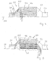
- FIG. 4 shows the cross-sectional side view of a storage catalytic converter 30, wherein, for the sake of simplicity, only one half of the storage catalytic converter is shown on one side of the symmetry line 39.
- An exhaust pipe 31 leads via a diffuser 35 to a region of the storage catalytic converter with flow regions which are formed parallel to one another and flow channels which, starting from the inflow openings 7 facing the diffuser, extend as far as the downstream confuser 37, which in turn flows into a further exhaust pipe 32 empties.
- the flow channels can, for example, have square, circular or even annular cross-sectional areas perpendicular to the exhaust gas flow; in the latter case, the schematic representation is to be interpreted such that for each flow channel only one half of the lateral cross section is always displayed.
- the flow channels 44 are delimited by limiting devices formed as catalytically coated channel walls 46, which, in contrast to the structures depicted in FIGS. 1 to 3, are impermeable to the exhaust gas.
- the lines provided with reference numeral 48 represent flow lines of a flowing exhaust gas, reference numeral 50 denotes whirl lines.
- the cross-sectional areas of the flow channels perpendicular to the main flow direction of the exhaust gas from the exhaust pipe 31 to the exhaust pipe 32 have the same size in the interior of the catalyst as in the edge region of the catalyst. Due to the widening of the flow space in the region of the diffuser, however, marginally exhaust eddies 50 are formed, and the flow channels in the interior of the catalyst are flowed through more than the flow channels lying in the edge region of the catalyst behind the vortex lines 50.
- FIG. 5 shows a modified catalyst device compared to the arrangement according to FIG. Identical or similar components are provided with the same reference numerals as in FIG. 4 and will not be described again.
- the channel walls 46 are covered with layers 53, the thickness of which decreases from the interior of the catalyst near the line of symmetry 39 to the edge region.
- the material of the layers is the same as the material of the channel walls, a catalytically active coating is located instead of on the channel walls 46 on the deposited on the channel walls layers 53.
- the flow lines 55 symbolize the flow of the exhaust gas.
- a first region 57 of low flow resistance is shown by a dashed line and a second region 58 of high flow resistance is shown in the inner region of the catalyst.
- the coating was produced by means of a mask technique, in which in particular the edge regions of a catalyst base body were covered on the end faces before the layers were applied in a dip bath. In the simplest case, some channel walls are coated inside the catalyst, while the channel walls in the edge regions of the catalyst remain uncoated.
- the coating consists of a washcoat coating.
- Thicker layers 53 in the center of the catalyst than in the edge region of the catalyst or layers 53 per se in the center of the catalyst increase the flow resistance in the center of the catalyst compared to the edge region, so that a more uniform flow of all flow channels 4 (the flow resistance in region 58 is higher than in region 57). Due to the decreasing from the center to the edge flow resistance, the flow of the exhaust gas in the edge region compared to the center is just so favored that the existing without coating 53 different flow of the channels with exhaust gas tends to be compensated.
- the catalyst may also be designed as a three-way catalyst, as an oxidation catalyst or as a catalyst for selective catalytic reduction.
- the catalyst base body may also already be manufactured such that the flow channels have a greater flow resistance in the interior of the body than in the edge region. The body then only needs to be uniformly coated with a catalytically active substance, if the body itself is not already contains catalytically active materials.
- the layers 53 may also already contain the catalytically active material. In addition to washcoat coatings, any other possible coating form is also suitable with which a uniform application of material in the flow channels can be achieved.
- the catalyst 30 may also be designed asymmetrically, ie it does not need to have a line of symmetry 39.
Landscapes
- Chemical & Material Sciences (AREA)
- Engineering & Computer Science (AREA)
- Physics & Mathematics (AREA)
- Geometry (AREA)
- Chemical Kinetics & Catalysis (AREA)
- Mechanical Engineering (AREA)
- Combustion & Propulsion (AREA)
- General Engineering & Computer Science (AREA)
- Exhaust Gas After Treatment (AREA)
- Filtering Of Dispersed Particles In Gases (AREA)
- Catalysts (AREA)
- Filtering Materials (AREA)
- Exhaust Gas Treatment By Means Of Catalyst (AREA)
Claims (12)
- Système de post-traitement des gaz d'échappement comportant un organe traversé par les gaz d'échappement d'un moteur à combustion, cet organe ayant des zones d'écoulement (4, 44) séparées les unes des autres et délimitées chacune par une installation de limitation (2, 12, 14, 46), ayant au moins un orifice d'entrée (7) recevant les gaz d'échappement,
les installations de limitation étant perméables aux gaz d'échappement et retenant les particules de suie contenues dans les gaz d'échappement,
caractérisé en ce que
la perméabilité des installations de limitation varie en ce que cette perméabilité d'au moins deux installations de limitation diffère à proximité des orifices d'entrée et/ou dans des zones éloignées des orifices d'entrée de façon à réaliser des zones ayant une résistance à l'écoulement, différente. - Système de post-traitement des gaz d'échappement selon la revendication 1,
caractérisé en ce que
la perméabilité différente des installations de limitation est conditionnée au moins en partie par des épaisseurs sélectionnées de manière appropriée pour les installations de limitation. - Système de post-traitement selon l'une des revendications précédentes,
caractérisé en ce que
les installations de limitation comprennent chacune une paroi et une couche (12, 14, 53) couvrant au moins en partie la paroi, et l'épaisseur de la couche est variable. - Système de post-traitement selon l'une des revendications précédentes,
caractérisé en ce que
la perméabilité d'au moins une installation de limitation dans une zone (11 ; 15) de l'installation de limitation, tournée vers un orifice d'entrée diffère de la perméabilité de l'installation de limitation dans une zone (13 ; 16) éloignée de l'orifice d'entrée. - Système de post-traitement selon l'une des revendications précédentes,
caractérisé en ce que
les installations de limitation sont au moins en partie en matière poreuse, et
la perméabilité différente des installations de limitation est conditionnée au moins en partie par la densité choisie des pores et/ou la dimension des pores dans les zones concernées. - Système de post-traitement selon l'une des revendications précédentes,
caractérisé en ce que
les zones d'écoulement ont des surfaces de section perpendiculaire à la direction d'écoulement des gaz d'échappement et les installations de limitation sont conçues différemment de façon que le contenu des surfaces de section des zones diffère. - Système de post-traitement selon l'une des revendications précédentes,
caractérisé en ce que
le corps traversé par le fluide forme un catalyseur d'oxydation ou un catalyseur accumulateur (30) pour enlever l'azote des gaz d'échappement. - Système de post-traitement selon l'une des revendications précédentes,
caractérisé en ce que
le corps traversé par le fluide forme un filtre à particules. - Système de post-traitement selon l'une des revendications précédentes,
caractérisé en ce que
les installations de limitation sont formées par des parois en céramique. - Système de post-traitement selon l'une des revendications précédentes,
caractérisé en ce que
les installations de limitation sont formées par des tissus métalliques. - Système de post-traitement selon la revendication 10,
caractérisé en ce que
le filtre est un filtre en métal fritté. - Système de post-traitement selon l'une des revendications précédentes,
caractérisé en ce que
les zones de passage de flux sont parallèles de sorte que leurs orifices d'entrée se trouvent d'un côté du corps.
Applications Claiming Priority (3)
| Application Number | Priority Date | Filing Date | Title |
|---|---|---|---|
| DE10247946A DE10247946A1 (de) | 2002-10-15 | 2002-10-15 | Abgasnachbehandlungsanordnung |
| DE10247946 | 2002-10-15 | ||
| PCT/DE2003/002100 WO2004036003A1 (fr) | 2002-10-15 | 2003-06-24 | Systeme de post-traitement de gaz d'echappement |
Publications (2)
| Publication Number | Publication Date |
|---|---|
| EP1554473A1 EP1554473A1 (fr) | 2005-07-20 |
| EP1554473B1 true EP1554473B1 (fr) | 2006-12-20 |
Family
ID=32049262
Family Applications (1)
| Application Number | Title | Priority Date | Filing Date |
|---|---|---|---|
| EP03808663A Expired - Lifetime EP1554473B1 (fr) | 2002-10-15 | 2003-06-24 | Systeme de post-traitement de gaz d'echappement |
Country Status (7)
| Country | Link |
|---|---|
| US (1) | US20060008396A1 (fr) |
| EP (1) | EP1554473B1 (fr) |
| JP (1) | JP2006502842A (fr) |
| KR (1) | KR20050059260A (fr) |
| CN (1) | CN1688799A (fr) |
| DE (2) | DE10247946A1 (fr) |
| WO (1) | WO2004036003A1 (fr) |
Cited By (1)
| Publication number | Priority date | Publication date | Assignee | Title |
|---|---|---|---|---|
| CN106321196A (zh) * | 2016-08-31 | 2017-01-11 | 芜湖恒耀汽车零部件有限公司 | 汽车尾气过滤装置 |
Families Citing this family (27)
| Publication number | Priority date | Publication date | Assignee | Title |
|---|---|---|---|---|
| DE102004012159A1 (de) * | 2004-03-12 | 2005-09-29 | Adam Opel Ag | Monolithischer Katalysator |
| JP2007130624A (ja) * | 2005-10-14 | 2007-05-31 | Matsushita Electric Ind Co Ltd | 排ガス浄化フィルタ |
| US7722827B2 (en) * | 2006-03-31 | 2010-05-25 | Corning Incorporated | Catalytic flow-through fast light off ceramic substrate and method of manufacture |
| FR2918706B1 (fr) * | 2007-07-11 | 2009-10-30 | Peugeot Citroen Automobiles Sa | Dispositif de traitement des emissions gazeuses d'un moteur. |
| US8038954B2 (en) * | 2008-02-14 | 2011-10-18 | Basf Corporation | CSF with low platinum/palladium ratios |
| WO2009118867A1 (fr) | 2008-03-27 | 2009-10-01 | イビデン株式会社 | Structure en nid d'abeilles et appareil de traitement des gaz d'échappement |
| WO2009141890A1 (fr) * | 2008-05-20 | 2009-11-26 | イビデン株式会社 | Structure en nid d'abeille et appareil de purification de gaz d'échappement |
| JP5349108B2 (ja) * | 2009-03-26 | 2013-11-20 | 日本碍子株式会社 | ハニカムフィルタ |
| JP5456353B2 (ja) * | 2009-03-31 | 2014-03-26 | 日本碍子株式会社 | ハニカムフィルタ |
| US8273315B2 (en) * | 2010-08-09 | 2012-09-25 | Ford Global Technologies, Llc | Engine emission control system |
| EP2603320B1 (fr) * | 2010-08-09 | 2016-02-10 | Cormetech, Inc. | Structure catalytique |
| US9724634B2 (en) * | 2012-03-30 | 2017-08-08 | Ibiden Co., Ltd. | Honeycomb filter and method for producing honeycomb filter |
| JP6158832B2 (ja) | 2012-12-03 | 2017-07-05 | トヨタ自動車株式会社 | 排気浄化フィルタ |
| JP6007864B2 (ja) * | 2013-06-10 | 2016-10-12 | トヨタ自動車株式会社 | 排気浄化フィルタ |
| JP2016022397A (ja) * | 2014-07-16 | 2016-02-08 | 住友化学株式会社 | ハニカムフィルタ |
| GB2542654B (en) * | 2015-06-28 | 2019-12-04 | Johnson Matthey Plc | Catalytic wall-flow filter having a membrane |
| GB2546164A (en) * | 2015-09-30 | 2017-07-12 | Johnson Matthey Plc | Gasoline particulate filter |
| GB2545747A (en) * | 2015-12-24 | 2017-06-28 | Johnson Matthey Plc | Gasoline particulate filter |
| DE102017106374A1 (de) | 2016-04-01 | 2017-10-05 | Johnson Matthey Public Limited Company | Abgasreinigungsfilter |
| CN108201749A (zh) * | 2016-12-17 | 2018-06-26 | 重庆市银盛模具有限公司 | 处理废气的结构 |
| JP7037985B2 (ja) * | 2018-03-30 | 2022-03-17 | 日本碍子株式会社 | ハニカムフィルタ |
| DE102019100097B4 (de) | 2019-01-04 | 2021-12-16 | Umicore Ag & Co. Kg | Verfahren zur Herstellung von katalytisch aktiven Wandflussfiltern |
| KR102847669B1 (ko) * | 2020-11-25 | 2025-08-22 | 한국전력공사 | 복합촉매층을 포함하는 디젤분진필터 장치 및 디젤분진필터 장치의 복합촉매층 형성방법 |
| SE545100C2 (en) | 2020-12-03 | 2023-03-28 | Camfil Ab | An air filtration cassette comprising a tapered filter medium with an open interior space, an air filter and a filter arrangement |
| JP7271610B2 (ja) * | 2021-06-17 | 2023-05-11 | 株式会社キャタラー | パティキュレートフィルタ |
| US11772025B1 (en) | 2022-08-02 | 2023-10-03 | W. L. Gore & Associates, Inc. | Industrial filter assembly enhancement |
| EP4424407A1 (fr) * | 2023-02-28 | 2024-09-04 | Umicore AG & Co. KG | Gpf avec distribution de couche d'imprégnation améliorée |
Family Cites Families (3)
| Publication number | Priority date | Publication date | Assignee | Title |
|---|---|---|---|---|
| US4390355A (en) * | 1982-02-02 | 1983-06-28 | General Motors Corporation | Wall-flow monolith filter |
| US4846906A (en) * | 1987-12-02 | 1989-07-11 | The Duriron Company, Inc. | Methods for the manufacture of porous ceramic shapes containing membraneous surfaces |
| JP4427658B2 (ja) * | 1998-07-07 | 2010-03-10 | コーニング インコーポレイテッド | ディーゼル排出ガスフィルター |
-
2002
- 2002-10-15 DE DE10247946A patent/DE10247946A1/de not_active Withdrawn
-
2003
- 2003-06-24 US US10/531,278 patent/US20060008396A1/en not_active Abandoned
- 2003-06-24 DE DE50306063T patent/DE50306063D1/de not_active Expired - Lifetime
- 2003-06-24 CN CNA038243059A patent/CN1688799A/zh active Pending
- 2003-06-24 EP EP03808663A patent/EP1554473B1/fr not_active Expired - Lifetime
- 2003-06-24 WO PCT/DE2003/002100 patent/WO2004036003A1/fr not_active Ceased
- 2003-06-24 JP JP2004543926A patent/JP2006502842A/ja not_active Withdrawn
- 2003-06-24 KR KR1020057006425A patent/KR20050059260A/ko not_active Withdrawn
Cited By (1)
| Publication number | Priority date | Publication date | Assignee | Title |
|---|---|---|---|---|
| CN106321196A (zh) * | 2016-08-31 | 2017-01-11 | 芜湖恒耀汽车零部件有限公司 | 汽车尾气过滤装置 |
Also Published As
| Publication number | Publication date |
|---|---|
| DE50306063D1 (de) | 2007-02-01 |
| EP1554473A1 (fr) | 2005-07-20 |
| DE10247946A1 (de) | 2004-04-29 |
| JP2006502842A (ja) | 2006-01-26 |
| KR20050059260A (ko) | 2005-06-17 |
| WO2004036003A1 (fr) | 2004-04-29 |
| US20060008396A1 (en) | 2006-01-12 |
| CN1688799A (zh) | 2005-10-26 |
Similar Documents
| Publication | Publication Date | Title |
|---|---|---|
| EP1554473B1 (fr) | Systeme de post-traitement de gaz d'echappement | |
| DE60020070T2 (de) | Katalytischer wabenköper-filter mit porösen trennwänden | |
| DE102016111766A1 (de) | Katalytischer wandstromfilter, der eine membran aufweist | |
| DE102017125192A1 (de) | Katalytisches Wandstromfilter mit partieller Oberflächenbeschichtung | |
| DE4005189A1 (de) | Abgasreinigungsvorrichtung fuer einen dieselmotor | |
| DE102020110011A1 (de) | Abgasreinigungsvorrichtung | |
| EP1433519B1 (fr) | Procédé de fabrication d'un filtre à particules avec une fonction de stockage des NOx | |
| DE102015212788A1 (de) | Katalytisch aktives Partikelfilter | |
| DE102005023518B4 (de) | Verstopfungsfreies Filteraggregat mit hohem Wirkungsgrad | |
| DE102005005663A1 (de) | Abgasnachbehandlungseinrichtung mit Partikelfilter | |
| DE102005044494B3 (de) | Vorrichtung zur Beseitigung von schädlichen Bestandteilen aus Abgasen von Brennkraftmaschinen | |
| DE102016225629A1 (de) | Abgassystem und Steuerverfahren von Stickoxiddesorption | |
| DE60212245T2 (de) | Verfahren und Vorrichtung zum Entfernen von Russpartikeln aus dem Abgas eines Dieselmotors | |
| EP2166203B1 (fr) | Dispositif de nettoyage d'un flux de gaz d'échappement d'un moteur à combustion interne d'un véhicule automobile, notamment un véhicule utilitaire | |
| DE102007056213A1 (de) | Verfahren zur Herstellung eines von Abgas durchströmbaren Formkörpers sowie Abgasanlage einer Brennkraftmaschine | |
| WO2015074698A1 (fr) | Filtre à particules configuré sous la forme d'un filtre à parois | |
| DE19961483B4 (de) | Reinigungskatalysator für das Abgas eines Verbrennungsmotors | |
| EP2659950B1 (fr) | Système de traitement postérieur de gaz d'échappement | |
| WO2004047958A2 (fr) | Procede pour appliquer un revetement a action catalytique sur un support de catalyseur presentant deux structures partielles differentes et catalyseur ainsi obtenu | |
| DE102008003044B4 (de) | Abgasreinigungssystem zur verbesserten Abgasreinigung durch konvektives Mischen | |
| WO2009000667A2 (fr) | Élément de catalyseur, catalyseur pour le traitement secondaire des gaz d'échappement d'un moteur à combustion interne et procédé de fabrication d'un élément de catalyseur selon l'invention | |
| WO2005046869A1 (fr) | Systeme d'echappement d'un moteur a combustion interne | |
| EP2699770B1 (fr) | Filtre a particules comprenant un revetement catalytique | |
| EP3582876B1 (fr) | Filtres à particules comprenant des alvéoles d'accumulation de catalyseur | |
| DE102005032954B4 (de) | Partikelfilter für Abgase |
Legal Events
| Date | Code | Title | Description |
|---|---|---|---|
| PUAI | Public reference made under article 153(3) epc to a published international application that has entered the european phase |
Free format text: ORIGINAL CODE: 0009012 |
|
| 17P | Request for examination filed |
Effective date: 20050517 |
|
| AK | Designated contracting states |
Kind code of ref document: A1 Designated state(s): AT BE BG CH CY CZ DE DK EE ES FI FR GB GR HU IE IT LI LU MC NL PT RO SE SI SK TR |
|
| RBV | Designated contracting states (corrected) |
Designated state(s): DE FR GB IT |
|
| GRAP | Despatch of communication of intention to grant a patent |
Free format text: ORIGINAL CODE: EPIDOSNIGR1 |
|
| GRAS | Grant fee paid |
Free format text: ORIGINAL CODE: EPIDOSNIGR3 |
|
| GRAA | (expected) grant |
Free format text: ORIGINAL CODE: 0009210 |
|
| AK | Designated contracting states |
Kind code of ref document: B1 Designated state(s): DE FR GB IT |
|
| REG | Reference to a national code |
Ref country code: GB Ref legal event code: FG4D Free format text: NOT ENGLISH |
|
| REF | Corresponds to: |
Ref document number: 50306063 Country of ref document: DE Date of ref document: 20070201 Kind code of ref document: P |
|
| ET | Fr: translation filed | ||
| PLBE | No opposition filed within time limit |
Free format text: ORIGINAL CODE: 0009261 |
|
| STAA | Information on the status of an ep patent application or granted ep patent |
Free format text: STATUS: NO OPPOSITION FILED WITHIN TIME LIMIT |
|
| 26N | No opposition filed |
Effective date: 20070921 |
|
| PGFP | Annual fee paid to national office [announced via postgrant information from national office to epo] |
Ref country code: GB Payment date: 20120621 Year of fee payment: 10 Ref country code: FR Payment date: 20120705 Year of fee payment: 10 |
|
| PGFP | Annual fee paid to national office [announced via postgrant information from national office to epo] |
Ref country code: IT Payment date: 20120626 Year of fee payment: 10 |
|
| PGFP | Annual fee paid to national office [announced via postgrant information from national office to epo] |
Ref country code: DE Payment date: 20120822 Year of fee payment: 10 |
|
| GBPC | Gb: european patent ceased through non-payment of renewal fee |
Effective date: 20130624 |
|
| REG | Reference to a national code |
Ref country code: DE Ref legal event code: R119 Ref document number: 50306063 Country of ref document: DE Effective date: 20140101 |
|
| REG | Reference to a national code |
Ref country code: FR Ref legal event code: ST Effective date: 20140228 |
|
| PG25 | Lapsed in a contracting state [announced via postgrant information from national office to epo] |
Ref country code: GB Free format text: LAPSE BECAUSE OF NON-PAYMENT OF DUE FEES Effective date: 20130624 Ref country code: DE Free format text: LAPSE BECAUSE OF NON-PAYMENT OF DUE FEES Effective date: 20140101 |
|
| PG25 | Lapsed in a contracting state [announced via postgrant information from national office to epo] |
Ref country code: FR Free format text: LAPSE BECAUSE OF NON-PAYMENT OF DUE FEES Effective date: 20130701 Ref country code: IT Free format text: LAPSE BECAUSE OF NON-PAYMENT OF DUE FEES Effective date: 20130624 |