EP1554474B2 - Installation d'epuration des gaz d'echappement d'un moteur a combustion interne et procede pour epurer ces gaz d'echappement - Google Patents
Installation d'epuration des gaz d'echappement d'un moteur a combustion interne et procede pour epurer ces gaz d'echappement Download PDFInfo
- Publication number
- EP1554474B2 EP1554474B2 EP03808672A EP03808672A EP1554474B2 EP 1554474 B2 EP1554474 B2 EP 1554474B2 EP 03808672 A EP03808672 A EP 03808672A EP 03808672 A EP03808672 A EP 03808672A EP 1554474 B2 EP1554474 B2 EP 1554474B2
- Authority
- EP
- European Patent Office
- Prior art keywords
- exhaust
- catalytic converter
- oxidation catalytic
- internal combustion
- reducing agent
- Prior art date
- Legal status (The legal status is an assumption and is not a legal conclusion. Google has not performed a legal analysis and makes no representation as to the accuracy of the status listed.)
- Expired - Lifetime
Links
Images


Classifications
-
- F—MECHANICAL ENGINEERING; LIGHTING; HEATING; WEAPONS; BLASTING
- F01—MACHINES OR ENGINES IN GENERAL; ENGINE PLANTS IN GENERAL; STEAM ENGINES
- F01N—GAS-FLOW SILENCERS OR EXHAUST APPARATUS FOR MACHINES OR ENGINES IN GENERAL; GAS-FLOW SILENCERS OR EXHAUST APPARATUS FOR INTERNAL-COMBUSTION ENGINES
- F01N3/00—Exhaust or silencing apparatus having means for purifying, rendering innocuous, or otherwise treating exhaust
- F01N3/08—Exhaust or silencing apparatus having means for purifying, rendering innocuous, or otherwise treating exhaust for rendering innocuous
- F01N3/10—Exhaust or silencing apparatus having means for purifying, rendering innocuous, or otherwise treating exhaust for rendering innocuous by thermal or catalytic conversion of noxious components of exhaust
- F01N3/18—Exhaust or silencing apparatus having means for purifying, rendering innocuous, or otherwise treating exhaust for rendering innocuous by thermal or catalytic conversion of noxious components of exhaust characterised by methods of operation; Control
- F01N3/20—Exhaust or silencing apparatus having means for purifying, rendering innocuous, or otherwise treating exhaust for rendering innocuous by thermal or catalytic conversion of noxious components of exhaust characterised by methods of operation; Control specially adapted for catalytic conversion
- F01N3/206—Adding periodically or continuously substances to exhaust gases for promoting purification, e.g. catalytic material in liquid form, NOx reducing agents
- F01N3/2066—Selective catalytic reduction [SCR]
-
- B—PERFORMING OPERATIONS; TRANSPORTING
- B01—PHYSICAL OR CHEMICAL PROCESSES OR APPARATUS IN GENERAL
- B01D—SEPARATION
- B01D53/00—Separation of gases or vapours; Recovering vapours of volatile solvents from gases; Chemical or biological purification of waste gases, e.g. engine exhaust gases, smoke, fumes, flue gases, aerosols
- B01D53/34—Chemical or biological purification of waste gases
- B01D53/74—General processes for purification of waste gases; Apparatus or devices specially adapted therefor
- B01D53/86—Catalytic processes
- B01D53/90—Injecting reactants
-
- B—PERFORMING OPERATIONS; TRANSPORTING
- B01—PHYSICAL OR CHEMICAL PROCESSES OR APPARATUS IN GENERAL
- B01D—SEPARATION
- B01D53/00—Separation of gases or vapours; Recovering vapours of volatile solvents from gases; Chemical or biological purification of waste gases, e.g. engine exhaust gases, smoke, fumes, flue gases, aerosols
- B01D53/34—Chemical or biological purification of waste gases
- B01D53/92—Chemical or biological purification of waste gases of engine exhaust gases
- B01D53/94—Chemical or biological purification of waste gases of engine exhaust gases by catalytic processes
- B01D53/9404—Removing only nitrogen compounds
- B01D53/9409—Nitrogen oxides
- B01D53/9431—Processes characterised by a specific device
-
- F—MECHANICAL ENGINEERING; LIGHTING; HEATING; WEAPONS; BLASTING
- F01—MACHINES OR ENGINES IN GENERAL; ENGINE PLANTS IN GENERAL; STEAM ENGINES
- F01N—GAS-FLOW SILENCERS OR EXHAUST APPARATUS FOR MACHINES OR ENGINES IN GENERAL; GAS-FLOW SILENCERS OR EXHAUST APPARATUS FOR INTERNAL-COMBUSTION ENGINES
- F01N13/00—Exhaust or silencing apparatus characterised by constructional features
- F01N13/009—Exhaust or silencing apparatus characterised by constructional features having two or more separate purifying devices arranged in series
-
- F—MECHANICAL ENGINEERING; LIGHTING; HEATING; WEAPONS; BLASTING
- F01—MACHINES OR ENGINES IN GENERAL; ENGINE PLANTS IN GENERAL; STEAM ENGINES
- F01N—GAS-FLOW SILENCERS OR EXHAUST APPARATUS FOR MACHINES OR ENGINES IN GENERAL; GAS-FLOW SILENCERS OR EXHAUST APPARATUS FOR INTERNAL-COMBUSTION ENGINES
- F01N13/00—Exhaust or silencing apparatus characterised by constructional features
- F01N13/009—Exhaust or silencing apparatus characterised by constructional features having two or more separate purifying devices arranged in series
- F01N13/0097—Exhaust or silencing apparatus characterised by constructional features having two or more separate purifying devices arranged in series the purifying devices are arranged in a single housing
-
- F—MECHANICAL ENGINEERING; LIGHTING; HEATING; WEAPONS; BLASTING
- F01—MACHINES OR ENGINES IN GENERAL; ENGINE PLANTS IN GENERAL; STEAM ENGINES
- F01N—GAS-FLOW SILENCERS OR EXHAUST APPARATUS FOR MACHINES OR ENGINES IN GENERAL; GAS-FLOW SILENCERS OR EXHAUST APPARATUS FOR INTERNAL-COMBUSTION ENGINES
- F01N2610/00—Adding substances to exhaust gases
- F01N2610/02—Adding substances to exhaust gases the substance being ammonia or urea
-
- F—MECHANICAL ENGINEERING; LIGHTING; HEATING; WEAPONS; BLASTING
- F02—COMBUSTION ENGINES; HOT-GAS OR COMBUSTION-PRODUCT ENGINE PLANTS
- F02B—INTERNAL-COMBUSTION PISTON ENGINES; COMBUSTION ENGINES IN GENERAL
- F02B29/00—Engines characterised by provision for charging or scavenging not provided for in groups F02B25/00, F02B27/00 or F02B33/00 - F02B39/00; Details thereof
- F02B29/04—Cooling of air intake supply
- F02B29/0406—Layout of the intake air cooling or coolant circuit
- F02B29/0437—Liquid cooled heat exchangers
-
- F—MECHANICAL ENGINEERING; LIGHTING; HEATING; WEAPONS; BLASTING
- F02—COMBUSTION ENGINES; HOT-GAS OR COMBUSTION-PRODUCT ENGINE PLANTS
- F02B—INTERNAL-COMBUSTION PISTON ENGINES; COMBUSTION ENGINES IN GENERAL
- F02B37/00—Engines characterised by provision of pumps driven at least for part of the time by exhaust
-
- F—MECHANICAL ENGINEERING; LIGHTING; HEATING; WEAPONS; BLASTING
- F02—COMBUSTION ENGINES; HOT-GAS OR COMBUSTION-PRODUCT ENGINE PLANTS
- F02M—SUPPLYING COMBUSTION ENGINES IN GENERAL WITH COMBUSTIBLE MIXTURES OR CONSTITUENTS THEREOF
- F02M26/00—Engine-pertinent apparatus for adding exhaust gases to combustion-air, main fuel or fuel-air mixture, e.g. by exhaust gas recirculation [EGR] systems
- F02M26/02—EGR systems specially adapted for supercharged engines
- F02M26/04—EGR systems specially adapted for supercharged engines with a single turbocharger
- F02M26/05—High pressure loops, i.e. wherein recirculated exhaust gas is taken out from the exhaust system upstream of the turbine and reintroduced into the intake system downstream of the compressor
-
- F—MECHANICAL ENGINEERING; LIGHTING; HEATING; WEAPONS; BLASTING
- F02—COMBUSTION ENGINES; HOT-GAS OR COMBUSTION-PRODUCT ENGINE PLANTS
- F02M—SUPPLYING COMBUSTION ENGINES IN GENERAL WITH COMBUSTIBLE MIXTURES OR CONSTITUENTS THEREOF
- F02M26/00—Engine-pertinent apparatus for adding exhaust gases to combustion-air, main fuel or fuel-air mixture, e.g. by exhaust gas recirculation [EGR] systems
- F02M26/13—Arrangement or layout of EGR passages, e.g. in relation to specific engine parts or for incorporation of accessories
- F02M26/22—Arrangement or layout of EGR passages, e.g. in relation to specific engine parts or for incorporation of accessories with coolers in the recirculation passage
- F02M26/23—Layout, e.g. schematics
-
- Y—GENERAL TAGGING OF NEW TECHNOLOGICAL DEVELOPMENTS; GENERAL TAGGING OF CROSS-SECTIONAL TECHNOLOGIES SPANNING OVER SEVERAL SECTIONS OF THE IPC; TECHNICAL SUBJECTS COVERED BY FORMER USPC CROSS-REFERENCE ART COLLECTIONS [XRACs] AND DIGESTS
- Y02—TECHNOLOGIES OR APPLICATIONS FOR MITIGATION OR ADAPTATION AGAINST CLIMATE CHANGE
- Y02T—CLIMATE CHANGE MITIGATION TECHNOLOGIES RELATED TO TRANSPORTATION
- Y02T10/00—Road transport of goods or passengers
- Y02T10/10—Internal combustion engine [ICE] based vehicles
- Y02T10/12—Improving ICE efficiencies
Definitions
- the invention relates to an exhaust gas purification system of an internal combustion engine with a device for selective catalytic reduction.
- the invention further relates to a method for purifying exhaust gases of an internal combustion engine, in which an exhaust gas stream is passed through a device for selective catalytic reduction.
- a reducing agent is, for example, NH 3 , which can be introduced as a gas in the exhaust stream.
- SCR selective catalytic reduction
- the ammonia is selectively converted into molecular nitrogen and water by the nitrogen oxides contained in the exhaust gas.
- pure ammonia gas is not suitable for use in motor vehicles.
- One known method involves the use of aqueous urea solution as a reducing agent. In this case, the actual reducing agent ammonia is liberated only by thermolysis and subsequent catalyzed hydrolysis of the urea.
- the known SCR systems have an insufficient activity at exhaust gas temperatures below about 250 ° C.
- An upstream connection of an oxidation catalyst on the one hand ensures a reduction in the proportions of deactivating hydrocarbons and on the other hand for an oxidation of NO to NO 2 , which leads to a significant increase in overall NO x conversion at exhaust gas temperatures above about 200 ° C.
- Below about 180 ° C the system offers due to the relatively long decomposition time of urea to NH 3, an insufficient activity.
- phases with such low exhaust gas temperatures occur relatively frequently, which illustrates an average catalyst temperature of less than 180 ° C. in the so-called MVEG test cycle.
- a mixing section of about 40 cm may be provided, which is optionally provided with a mixing device.
- a mixing device for an emission control system is in the earlier German patent application with the file number 101 31 803.0 described.
- a mixing body arranged in the exhaust pipe has a gas impingement surface and a jet impingement surface so that reducing agent flowing from the internal combustion engine can impinge on the gas impingement surface and on the jet impact surface which can be supplied to the exhaust gas flow.
- the EP 1174599 describes a filter assembly with incorporated therein catalyst films, wherein a part of the films has an oxidation-catalytic effect and another part of the film has a nitrogen-reducing effect. Both types of catalyst sheets are loaded with dosing agent.
- the EP 1052009 describes methods for the thermal hydrolysis and metering of urea or an aqueous urea solution in which the hydrolysis takes place in a hydrolysis reactor arranged upstream of an SCR catalyst.
- an exhaust gas purification system for cleaning the exhaust gas of an internal combustion engine, at least one arranged in an exhaust passage of the internal combustion engine oxidation catalyst and at least one arranged behind this device for selective catalytic reduction (SCR catalyst) is provided.
- a feed device integrated in the at least one oxidation catalytic converter is provided for feeding a reducing agent into the exhaust gas flow of the internal combustion engine.
- the mixing distance of about 40 cm which is usually necessary for a good distribution of the reducing agent on the SCR catalyst, can be significantly reduced without an undesirable pressure drop occurring in the system. Due to the omission of the usually required long mixing section, the SCR catalytic converter does not necessarily have to be installed in the underbody area of the vehicle, but can optionally be moved closer to the exhaust gas outlet of the internal combustion engine. In this way, a more favorable temperature profile results in the emission control system, which has an advantageous effect on the cleaning effect.
- the injection of the reducing agent is advantageously carried out directly in the oxidation catalyst.
- a recess or bore of the oxidation catalyst is necessary because the reducing agent should not come into contact with the oxidation catalyst as possible, otherwise an undesired oxidation to molecular nitrogen, nitrogen dioxide or nitrogen monoxide can take place.
- An embodiment of the invention provides that the feed device has a nozzle for atomizing the reducing agent.
- One embodiment of the invention provides a mixing device arranged downstream of the feed device for better distribution of the reducing agent in the exhaust gas stream. In this way, an even better mixing of the reducing agent with the exhaust gas stream and thus an even better cleaning effect of the exhaust gas in the following SCR catalyst can be achieved.
- the exit of the nozzle may optionally be arranged approximately centrally or off-center in the oxidation catalyst.
- An off-center injection can for example be done with a lateral twist, so that nevertheless a good mixing with the exhaust gas flow is ensured.
- the oxidation catalyst can optionally not be recessed over its entire length, but only downstream of the injection point.
- the thermal reductant beneficiation benefits from the exothermicity of the oxidation catalyst, which occurs due to the oxidation of hydrocarbons and carbon monoxide.
- An embodiment according to the invention provides that the at least one oxidation catalytic converter with the reducing agent supply device integrated therein has a first housing and that the selective catalytic reduction device has an adjoining second housing. Between the two housings a connecting tube is preferably provided, which may have a different length depending on the structural conditions in the vehicle. Preferably, however, the connecting tube is designed as short as possible in order to prevent cooling of the exhaust gas flow as far as possible before reaching the device for selective catalytic reduction.
- the cleaning effect of the SCR catalyst reaches only at temperatures of about 300 ° C satisfactory orders of magnitude.
- An alternative embodiment provides that the at least one oxidation catalytic converter and the device for selective catalytic reduction have a common housing. This ensures that the exhaust gas flow subjected to reducing agent has an ideal temperature for conversion and NO x reduction in the SCR catalytic converter. Overall, the structural integrity of the two components ensures a compact design and a favorable emission control effect.
- a preferred embodiment of the invention provides that at least one further oxidation catalytic converter is arranged upstream of the at least one oxidation catalytic converter in the exhaust gas stream of the internal combustion engine.
- the at least one oxidation catalytic converter is preferably arranged in the immediate vicinity of the combustion chambers of the internal combustion engine and can, for example, in each case consist of a further oxidation catalytic converter at each exhaust gas outlet of each combustion chamber of the internal combustion engine.
- the SCR catalyst can be largely protected against occupancy with hydrocarbons and carbon monoxide.
- the additional near-engine oxidation catalysts which can also be referred to as cylinder head or pre-turbocharger catalysts, provide for a large extent. Implementation of the hydrocarbons contained in the exhaust gas and the carbon monoxide and thus significantly improve the cleaning effect of the SCR catalyst.
- the pre-catalysts may preferably be arranged in front of an exhaust gas turbine of an exhaust gas turbocharger.
- Suitable reducing agents are preferably all ammonia-containing or ammonia-releasing substances, for example HWL, ammonium carbamate, ammonia gas, etc.
- a method for purifying exhaust gases of an internal combustion engine, in particular an internal combustion engine with auto-ignition and / or direct fuel injection, in which an exhaust gas flow through at least one arranged in the exhaust gas oxidation catalyst and at least one of these downstream selective catalytic reduction device (SCR catalyst) is directed sees
- a reducing agent is supplied to the exhaust gas stream within the at least one oxidation catalyst. Due to the injection of the reducing agent at the beginning of the catalyst section eliminates the previously required mixing section. Even without the mixing section, an optimal admission of the following SCR catalyst is ensured, since the reducing agent is ideally mixed by passing the two transition funnel of the exhaust system with the exhaust stream. This makes it possible to significantly reduce the overall length of the system and to accelerate the heating of the catalysts. Furthermore, this allows a relatively close-coupled installation of the SCR catalyst, so that the catalyst can possibly be accommodated in the engine compartment and can account for the unfavorable to achieve a fast working temperature installation position in the underbody area of the vehicle.
- An embodiment of the method provides that the supply and / or atomization of the reducing agent by means of a nozzle which is arranged approximately centrally or optionally off-center within the oxidation catalyst and which ensures a fine distribution of the reducing agent in the oxidation catalyst.
- the preparation of the reducing agent corresponds to a side or
- Partial flow arrangement The spray cone of the injection can be kept substantially smaller than in previously known systems, which is advantageous for the reactions taking place in the catalysts.
- the injection point is much closer to the engine and the reducing agent is thereby better preconditioned for the hydrolysis on the SCR catalyst. This may be of crucial importance, especially at low catalyst temperatures.
- the size of the oxidation catalyst through the recess of the dosing slightly lower, which reduces the risk of the occurrence of high NO 2 levels especially at temperatures around 300 ° C in conjunction with low exhaust gas velocities.
- the slightly smaller size has hardly any negative influence on the NO 2 content during cold start or at low catalyst temperatures (low engine load).
- FIG. 1 shows a schematic representation of an internal combustion engine 2 with an inlet channel 21 for supplying fresh gas 22 and with an exhaust duct 29 with disposed therein exhaust gas purification elements.
- a charge air cooler 23 is arranged, which is not absolutely necessary.
- an optional exhaust gas recirculation system 24 is provided between intake passage 21 and exhaust passage 29.
- the internal combustion engine has an exhaust gas turbocharger 25, which has an exhaust gas turbine 26 in the exhaust gas duct, which is coupled via a shaft 27 to a compressor 28 in the inlet duct 21.
- An outlet of each combustion chamber of the internal combustion engine 2 has an outlet channel 30, which are brought together in a subsequent collector 31 to the common exhaust duct 29.
- an oxidation catalyst 4 is provided, which is followed by a device for selective catalytic reduction 8.
- This selective catalytic reduction device is also referred to below as an SCR catalyst.
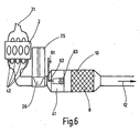
- a connecting tube 44 is provided, which may be omitted if necessary (see. FIG. 6 ), so that oxidation catalyst 4 and SCR catalyst 8 can be accommodated in a common housing.
- An exhaust gas flow 32 polluted with pollutants leaves the SCR catalytic converter as largely purified exhaust gas 12, then preferably passes through a silencer and is led out into the open air.
- oxidation catalyst 4 and SCR catalyst 8 are sometimes referred to as VR system, where the "V” denotes a precatalyst and the "R” the SCR catalyst.
- V denotes a precatalyst
- R the SCR catalyst.
- NO + 1 ⁇ 2 O 2 ⁇ NO 2 the following oxidation reaction takes place: NO + 1 ⁇ 2 O 2 ⁇ NO 2 .
- the SCR catalyst may optionally be preceded by a urea decomposition catalyst ("H") in which the following reaction takes place: (NH 2 ) 2 CO + H 2 O ⁇ 2 NH 3 + CO 2 .
- H urea decomposition catalyst
- the SCR catalyst may optionally be followed by another oxidation catalyst ("O") in which the following reaction takes place: 2 NH 3 + 3/2 O 2 ⁇ N 2 + 3 H 2 O.
- O oxidation catalyst
- VHRO systems The systems modified by an oxidation catalyst are commonly referred to as VHRO systems, whereby the individual components are designated in their order.
- the use of the oxidation catalyst ("O") acting as NH 3 blocking catalyst behind the SCR catalyst is also optional.
- the invention is described with reference to the simplified VR system, which can optionally be supplemented by the mentioned components to the VHRO system.
- a supply means 6 for supplying reducing agent 61 is provided in the exhaust gas stream 32, which will be described below with reference to FIGS. 2 to 6 is explained in more detail.
- the embodiments of the invention are described, according to the invention, the task of accelerating the decomposition of urea is taken over by the SCR catalyst.
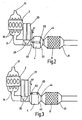
- FIG. 2 shows a first embodiment of the emission control system according to the invention, in which in the oxidation catalyst 4 in approximately central position, a nozzle 62 is arranged, by means of which the reducing agent 61 atomized into the oxidation catalyst 4 and in this way the exhaust gas stream 32 is supplied. Behind the nozzle 62, in the spray cone or slightly behind it, a mixing device 63 may be provided, which, however, may optionally be omitted. After passing through a connecting pipe 44, the exhaust gases enter the SCR catalytic converter 8, in which the nitrogen oxides are converted to molecular nitrogen with the addition of NH 3 and water.
- FIG. 3 shows an alternative embodiment of the arrangement of the nozzle 62, which is located off-center in the oxidation catalyst 4.
- the mixing device 63 is also located off-center in the oxidation catalyst 4, so that a thorough mixing of the reducing agent 61 in the exhaust gas stream 32 can take place.
- FIG. 4 shows a further alternative embodiment of the exhaust gas cleaning system according to the invention, in which each of the exhaust ports 30 of the internal combustion engine 2 individual oxidation catalysts are arranged, which are referred to here as second oxidation catalysts 42.
- These second oxidation catalytic converters 42 are known as so-called cylinder head or pre-turbocharger catalytic converters and ensure that the SCR catalytic converter 8 is largely protected from being contaminated with hydrocarbons and carbon monoxide.
- the arrangement of the feed device 6 with the centrally arranged in the first oxidation catalyst 41 nozzle 62 largely corresponds to the embodiment according to FIG. 2 ,
- FIG. 5 shows a corresponding arrangement of the second oxidation catalysts 42 in the exhaust ports 30 of the internal combustion engine 2, as in the embodiment according to FIG. 4 is provided.
- the off-center arrangement of the feed device 6 with the nozzle 62 and the optional mixing device corresponds to the embodiment according to FIG FIG. 3 ,
- the first oxidation catalytic converter 4 or 41 is arranged in a housing 43 which is separated from a housing 81 of the SCR catalytic converter 8 by a connecting tube 44.
- the embodiment of the emission control system according to FIG. 6 shows an integrated housing 10, in which along the exhaust gas flow of the first oxidation catalyst 41 and downstream of the SCR catalyst 8 is arranged.
- This design leads to an extremely compact emission control system, which also causes a very effective emission control, as the exhaust gases remain at a high temperature level due to the omitted connecting pipe.
- the second oxidation catalysts in the exhaust ducts 30 of the internal combustion engine can optionally also be omitted in this embodiment with the integrated housing 10 (cf. FIGS. 2 and 3 ).
Landscapes
- Engineering & Computer Science (AREA)
- Chemical & Material Sciences (AREA)
- Chemical Kinetics & Catalysis (AREA)
- Combustion & Propulsion (AREA)
- Health & Medical Sciences (AREA)
- Environmental & Geological Engineering (AREA)
- Mechanical Engineering (AREA)
- General Engineering & Computer Science (AREA)
- Analytical Chemistry (AREA)
- General Chemical & Material Sciences (AREA)
- Oil, Petroleum & Natural Gas (AREA)
- Biomedical Technology (AREA)
- Toxicology (AREA)
- Exhaust Gas After Treatment (AREA)
Claims (16)
- Système d'épuration des gaz d'échappement qui épure les gaz d'échappement d'un moteur à combustion interne, en particulier d'un moteur à combustion interne à auto-allumage et/ou à injection directe de carburant,
qui présente au moins un catalyseur d'oxydation disposé dans un canal de gaz d'échappement du moteur à combustion interne et au moins un dispositif de réduction catalytique sélective des gaz d'échappement disposé en aval du catalyseur d'oxydation,
caractérisé en ce que
un dispositif d'amenée (6) est intégré dans le ou les catalyseurs d'oxydation (4) et amène un agent de réduction (61) dans l'écoulement (32) de gaz d'échappement du moteur à combustion interne (2),
en ce que le dispositif d'amenée comprend une découpe ou un alésage ménagés dans le catalyseur d'oxydation de telle sorte que l'agent de réduction puisse aboutir dans l'écoulement de gaz d'échappement sans entrer en contact avec le catalyseur d'oxydation,
en ce qu'au cas où l'on utilise un agent de réduction qui contient de l'urée, la décomposition accélérée de l'urée a lieu dans le dispositif de réduction catalytique sélective en aval de la découpe ou de l'alésage et
en ce que l'emplacement d'injection du dispositif d'amenée est disposé à proximité du moteur. - Système d'épuration des gaz d'échappement selon la revendication 1, caractérisé en ce que le dispositif d'amenée (6) présente une tuyère (62) de pulvérisation de l'agent de réduction.
- Système d'épuration des gaz d'échappement selon les revendications 1 ou 2, caractérisé par un dispositif de mélange (63) disposé en aval du dispositif d'amenée (6) et destiné à répartir l'agent de réduction (61) dans l'écoulement (32) du gaz d'échappement.
- Système d'épuration des gaz d'échappement selon les revendications 2 ou 3, caractérisé en ce qu'une sortie de la tuyère (62) est disposée sensiblement au milieu du catalyseur d'oxydation (4).
- Système d'épuration des gaz d'échappement selon les revendications 2 ou 3, caractérisé en ce que la sortie de la tuyère (62) est disposée dans une bordure extérieure du catalyseur d'oxydation (4).
- Système d'épuration des gaz d'échappement selon l'une des revendications précédentes, caractérisé en ce que le ou les catalyseurs d'oxydation (4) dans lesquels est intégré le dispositif d'amenée (6) présentent un premier boîtier (43) et en ce que le dispositif de réduction catalytique sélective (8) présente un deuxième boîtier (41) qui se raccorde au premier.
- Système d'épuration des gaz d'échappement selon les revendications 1 à 5, caractérisé en ce que le ou les catalyseurs d'oxydation (4) et le dispositif de réduction catalytique sélective (8) présentent un boîtier (10) commun.
- Système d'épuration des gaz d'échappement selon l'une des revendications précédentes, caractérisé en ce qu'au moins un autre catalyseur d'oxydation (41) est disposé en amont du ou des catalyseurs d'oxydation (4) dans l'écoulement (32) du gaz d'échappement du moteur à combustion interne (2).
- Système d'épuration des gaz d'échappement selon la revendication 8, caractérisé en ce que le ou les autres catalyseurs d'oxydation (41) sont disposés à proximité immédiate des chambres de combustion du moteur à combustion interne (2).
- Système d'épuration des gaz d'échappement selon les revendications 8 ou 9, caractérisé par la présence d'au moins un autre catalyseur d'oxydation (41) sur chaque orifice de sortie (29) de gaz d'échappement de chaque chambre de combustion du moteur à combustion interne (2).
- Procédé d'épuration des gaz d'échappement d'un moteur à combustion interne, en particulier d'un moteur à combustion interne à auto-allumage et/ou doté d'une injection directe du carburant, dans lequel un écoulement de gaz d'échappement est amené à travers au moins un catalyseur d'oxydation disposé dans le canal de gaz d'échappement et au moins un dispositif de réduction catalytique sélective raccordé en aval du catalyseur d'oxydation,
caractérisé en ce que
un agent de réduction (61) est amené dans l'écoulement (32) du gaz d'échappement à l'intérieur du ou des catalyseurs d'oxydation (4), l'amenée s'effectuant à l'intérieur du catalyseur d'oxydation de telle sorte que l'agent de réduction puisse aboutir dans l'écoulement de gaz d'échappement par une découpe ou un alésage ménagés dans le catalyseur d'oxydation sans entrer en contact avec le catalyseur d'oxydation,
en ce qu'au cas où on utilise un agent de réduction qui contient de l'urée, la décomposition accélérée de l'urée a lieu dans le dispositif de réduction catalytique sélective en aval de la découpe ou de l'alésage et
en ce que l'emplacement d'injection du dispositif d'amenée est disposé à proximité du moteur. - Procédé selon la revendication 11, caractérisé par une amenée et/ou une pulvérisation de l'agent de réduction (61) au moyen d'une tuyère (62).
- Procédé selon les revendications 11 ou 12, caractérisé en ce que l'amenée d'agent de réduction (61) s'effectue sensiblement au milieu du catalyseur d'oxydation (4).
- Procédé selon les revendications 11 ou 12, caractérisé en ce que l'amenée de l'agent de réduction (61) s'effectue à distance du centre du catalyseur d'oxydation (4).
- Procédé selon l'une des revendications 11 à 14,-caractérisé en ce que l'écoulement (32) de gaz d'échappement est passé dans au moins un autre catalyseur d'oxydation (41) situé en amont du premier catalyseur d'oxydation (4).
- Procédé selon l'une des revendications 11 à 15, caractérisé en ce que l'écoulement (32) de gaz d'échappement est passé dans au moins un autre catalyseur d'oxydation (41) prévu dans chaque canal (29) de gaz d'échappement immédiatement en aval des chambres de combustion du moteur à combustion interne (2).
Applications Claiming Priority (3)
| Application Number | Priority Date | Filing Date | Title |
|---|---|---|---|
| DE10247989 | 2002-10-15 | ||
| DE10247989A DE10247989A1 (de) | 2002-10-15 | 2002-10-15 | Abgasreinigung einer Brennkraftmaschine und Verfahren zur Reinigung deren Abgase |
| PCT/DE2003/003196 WO2004036005A2 (fr) | 2002-10-15 | 2003-09-25 | Installation d'epuration des gaz d'echappement d'un moteur a combustion interne et procede pour epurer ces gaz d'echappement |
Publications (3)
| Publication Number | Publication Date |
|---|---|
| EP1554474A2 EP1554474A2 (fr) | 2005-07-20 |
| EP1554474B1 EP1554474B1 (fr) | 2006-08-23 |
| EP1554474B2 true EP1554474B2 (fr) | 2009-11-18 |
Family
ID=32049277
Family Applications (1)
| Application Number | Title | Priority Date | Filing Date |
|---|---|---|---|
| EP03808672A Expired - Lifetime EP1554474B2 (fr) | 2002-10-15 | 2003-09-25 | Installation d'epuration des gaz d'echappement d'un moteur a combustion interne et procede pour epurer ces gaz d'echappement |
Country Status (5)
| Country | Link |
|---|---|
| US (1) | US7200989B2 (fr) |
| EP (1) | EP1554474B2 (fr) |
| JP (1) | JP4445866B2 (fr) |
| DE (2) | DE10247989A1 (fr) |
| WO (1) | WO2004036005A2 (fr) |
Cited By (1)
| Publication number | Priority date | Publication date | Assignee | Title |
|---|---|---|---|---|
| CN104121071A (zh) * | 2013-04-28 | 2014-10-29 | 常州市利众环保科技有限公司 | 汽车尾气循环燃烧绿色排放 |
Families Citing this family (22)
| Publication number | Priority date | Publication date | Assignee | Title |
|---|---|---|---|---|
| DE102006003786A1 (de) * | 2005-09-26 | 2007-04-05 | Faurecia Abgastechnik Gmbh | Abgasanlage mit Einspritzdüse |
| DE102006004170A1 (de) * | 2006-01-27 | 2007-08-02 | Pierburg Gmbh | Vorrichtung zur Reduktion von Stickoxiden im Abgas von Brennkraftmaschinen |
| EP2010762B1 (fr) * | 2006-04-13 | 2016-09-28 | Mack Trucks, Inc. | Moteur équipé d'une dispositif de lutte contre les émissions et procédé pour lutter contre les émissions du moteur |
| JP2008127997A (ja) * | 2006-11-16 | 2008-06-05 | Mitsubishi Fuso Truck & Bus Corp | 内燃機関の排気浄化装置 |
| JP4592816B2 (ja) * | 2007-05-03 | 2010-12-08 | エムエーエヌ・ディーゼル・アンド・ターボ・フィリアル・アフ・エムエーエヌ・ディーゼル・アンド・ターボ・エスイー・ティスクランド | Scr反応器を備える大型ターボ過給型ディーゼルエンジン |
| WO2008144385A2 (fr) * | 2007-05-15 | 2008-11-27 | Donaldson Company, Inc. | Dispositif d'écoulement de gaz d'échappement |
| JP4949152B2 (ja) * | 2007-07-20 | 2012-06-06 | 三菱ふそうトラック・バス株式会社 | 内燃機関の排気浄化装置 |
| JP4949151B2 (ja) * | 2007-07-20 | 2012-06-06 | 三菱ふそうトラック・バス株式会社 | 内燃機関の排気浄化装置 |
| US20090094966A1 (en) * | 2007-10-15 | 2009-04-16 | International Engine Intellectual Property Company, Llc | Aftertreatment device |
| JP2011012564A (ja) * | 2009-06-30 | 2011-01-20 | Toyota Industries Corp | 排気ガス浄化装置 |
| US8347611B2 (en) | 2009-12-23 | 2013-01-08 | Ford Global Technologies, Llc | Methods and systems for emission system control |
| US8347609B2 (en) | 2009-12-23 | 2013-01-08 | Ford Global Technologies, Llc | Methods and systems for emission system control |
| US8516799B2 (en) | 2009-12-23 | 2013-08-27 | Ford Global Technologies, Llc | Methods and systems for emission system control |
| US8096125B2 (en) | 2009-12-23 | 2012-01-17 | Ford Global Technologies, Llc | Methods and systems for emission system control |
| WO2011087527A1 (fr) | 2010-01-12 | 2011-07-21 | Donaldson Company, Inc. | Dispositif d'écoulement pour système de traitement de gaz d'échappement |
| US8042527B2 (en) | 2010-08-05 | 2011-10-25 | Ford Global Technologies, Llc | Coordination of HP and LP EGR |
| JP5609795B2 (ja) * | 2011-07-12 | 2014-10-22 | 株式会社デンソー | 車両用過給装置 |
| DE102011115328A1 (de) * | 2011-10-07 | 2013-04-11 | Mtu Friedrichshafen Gmbh | Verfahren zum Überwachen einer Abgasanlage |
| DE102012010991A1 (de) | 2012-06-02 | 2013-12-05 | Volkswagen Aktiengesellschaft | Verfahren zum Betreiben einer Reduktionsmitteldosierung eines SCR-Katalysatorsystems sowie SCR-Katalysatorsystem |
| JP2015110928A (ja) * | 2013-12-06 | 2015-06-18 | 株式会社日本自動車部品総合研究所 | 排気ガス浄化装置 |
| CN105944569A (zh) * | 2016-06-30 | 2016-09-21 | 山西都宝清洁能源投资有限公司 | 一种强化烟气脱硝工艺方法 |
| DE102017219570A1 (de) | 2017-11-03 | 2019-05-09 | Robert Bosch Gmbh | Abgasstrang für einen Verbrennungsmotor und Verfahren des Betreibens eines Verbrennungsmotors |
Citations (4)
| Publication number | Priority date | Publication date | Assignee | Title |
|---|---|---|---|---|
| DE19755703A1 (de) † | 1997-12-15 | 1999-06-17 | Emitec Emissionstechnologie | Katalysatorträgeranordnung für einen motornahen Einbau |
| EP1052009A1 (fr) † | 1999-03-25 | 2000-11-15 | Man Nutzfahrzeuge Ag | Procédé pour traiter les gaz d'échappement d' un moteur à combustion interne en utilisant de l'uree |
| DE10020170C1 (de) † | 2000-04-25 | 2001-09-06 | Emitec Emissionstechnologie | Verfahren zum Entfernen von Rußpartikeln aus einem Abgas und zugehöriges Auffangelement |
| WO2002043837A1 (fr) † | 2000-12-01 | 2002-06-06 | Fuel Tech, Inc. | Reduction catalytique selective de nox par decomposition d'un courant secondaire d'uree |
Family Cites Families (16)
| Publication number | Priority date | Publication date | Assignee | Title |
|---|---|---|---|---|
| JPH05106430A (ja) * | 1991-10-16 | 1993-04-27 | Toyota Central Res & Dev Lab Inc | 内燃機関の窒素酸化物低減装置 |
| DE4315278A1 (de) * | 1993-05-07 | 1994-11-10 | Siemens Ag | Verfahren und Einrichtung zur Dosierung eines Reduktionsmittels in ein stickoxidhaltiges Abgas |
| JPH07100335A (ja) * | 1993-10-01 | 1995-04-18 | Nippon Oil Co Ltd | 窒素酸化物の除去方法 |
| US5611198A (en) * | 1994-08-16 | 1997-03-18 | Caterpillar Inc. | Series combination catalytic converter |
| DE19546482A1 (de) * | 1995-12-13 | 1997-06-26 | Basf Ag | Verfahren zum Betreiben einer Reinigungsanlage, eine Reinigungsanlage und eine Verwendung derselben |
| DE19731865C2 (de) * | 1997-07-24 | 1999-05-06 | Siemens Ag | Abgasreinigungsanlage für das Abgas eines Dieselmotors |
| DE19740702C1 (de) * | 1997-09-16 | 1998-11-19 | Siemens Ag | Verfahren und Vorrichtung zum Betrieb einer mit Luftüberschuß arbeitenden Brennkraftmaschine |
| DE19902207A1 (de) * | 1999-01-21 | 2000-07-27 | Man Nutzfahrzeuge Ag | Verfahren zur Dosierung eines Reduktionsmittels, sowie Vorrichtung zur Durchführung des Verfahrens |
| US6293096B1 (en) * | 1999-06-23 | 2001-09-25 | Southwest Research Institute | Multiple stage aftertreatment system |
| US6293097B1 (en) * | 1999-08-16 | 2001-09-25 | Ford Global Technologies, Inc. | On-board reductant delivery system |
| US6314722B1 (en) * | 1999-10-06 | 2001-11-13 | Matros Technologies, Inc. | Method and apparatus for emission control |
| DE10035544B4 (de) | 2000-07-21 | 2012-01-05 | Daimler Ag | Filteranordnung für eine Abgasreinigungsanlage |
| DE10059427A1 (de) * | 2000-11-30 | 2002-06-06 | Bosch Gmbh Robert | Einrichtung und Verfahren zur Nachbehandlung von Abgasen |
| DE10130054B4 (de) * | 2001-06-21 | 2014-05-28 | Volkswagen Ag | Abgasanlage einer mehrzylindrigen Verbrennungskraftmaschine und Verfahren zur Reinigung eines Abgases |
| US6449947B1 (en) * | 2001-10-17 | 2002-09-17 | Fleetguard, Inc. | Low pressure injection and turbulent mixing in selective catalytic reduction system |
| WO2004046514A1 (fr) * | 2002-11-15 | 2004-06-03 | Catalytica Energy Systems, Inc. | Dispositifs et procedes pour reduire les emissions de nox de moteurs a melange pauvre |
-
2002
- 2002-10-15 DE DE10247989A patent/DE10247989A1/de not_active Withdrawn
-
2003
- 2003-09-25 US US10/527,584 patent/US7200989B2/en not_active Expired - Fee Related
- 2003-09-25 JP JP2004543947A patent/JP4445866B2/ja not_active Expired - Fee Related
- 2003-09-25 EP EP03808672A patent/EP1554474B2/fr not_active Expired - Lifetime
- 2003-09-25 DE DE50304782T patent/DE50304782D1/de not_active Expired - Lifetime
- 2003-09-25 WO PCT/DE2003/003196 patent/WO2004036005A2/fr not_active Ceased
Patent Citations (4)
| Publication number | Priority date | Publication date | Assignee | Title |
|---|---|---|---|---|
| DE19755703A1 (de) † | 1997-12-15 | 1999-06-17 | Emitec Emissionstechnologie | Katalysatorträgeranordnung für einen motornahen Einbau |
| EP1052009A1 (fr) † | 1999-03-25 | 2000-11-15 | Man Nutzfahrzeuge Ag | Procédé pour traiter les gaz d'échappement d' un moteur à combustion interne en utilisant de l'uree |
| DE10020170C1 (de) † | 2000-04-25 | 2001-09-06 | Emitec Emissionstechnologie | Verfahren zum Entfernen von Rußpartikeln aus einem Abgas und zugehöriges Auffangelement |
| WO2002043837A1 (fr) † | 2000-12-01 | 2002-06-06 | Fuel Tech, Inc. | Reduction catalytique selective de nox par decomposition d'un courant secondaire d'uree |
Cited By (2)
| Publication number | Priority date | Publication date | Assignee | Title |
|---|---|---|---|---|
| CN104121071A (zh) * | 2013-04-28 | 2014-10-29 | 常州市利众环保科技有限公司 | 汽车尾气循环燃烧绿色排放 |
| CN104121071B (zh) * | 2013-04-28 | 2019-01-29 | 常州市利众环保科技有限公司 | 一种汽车尾气循环燃烧绿色排放方法 |
Also Published As
| Publication number | Publication date |
|---|---|
| WO2004036005A3 (fr) | 2004-08-05 |
| US7200989B2 (en) | 2007-04-10 |
| US20060053773A1 (en) | 2006-03-16 |
| EP1554474B1 (fr) | 2006-08-23 |
| JP4445866B2 (ja) | 2010-04-07 |
| EP1554474A2 (fr) | 2005-07-20 |
| DE50304782D1 (de) | 2006-10-05 |
| JP2006503208A (ja) | 2006-01-26 |
| WO2004036005A2 (fr) | 2004-04-29 |
| DE10247989A1 (de) | 2004-04-29 |
Similar Documents
| Publication | Publication Date | Title |
|---|---|---|
| EP1554474B1 (fr) | Installation d'epuration des gaz d'echappement d'un moteur a combustion interne et procede pour epurer ces gaz d'echappement | |
| EP2691618B1 (fr) | Unité de traitement de gaz d'échappement compacte comprenant une zone de mélange et procédé pour mélanger des gaz d'échappement | |
| EP1892395B1 (fr) | Système de traitement de gaz d'échappement | |
| DE102014103678B4 (de) | Kompaktes abgasbehandlungssystem für einen dieselmotor | |
| EP0852512B1 (fr) | Procede et dispositif pour la decomposition des oxydes d'azote contenus dans les gaz d'echappement d'un moteur a combustion interne | |
| EP2266681B1 (fr) | Installation de gaz d'échappement dotée d'une amenée de moyen de réduction et d'un élément de filtre avec un catalyseur SCR | |
| EP2568137B1 (fr) | Système d'injection chauffé pour systèmes de gaz d'échappement de moteurs diesel | |
| DE102009053950A1 (de) | Vorrichtung zur Nachbehandlung von Abgasen von Brennkraftmaschinen | |
| EP1892394A1 (fr) | Système de traitement postérieur de gaz d'échappement | |
| EP1900916A2 (fr) | Système de traitement postérieur de gaz d'échappement | |
| EP2101049A2 (fr) | Système de post-traitement de gaz d'échappement compact | |
| DE102010021438A1 (de) | Abgasnachbehandlungsvorrichtung | |
| DE102009038835A1 (de) | Abgasreinigungsanlage für eine Brennkraftmaschine | |
| DE10243270A1 (de) | Abgasreinigungsanlage einer Brennkraftmaschine und Verfahren zur Reinigung deren Abgase | |
| DE10324013A1 (de) | Vorrichtung zur Reinigung des Abgases einer Brennkraftmaschine und Verfahren hierzu | |
| EP2811130B1 (fr) | Procédé et dispositif de désulfuration de reflux de gaz d'échappement | |
| DE102008048428A1 (de) | Vorrichtung und Verfahren zur Reinigung eines Abgasstroms einer Brennkraftmaschine, insbesondere einer magerlauffähigen Brennkraftmaschine | |
| DE102014221322A1 (de) | Abgasbehandlungseinrichtung für eine Abgasanlage einer Brennkraftmaschine | |
| DE102017118214A1 (de) | Abgasnachbehandlungssystem sowie Verfahren zur Abgasnachbehandlung eines Verbrennungsmotors | |
| DE102018127643A1 (de) | Abgasnachbehandlungssystem und Verfahren zur Abgasnachbehandlung eines Verbrennungsmotors | |
| EP1859131B1 (fr) | Procede de traitement secondaire des gaz d'echappement de moteurs diesel ou analogues et dispositif permettant la mise en oeuvre dudit procede | |
| DE102013225256B4 (de) | Fahrzeug | |
| EP1957767B1 (fr) | Procede de traitement final des gaz d'echappement de moteurs a combustion interne et dispositif en vue de la mise en oeuvre du procede | |
| EP3428414B1 (fr) | Dispositif et procédé pour systèmes de purification des gaz d'échappement des véhicules diesel, en particulier destinés à la mise à niveau des véhicules diesel pourvus de filtre à particules diesel, en particulier pour un mode de conduite urbain | |
| EP2573340B1 (fr) | Installation de gaz d'échappement pour moteur à combustion interne |
Legal Events
| Date | Code | Title | Description |
|---|---|---|---|
| PUAI | Public reference made under article 153(3) epc to a published international application that has entered the european phase |
Free format text: ORIGINAL CODE: 0009012 |
|
| 17P | Request for examination filed |
Effective date: 20050517 |
|
| AK | Designated contracting states |
Kind code of ref document: A2 Designated state(s): AT BE BG CH CY CZ DE DK EE ES FI FR GB GR HU IE IT LI LU MC NL PT RO SE SI SK TR |
|
| RBV | Designated contracting states (corrected) |
Designated state(s): DE FR IT |
|
| GRAP | Despatch of communication of intention to grant a patent |
Free format text: ORIGINAL CODE: EPIDOSNIGR1 |
|
| GRAS | Grant fee paid |
Free format text: ORIGINAL CODE: EPIDOSNIGR3 |
|
| GRAA | (expected) grant |
Free format text: ORIGINAL CODE: 0009210 |
|
| AK | Designated contracting states |
Kind code of ref document: B1 Designated state(s): DE FR IT |
|
| REF | Corresponds to: |
Ref document number: 50304782 Country of ref document: DE Date of ref document: 20061005 Kind code of ref document: P |
|
| ET | Fr: translation filed | ||
| PLBI | Opposition filed |
Free format text: ORIGINAL CODE: 0009260 |
|
| PLAX | Notice of opposition and request to file observation + time limit sent |
Free format text: ORIGINAL CODE: EPIDOSNOBS2 |
|
| 26 | Opposition filed |
Opponent name: MAN NUTZFAHRZEUGE AG Effective date: 20070518 |
|
| PLBB | Reply of patent proprietor to notice(s) of opposition received |
Free format text: ORIGINAL CODE: EPIDOSNOBS3 |
|
| PUAH | Patent maintained in amended form |
Free format text: ORIGINAL CODE: 0009272 |
|
| STAA | Information on the status of an ep patent application or granted ep patent |
Free format text: STATUS: PATENT MAINTAINED AS AMENDED |
|
| 27A | Patent maintained in amended form |
Effective date: 20091118 |
|
| AK | Designated contracting states |
Kind code of ref document: B2 Designated state(s): DE FR IT |
|
| PGFP | Annual fee paid to national office [announced via postgrant information from national office to epo] |
Ref country code: IT Payment date: 20120922 Year of fee payment: 10 |
|
| PGFP | Annual fee paid to national office [announced via postgrant information from national office to epo] |
Ref country code: DE Payment date: 20121122 Year of fee payment: 10 Ref country code: FR Payment date: 20121008 Year of fee payment: 10 |
|
| REG | Reference to a national code |
Ref country code: DE Ref legal event code: R119 Ref document number: 50304782 Country of ref document: DE Effective date: 20140401 |
|
| REG | Reference to a national code |
Ref country code: FR Ref legal event code: ST Effective date: 20140530 |
|
| PG25 | Lapsed in a contracting state [announced via postgrant information from national office to epo] |
Ref country code: DE Free format text: LAPSE BECAUSE OF NON-PAYMENT OF DUE FEES Effective date: 20140401 Ref country code: FR Free format text: LAPSE BECAUSE OF NON-PAYMENT OF DUE FEES Effective date: 20130930 Ref country code: IT Free format text: LAPSE BECAUSE OF NON-PAYMENT OF DUE FEES Effective date: 20130925 |