EP1554948B1 - Dispositif pour le soin de la peau - Google Patents
Dispositif pour le soin de la peau Download PDFInfo
- Publication number
- EP1554948B1 EP1554948B1 EP05001059A EP05001059A EP1554948B1 EP 1554948 B1 EP1554948 B1 EP 1554948B1 EP 05001059 A EP05001059 A EP 05001059A EP 05001059 A EP05001059 A EP 05001059A EP 1554948 B1 EP1554948 B1 EP 1554948B1
- Authority
- EP
- European Patent Office
- Prior art keywords
- suction
- suction nozzle
- nozzle
- mounting portion
- end portion
- Prior art date
- Legal status (The legal status is an assumption and is not a legal conclusion. Google has not performed a legal analysis and makes no representation as to the accuracy of the status listed.)
- Expired - Lifetime
Links
- 230000002093 peripheral effect Effects 0.000 claims abstract description 18
- 238000007789 sealing Methods 0.000 claims abstract description 15
- 239000007788 liquid Substances 0.000 claims description 20
- 239000003595 mist Substances 0.000 claims description 20
- 238000005507 spraying Methods 0.000 claims description 5
- 239000012858 resilient material Substances 0.000 claims description 3
- 239000012535 impurity Substances 0.000 description 13
- 238000012986 modification Methods 0.000 description 8
- 230000004048 modification Effects 0.000 description 8
- 230000000694 effects Effects 0.000 description 4
- 239000008280 blood Substances 0.000 description 2
- 210000004369 blood Anatomy 0.000 description 2
- 230000009977 dual effect Effects 0.000 description 2
- 229920005989 resin Polymers 0.000 description 2
- 239000011347 resin Substances 0.000 description 2
- 229920001875 Ebonite Polymers 0.000 description 1
- 230000015572 biosynthetic process Effects 0.000 description 1
- 238000004519 manufacturing process Methods 0.000 description 1
- 239000000463 material Substances 0.000 description 1
- 210000002374 sebum Anatomy 0.000 description 1
- XLYOFNOQVPJJNP-UHFFFAOYSA-N water Substances O XLYOFNOQVPJJNP-UHFFFAOYSA-N 0.000 description 1
Images


Classifications
-
- A—HUMAN NECESSITIES
- A61—MEDICAL OR VETERINARY SCIENCE; HYGIENE
- A61M—DEVICES FOR INTRODUCING MEDIA INTO, OR ONTO, THE BODY; DEVICES FOR TRANSDUCING BODY MEDIA OR FOR TAKING MEDIA FROM THE BODY; DEVICES FOR PRODUCING OR ENDING SLEEP OR STUPOR
- A61M1/00—Suction or pumping devices for medical purposes; Devices for carrying-off, for treatment of, or for carrying-over, body-liquids; Drainage systems
- A61M1/71—Suction drainage systems
- A61M1/77—Suction-irrigation systems
-
- A—HUMAN NECESSITIES
- A61—MEDICAL OR VETERINARY SCIENCE; HYGIENE
- A61M—DEVICES FOR INTRODUCING MEDIA INTO, OR ONTO, THE BODY; DEVICES FOR TRANSDUCING BODY MEDIA OR FOR TAKING MEDIA FROM THE BODY; DEVICES FOR PRODUCING OR ENDING SLEEP OR STUPOR
- A61M1/00—Suction or pumping devices for medical purposes; Devices for carrying-off, for treatment of, or for carrying-over, body-liquids; Drainage systems
- A61M1/71—Suction drainage systems
- A61M1/74—Suction control
- A61M1/742—Suction control by changing the size of a vent
-
- A—HUMAN NECESSITIES
- A61—MEDICAL OR VETERINARY SCIENCE; HYGIENE
- A61M—DEVICES FOR INTRODUCING MEDIA INTO, OR ONTO, THE BODY; DEVICES FOR TRANSDUCING BODY MEDIA OR FOR TAKING MEDIA FROM THE BODY; DEVICES FOR PRODUCING OR ENDING SLEEP OR STUPOR
- A61M2205/00—General characteristics of the apparatus
- A61M2205/82—Internal energy supply devices
- A61M2205/8206—Internal energy supply devices battery-operated
-
- A—HUMAN NECESSITIES
- A61—MEDICAL OR VETERINARY SCIENCE; HYGIENE
- A61M—DEVICES FOR INTRODUCING MEDIA INTO, OR ONTO, THE BODY; DEVICES FOR TRANSDUCING BODY MEDIA OR FOR TAKING MEDIA FROM THE BODY; DEVICES FOR PRODUCING OR ENDING SLEEP OR STUPOR
- A61M2210/00—Anatomical parts of the body
- A61M2210/04—Skin
Definitions
- the present invention relates to a skin care device according to the first part of claim 1.
- a skin care device is known from EP 0 997 156 A and is used for suctioning and removing sebum or cutaneous impurities from the skin (hereinafter, referred to as "skin impurities") by bringing a suction nozzle in contact with the skin.
- a conventional skin care device is configured to suction and remove skin impurities via a suction nozzle while massaging a suctioned portion of the skin by bringing a suction port of the suction nozzle in contact with the skin and driving a suction pump.
- the suction port of the suction nozzle is relatively large, it becomes difficult to have the suction port firmly against the areas of the face near the nostrils or the ridge of the nose (hereinafter, referred to as "problematic regions”) because of the uneven shape of the region.
- problematic regions gaps would form between the suction port and the skins around or on the nose when the suction port is placed thereon, thereby failing to contact the suction port firmly against the skin, so that the skin impurities cannot be removed sufficiently.
- Japanese Patent Laid-open Application No. 2000-197518 discloses a skin care device including a suction nozzle with an attachment structure which allows the suction nozzle to be detachably held by the device.
- the technical spirit of this machine resides in the fact that an end portion of the suction nozzle has a dual structure with a larger-diameter annular edge directly contacting the skin and a smaller-diameter buffer edge serving as an actual suction port of the suction nozzle.
- this skin care device using such a dual structure of the suction nozzle has an effect of preventing a part of the skin from being drawn into the suction nozzle, it is not intended to improve the contacting of the suction nozzle with the problematic regions of the face.
- an object of the present invention to provide a skin care device capable of being held firmly against any skin areas of user's face including the regions of and around the nostrils or the ridge of the nose, thereby allowing efficient removal of skin impurities from the entire area of and around the nose.
- this object will be achieved with a known skin care device further comprising the features of the second part of claim 1.
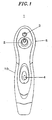
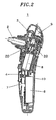
- Fig. 1 is a front view of an appearance of a skin care device 1 and Fig. 2 is a side sectional view showing the internal configuration thereof.
- an approximately lower half of a housing 10 of the skin care device 1 is a grip portion for allowing a user to hold the device 1.
- a suction nozzle 2 is installed at an approximately central portion of the upper half of the housing 10 and a mist nozzle 3 for spraying a mist of a liquid toward skin is provided at a position near and above the suction nozzle 2.
- a main switch 4 for turning on and off the skin care device 1's suctioning operation for suctioning skin impurities is installed at an about central region of a front surface of the housing 10.
- a mist control switch 5 for turning on and off the liquid ejecting operation is provided at an upper right lateral surface of the housing 10.
- a battery 6 such as a rechargeable secondary battery, which serves a power supply of the skin care device 1, a contact terminal 7 of the main switch 4, and so forth.
- a drive motor 8 is installed at an approximately central portion inside the housing 10, and both a suction pump 20 and a liquid supply pump 30 are disposed above the drive motor 8 and behind the suction nozzle 2, when viewed from the front, to face each other with a rotating shaft 81 interposed therebetween.
- a liquid storage tank 9 for storing therein a liquid such as water is disposed above the liquid supply pump 30.
- the skin care device 1 is configured to drive the suction pump 20 and the liquid supply pump 30 simultaneously by using the single drive motor 8.
- the suctioning of skin impurities by the suction nozzle 2 and spraying of liquid by the mist nozzle 3 can be performed at the same time.
- the housing 10 can be reduced in its size with an improved weight balance while making easier to maneuver the skin care device 1.
- the suction pump 20 includes a suction valve 21 for opening or closing a rear end of the suction nozzle 2; an exhaust valve 22 formed as one body with the suction valve 21 to perform on-off operations reverse to those of the suction valve 21; an elastic body (diaphragm) 23 to be deformed to change the volume of the inner space of the suction pump 20; and so forth.
- the suction valve 21 is opened while closing the exhaust valve 22 to thereby take in air from the suction port of the suction nozzle 2.
- the suction valve 21 is closed while opening the exhaust valve 22, so that the air inside the suction pump 20 is discharged from an air outlet.
- the suction valve 21 is opened while closing the exhaust valve 22, so that the inner spaces of the suction nozzle 2 and the suction pump 20 are communicated with each other, while increasing the volume.
- the internal pressures of the suction nozzle 2 and the suction pump 20 are reduced.
- the suction valve 21 is closed, so that the inner space of the suction nozzle 2 is closed as well while maintaining the internal pressure of the suction nozzle 2.
- the exhaust valve 22 is opened, the air inside the suction pump 20 is discharged through the air outlet, so that the internal pressure of the suction pump 20 is made equal to that of the exterior air. If such alternate deformations of the elastic body 23 are repeated, the internal pressure of the suction nozzle 2 is reduced gradually, generating a suction force. As a result, skin impurities can be taken out from the skin.
- the liquid supply pump 30 also includes a suction valve 31 communicating with the outside of the liquid supply pump 30 to suction the exterior air; an exhaust valve 32 formed as one body with the suction valve 31 to perform on-off operations reverse to those of the suction valve 31; an elastic body 33 to be deformed to change the volume of the inner space of the liquid supply pump 30; and so forth.
- An exhaust port 34 of the liquid supply pump 30 is connected to an ejection port of the mist nozzle 3 for ejecting a mist of liquid, to thereby send the air suctioned by the suction valve 31 to the mist nozzle 3 via a connection pipe 40.
- the mist nozzle 3 generates a mist of liquid from the Venturi effect.
- the suction nozzle 2 is configured as an attachment capable of being detachably fitted to the suction pump 20.
- the suction nozzle 2 has a flange 2A formed at an outer periphery of a central portion thereof, and neighboring portions 2B and 2C of the flange 2A have a same outer diameter.
- the suction nozzle 2 can be detachably connected to a mounting portion 27 of the suction pump 20 and, at this time, its front and rear can be reversed.
- the opening of a first suction port at a first end portion 2D of the suction nozzle 2 is designed to have a smaller diameter than that of the opening of a second suction port at a second end portion 2E of the suction nozzle 2.
- the outer diameters of adjacent portions of the first and the second end portion 2D and 2E are set to be smaller than the outer diameters of the neighboring portions 2B and 2C of the flange 2A, respectively.
- a sealing member 28 formed of, e.g., a resilient material such as rubber is installed such that it is firmly attached to the outer peripheral surface of the suction nozzle 2 and the inner peripheral surface of the mounting portion 27 when the suction nozzle 2 is fitted to the mounting portion 27.
- the opening of the first suction port at the first end portion 2D of the suction nozzle 2 is sized so that it ensures tight sealing or cause minimally a gap between the suction port and the skin when it is brought contacts with uneven skins on or around the nostrils or the ridge of the nose.
- the opening of the second suction port at the second end portion 2E of the suction nozzle 2 is sized and shaped so that it allows for an efficient suctioning of skin impurities from the face regions other than the nose, e.g., the cheek.
- the user can remove skin impurities from a desired treatment area of the face efficiently in a short period of time by changing the mounting direction of the suction nozzle 2 appropriately depending on the area of the face to be treated.
- Figs. 4A and 4B provide specific dimensions of the suction nozzle 2.
- Fig. 4A shows the first suction port at the first end portion 2D of the suction nozzle 2 while Fig. 4B shows the second suction port at the second end portion 2E of the suction nozzle 2.
- the opening of the first suction port at the first end portion 2D has, for example, an approximately elliptical shape with a longer diameter of about 4.5 mm and a shorter diameter of about 4.0 mm.
- the thickness of a resin formed along the circumference of the first suction port's opening is about 1.0 mm. Referring to Fig.
- the opening of the second suction port of the second end portion 2E has, for example, an approximately elliptical shape with a longer diameter of about 9.5 mm and a shorter diameter of about 7.0 mm. Further, the thickness of a resin formed along the circumference of the second suction port's opening is about 1.5 mm.
- the material for the suction nozzle 2 is not limited to any specific one, it is preferable to form the suction nozzle 2 with a resilient material such as hard rubber in order to establish a firmer contact between the suction ports of the suction nozzle 2 and the skin.
- the skin care device 1 is configured to remove the user's skin of skin impurities via the suction nozzle 2 while concurrently spraying liquid from the mist nozzle 3 toward the skin.
- the suction nozzle 2 in order to efficiently supply the mist of liquid from the mist nozzle 3 to the vicinities of a face portion in contact with the suction nozzle 2, it is preferable to arrange the suction nozzle 2 such that the openings of the first and the second suction ports are extended in a direction connecting the suction nozzle 2 and the mist nozzle 3, that is, a direction of the longer diameter of the approximately elliptical shapes of the suction ports faces toward the mist nozzle 3.
- the openings of the first and the second suction ports need not be of the approximate elliptical shapes but can have any shapes, e.g., approximately circular shapes. Further, it is apparent that there is no design limitation in the shapes of the openings of the suction ports in case the skin care device does not have the function of spraying a mist.
- a suction nozzle 2 is not provided with a flange but a sealing member 28 is installed at an approximately central area of the outer peripheral portion of the suction nozzle 2 with respect to an axial direction thereof.
- Fig. 5A shows a state where the suction nozzle 2 is coupled to the mounting portion 27 of the suction pump 20 such that a first end portion 2D having a suction port with a smaller-sized opening is oriented outward.
- Fig. 5B shows a state where the suction nozzle 2 is secured to the mounting portion 27 of the suction pump 20 such that a second end portion 2E having a larger suction port is oriented outward.
- Annular protrusions 2F each having an outer diameter identical to the inner diameter of the mounting portion 27 are provided at outer peripheral portions of the suction nozzle 2 in order to prevent the suction nozzle 2 from being inclined when it is attached to the mounting portion 27 of the suction pump 20.
- the protrusions 2F also serve as anti-slipping members for preventing the suction nozzle 2 from slipping when it is connected to or separated from the mounting portion 27.
- the sealing member 28 is installed at the inner peripheral portion of the mounting portion 27 of the suction pump 20, on the other hand, the probability that a user would inadvertently touch the sealing member 28 can be reduced and a damage of the sealing member 28 and a leakage of air due to an attachment error of the sealing member 28 can be prevented though such a configuration has a downside where the outer diameters of the suction nozzle 2 and the suction pump 20 are increased.
- FIG. 6A illustrates a suction nozzle 2 whose outer peripheral surface is of a cylindrical shape while Fig. 6B shows a suction nozzle 2 provided with anti-slipping members 2G at outer peripheral surfaces thereof.
- the suction nozzles 2 in Figs. 6A and 6B tend to be inclined more easily when they are attached to the mounting portion 27 of the suction pump 20, they are advantageous in that they have simpler structures and can be formed by using simple molds with an effect of reducing costs for the fabrication thereof.
- the mounting portion 27 of the suction pump 20 it is also possible to bring the mounting portion 27 of the suction pump 20 into a direct contact with the skin after separating the suction nozzle 2 from the mounting portion 27. In such a case, there is a likelihood that the skin is drawn into the inside of the mounting portion 27, causing hickey marks due to blood congestion because a suction force is determined by a multiplication of the pressure (negative pressure) of the suction pump 20 and the opening area of a suction port.
- the exterior air can be introduced via the elongated hole 29 when the suction nozzle 2 is not coupled, so that the suction force can be appropriately reduced and the problem of the skin being drawn into the inside of the mounting portion 27 can be prevented. As a result, the chance of the user getting hickey marks due to blood congestion can be reduced.
- the suction nozzle 2 is attached to the mounting portion 27 of the suction pump 20, the elongated hole 29 is closed by the outer peripheral portion of the suction nozzle 2, as shown in Fig. 8 , so that skin impurities can be extracted from the skin through the suction ports of the suction nozzle 2 without reducing the suction force.
- the suction force is determined by the multiplication of the pressure of the suction pump 20 and the opening area of a suction port, as described above.
- a sufficient suction force may not be obtained when a suctioning operation is performed by using a first end portion 2D having a suction port with a smaller opening in case the pressure of the suction pump 20 is set to be at a level capable of producing an optimum suction force when the suctioning operation is performed by using a second end portion 2E having a suction port with a larger opening.
- a suction pump 20 is provided with an inner volume control member 50.
- the inner volume control member 50 is slidably supported at a housing 20B of the suction pump 20 such that it can be projected into an inner space 20A of the suction pump 20.
- a suctioning operation is performed by using a second end portion 2E of a suction nozzle 2 where a suction port with a larger opening is located
- a first end portion 2D having a suction port with a smaller opening becomes to contact the housing 20B.
- the inner volume control member 50 is located at the left in the drawing.
- the volume of the inner space of the suction pump 20 is not reduced, thereby making it possible to generate an optimum suction force that can be obtained when the suctioning operation is performed with the second end portion 2E having the larger opening.
- the second end portion 2E having the suction port with the larger opening is forced to contact the inner volume control member 50, making the inner volume control member 50 move into the inner space 20A of the suction pump 20 as shown in Fig. 10 .
- the inner volume of the inner space of the suction pump 20 is reduced, resulting in an increase of the pressure (negative pressure) of the suction pump.
- an optimum suction force can also be obtained in case of performing the suctioning operation through the use of the first end portion 2D having the suction port with the smaller opening.
Landscapes
- Health & Medical Sciences (AREA)
- Heart & Thoracic Surgery (AREA)
- Life Sciences & Earth Sciences (AREA)
- Animal Behavior & Ethology (AREA)
- Engineering & Computer Science (AREA)
- Anesthesiology (AREA)
- Biomedical Technology (AREA)
- Hematology (AREA)
- Veterinary Medicine (AREA)
- Vascular Medicine (AREA)
- General Health & Medical Sciences (AREA)
- Public Health (AREA)
- Pulmonology (AREA)
- Massaging Devices (AREA)
- Finger-Pressure Massage (AREA)
- Devices For Medical Bathing And Washing (AREA)
Claims (8)
- Dispositif pour le soin de la peau (1) comprenant :■ une pompe d'aspiration (20) pour générer une force d'aspiration ;■ un embout d'aspiration (2) fixé de façon amovible à une partie de montage (27) de la pompe d'aspiration (20) et comprenant une première partie d'extrémité (2D) ayant un orifice d'aspiration avec une petite ouverture et une seconde partie d'extrémité (2E) ayant une partie d'aspiration avec une grande ouverture, la première partie d'extrémité (2D) et la seconde partie d'extrémité (2E) pouvant toutes deux être fixées à la partie de montage (27) ;■ un élément d'étanchéité (28) disposé entre une surface périphérique interne de la partie de montage (27) et une surface périphérique externe de l'embout d'aspiration (2), pour sceller un espace entre la partie de montage (27) et l'embout d'aspiration (2) ; et un élément de contrôle de volume interne (50) caractérisé en ce que■ l'élément de contrôle de volume interne (50) est conçu pour modifier le volume d'un espace interne de la pompe d'aspiration (20) selon que la première partie d'extrémité (2D) ou la seconde partie d'extrémité (2E) de l'embout d'aspiration (2) est fixée à la partie de montage (27),dans lequel l'élément de contrôle de volume interne (50) est déplacé par contact sélectif avec les parties d'extrémité (2D ; 2E) de l'embout d'aspiration (2) pour modifier le volume de l'espace interne de la pompe d'aspiration (20).
- Dispositif selon la revendication 1, dans lequel l'élément d'étanchéité (28) est prévu sur une partie périphérique interne de la partie de montage (27).
- Dispositif selon la revendication 1, dans lequel l'élément d'étanchéité (28) est prévu sur une partie périphérique externe de l'embout d'aspiration (2).
- Dispositif selon la revendication 1, dans lequel l'ouverture de chaque orifice d'aspiration a une forme approximativement circulaire ou elliptique.
- Dispositif selon la revendication 1, dans lequel l'embout d'aspiration (2) est formé d'un matériau résilient.
- Dispositif selon la revendication 1, comprenant en outre :■ un embout vaporisateur (3) installé à proximité de l'embout d'aspiration (2), pour pulvériser un brouillard de liquide ;■ un réservoir (9) pour stocker le liquide devant être fourni à l'embout vaporisateur (3) ; et■ une pompe d'alimentation en liquide (30) pour fournir le liquide dans le réservoir (9) à l'embout vaporisateur (3),dans lequel l'ouverture de chaque orifice d'aspiration a une forme approximativement elliptique et l'embout d'aspiration (2) est fixé à la partie de montage (27) de la pompe d'aspiration (20) de telle sorte que la direction d'un diamètre plus long de l'ouverture elliptique de chaque orifice d'aspiration soit orientée vers l'embout pulvérisateur (3).
- Dispositif selon la revendication 1, dans lequel une ouverture (29) est prévue à un ou plusieurs emplacements de la surface périphérique interne de la partie de montage (27).
- Dispositif selon la revendication 1, dans lequel un élément antidérapant (2G) est prévu sur la partie périphérique externe de l'embout d'aspiration (2).
Applications Claiming Priority (2)
| Application Number | Priority Date | Filing Date | Title |
|---|---|---|---|
| JP2004011098A JP2005198988A (ja) | 2004-01-19 | 2004-01-19 | 美顔器 |
| JP2004011098 | 2004-01-19 |
Publications (2)
| Publication Number | Publication Date |
|---|---|
| EP1554948A1 EP1554948A1 (fr) | 2005-07-20 |
| EP1554948B1 true EP1554948B1 (fr) | 2009-01-14 |
Family
ID=34616952
Family Applications (1)
| Application Number | Title | Priority Date | Filing Date |
|---|---|---|---|
| EP05001059A Expired - Lifetime EP1554948B1 (fr) | 2004-01-19 | 2005-01-19 | Dispositif pour le soin de la peau |
Country Status (7)
| Country | Link |
|---|---|
| US (1) | US7396352B2 (fr) |
| EP (1) | EP1554948B1 (fr) |
| JP (1) | JP2005198988A (fr) |
| KR (1) | KR100574142B1 (fr) |
| CN (2) | CN100456992C (fr) |
| AT (1) | ATE420575T1 (fr) |
| DE (1) | DE602005012323D1 (fr) |
Families Citing this family (15)
| Publication number | Priority date | Publication date | Assignee | Title |
|---|---|---|---|---|
| JP3991990B2 (ja) * | 2004-01-19 | 2007-10-17 | 松下電工株式会社 | 美顔器 |
| JP3952021B2 (ja) * | 2004-01-19 | 2007-08-01 | 松下電工株式会社 | 美顔器 |
| FI120786B (fi) | 2008-07-30 | 2010-03-15 | Hld Healthy Life Devices Ltd | Säädettävä hierontalaite ja menetelmä hierontalaitteen säätämiseksi |
| DE202013012252U1 (de) | 2013-09-23 | 2015-11-12 | Novoluto Gmbh | Stimulationsvorrichtung |
| CN103655162A (zh) * | 2013-12-21 | 2014-03-26 | 中山市比森塑料电子制品有限公司 | 一种冷气蒸脸器 |
| US9950147B2 (en) * | 2014-09-12 | 2018-04-24 | Je Matadi, Inc. | Apparatus and method for administering a skin care composition |
| DE202015105689U1 (de) | 2015-03-13 | 2015-11-11 | Novoluto Gmbh | Stimulationsvorrichtung mit Fortsatz |
| DE202016008412U1 (de) | 2016-10-05 | 2017-11-09 | Novoluto Gmbh | Stiftförmige Stimulationsvorrichtung |
| USD847360S1 (en) * | 2017-01-10 | 2019-04-30 | Home Skinovations Ltd. | Skin tightening device |
| DE102018107961A1 (de) | 2018-04-04 | 2019-10-10 | Novoluto Gmbh | Vorrichtung zum Stimulieren der Klitoris mit einem veränderlichen Druckfeld und Verfahren zum Erzeugen eines veränderlichen Druckfelds |
| US11471364B2 (en) | 2019-01-16 | 2022-10-18 | Rodan & Fields, Llc | Skin cleansing device having interchangeable cleansing heads |
| EP3685809B2 (fr) | 2019-01-24 | 2025-10-01 | Novoluto GmbH | Dispositif de stimulation pour un pénis humain |
| USD883470S1 (en) * | 2019-10-23 | 2020-05-05 | Junjie Wei | Nasal aspirator |
| USD1038371S1 (en) * | 2022-10-19 | 2024-08-06 | Shenzhen Dianzhui Culture Technology Co., Ltd. | Ear irrigation device |
| US20230048210A1 (en) * | 2022-11-04 | 2023-02-16 | Dongguan Shuxintang Health Technology Co., Ltd. | Suction toy |
Family Cites Families (14)
| Publication number | Priority date | Publication date | Assignee | Title |
|---|---|---|---|---|
| US2710114A (en) * | 1950-10-17 | 1955-06-07 | Waber Donald | Dispensers for prophylactics |
| JPS534648A (en) | 1976-06-30 | 1978-01-17 | Matsushita Electric Works Ltd | Apparatus for facial treatment |
| US4182329A (en) * | 1977-05-31 | 1980-01-08 | Smit Helen E | Acne facial treatment appliance and method |
| DE3776990D1 (de) * | 1986-07-02 | 1992-04-09 | Sherwood Medical Co | Medizinische sauganordnung. |
| JPH01223903A (ja) * | 1988-03-04 | 1989-09-07 | Jiyanitsukusu Kk | 美容器 |
| JPH0636819Y2 (ja) * | 1988-10-15 | 1994-09-28 | 鐘紡株式会社 | 吸引器 |
| DE4223516C1 (fr) * | 1992-07-17 | 1993-07-22 | Viktor Dipl.-Ing. 5300 Bonn De Schatz | |
| IT230380Y1 (it) * | 1993-07-22 | 1999-06-02 | Daniels Spa | Dispositivo aspirante portatile per uso domestico per il trattamento naturale della cute,in particolare delle rughe |
| JP3324990B2 (ja) | 1998-01-14 | 2002-09-17 | 松下電工株式会社 | 美顔器 |
| JP3290125B2 (ja) | 1998-01-14 | 2002-06-10 | 松下電工株式会社 | 美顔器 |
| TW558982U (en) | 1998-10-26 | 2003-10-21 | Matsushita Electric Works Ltd | Facial aesthetic treatment apparatus |
| JP3870629B2 (ja) * | 1998-10-26 | 2007-01-24 | 松下電工株式会社 | 美顔器 |
| JP2000334009A (ja) | 1999-05-31 | 2000-12-05 | Matsushita Electric Works Ltd | 美顔器 |
| JP3864652B2 (ja) | 1999-12-10 | 2007-01-10 | 松下電工株式会社 | 美顔器 |
-
2004
- 2004-01-19 JP JP2004011098A patent/JP2005198988A/ja active Pending
-
2005
- 2005-01-18 KR KR1020050004535A patent/KR100574142B1/ko not_active Expired - Fee Related
- 2005-01-19 EP EP05001059A patent/EP1554948B1/fr not_active Expired - Lifetime
- 2005-01-19 CN CNB2005100542627A patent/CN100456992C/zh not_active Expired - Fee Related
- 2005-01-19 CN CNU200520004160XU patent/CN2796696Y/zh not_active Expired - Fee Related
- 2005-01-19 AT AT05001059T patent/ATE420575T1/de not_active IP Right Cessation
- 2005-01-19 DE DE602005012323T patent/DE602005012323D1/de not_active Expired - Lifetime
- 2005-01-19 US US11/037,254 patent/US7396352B2/en not_active Expired - Fee Related
Also Published As
| Publication number | Publication date |
|---|---|
| JP2005198988A (ja) | 2005-07-28 |
| US7396352B2 (en) | 2008-07-08 |
| CN2796696Y (zh) | 2006-07-19 |
| US20050159684A1 (en) | 2005-07-21 |
| KR20050076644A (ko) | 2005-07-26 |
| CN100456992C (zh) | 2009-02-04 |
| DE602005012323D1 (de) | 2009-03-05 |
| ATE420575T1 (de) | 2009-01-15 |
| EP1554948A1 (fr) | 2005-07-20 |
| KR100574142B1 (ko) | 2006-04-26 |
| HK1078763A1 (zh) | 2006-03-24 |
| CN1657033A (zh) | 2005-08-24 |
Similar Documents
| Publication | Publication Date | Title |
|---|---|---|
| EP1554948B1 (fr) | Dispositif pour le soin de la peau | |
| EP0365230B1 (fr) | Dispositif d'aspiration | |
| US7431718B2 (en) | Skin care device for taking out and removing sebum or other cutaneous impurities | |
| US6517511B2 (en) | Cleansable multi-purpose nasal discharge aspirator | |
| JP3991990B2 (ja) | 美顔器 | |
| US6938838B2 (en) | Nozzle and aspirator with nozzle | |
| WO2018224026A1 (fr) | Aspirateur | |
| JP2020124043A (ja) | ケアユニット | |
| JP2003169828A (ja) | 使い捨て痩身用吸引カップ | |
| HK1078763B (en) | Skin care device | |
| JP4775028B2 (ja) | 美顔器 | |
| US20050023377A1 (en) | Nozzle and aspirator with nozzle | |
| CN218551667U (zh) | 具有喷水功能的清洁刷 | |
| CN222149886U (zh) | 自动面部深度清洗装置 | |
| CN223773634U (zh) | 一种便携式电动清洗器 | |
| CN223846022U (zh) | 一种吸鼻器 | |
| JPS5826042Y2 (ja) | 電動噴霧器 | |
| KR200297391Y1 (ko) | 귀이개 | |
| JPH09289956A (ja) | 鼻又は耳掃除器 | |
| TWI602558B (zh) | Hand-held help defecation device | |
| CN111558101A (zh) | 洁阴器 | |
| JPS601699Y2 (ja) | 美顔器の吸引アタツチメント | |
| JP2003125986A (ja) | 掃除機用アタチメント、及び掃除機 | |
| KR20200002199U (ko) | 피지 제거기 | |
| JP2003325435A (ja) | 内視鏡の先端部 |
Legal Events
| Date | Code | Title | Description |
|---|---|---|---|
| PUAI | Public reference made under article 153(3) epc to a published international application that has entered the european phase |
Free format text: ORIGINAL CODE: 0009012 |
|
| AK | Designated contracting states |
Kind code of ref document: A1 Designated state(s): AT BE BG CH CY CZ DE DK EE ES FI FR GB GR HU IE IS IT LI LT LU MC NL PL PT RO SE SI SK TR |
|
| AX | Request for extension of the european patent |
Extension state: AL BA HR LV MK YU |
|
| 17P | Request for examination filed |
Effective date: 20060117 |
|
| AKX | Designation fees paid |
Designated state(s): AT BE BG CH CY CZ DE DK EE ES FI FR GB GR HU IE IS IT LI LT LU MC NL PL PT RO SE SI SK TR |
|
| 17Q | First examination report despatched |
Effective date: 20071005 |
|
| GRAP | Despatch of communication of intention to grant a patent |
Free format text: ORIGINAL CODE: EPIDOSNIGR1 |
|
| GRAS | Grant fee paid |
Free format text: ORIGINAL CODE: EPIDOSNIGR3 |
|
| GRAA | (expected) grant |
Free format text: ORIGINAL CODE: 0009210 |
|
| AK | Designated contracting states |
Kind code of ref document: B1 Designated state(s): AT BE BG CH CY CZ DE DK EE ES FI FR GB GR HU IE IS IT LI LT LU MC NL PL PT RO SE SI SK TR |
|
| REG | Reference to a national code |
Ref country code: GB Ref legal event code: FG4D |
|
| REG | Reference to a national code |
Ref country code: CH Ref legal event code: EP |
|
| RAP2 | Party data changed (patent owner data changed or rights of a patent transferred) |
Owner name: PANASONIC ELECTRIC WORKS CO., LTD. |
|
| REG | Reference to a national code |
Ref country code: IE Ref legal event code: FG4D |
|
| REF | Corresponds to: |
Ref document number: 602005012323 Country of ref document: DE Date of ref document: 20090305 Kind code of ref document: P |
|
| NLT2 | Nl: modifications (of names), taken from the european patent patent bulletin |
Owner name: PANASONIC ELECTRIC WORKS CO., LTD. Effective date: 20090218 |
|
| PG25 | Lapsed in a contracting state [announced via postgrant information from national office to epo] |
Ref country code: NL Free format text: LAPSE BECAUSE OF FAILURE TO SUBMIT A TRANSLATION OF THE DESCRIPTION OR TO PAY THE FEE WITHIN THE PRESCRIBED TIME-LIMIT Effective date: 20090114 |
|
| NLV1 | Nl: lapsed or annulled due to failure to fulfill the requirements of art. 29p and 29m of the patents act | ||
| PG25 | Lapsed in a contracting state [announced via postgrant information from national office to epo] |
Ref country code: LT Free format text: LAPSE BECAUSE OF FAILURE TO SUBMIT A TRANSLATION OF THE DESCRIPTION OR TO PAY THE FEE WITHIN THE PRESCRIBED TIME-LIMIT Effective date: 20090114 Ref country code: ES Free format text: LAPSE BECAUSE OF FAILURE TO SUBMIT A TRANSLATION OF THE DESCRIPTION OR TO PAY THE FEE WITHIN THE PRESCRIBED TIME-LIMIT Effective date: 20090425 Ref country code: FI Free format text: LAPSE BECAUSE OF FAILURE TO SUBMIT A TRANSLATION OF THE DESCRIPTION OR TO PAY THE FEE WITHIN THE PRESCRIBED TIME-LIMIT Effective date: 20090114 Ref country code: SI Free format text: LAPSE BECAUSE OF FAILURE TO SUBMIT A TRANSLATION OF THE DESCRIPTION OR TO PAY THE FEE WITHIN THE PRESCRIBED TIME-LIMIT Effective date: 20090114 |
|
| PG25 | Lapsed in a contracting state [announced via postgrant information from national office to epo] |
Ref country code: MC Free format text: LAPSE BECAUSE OF NON-PAYMENT OF DUE FEES Effective date: 20090131 Ref country code: PT Free format text: LAPSE BECAUSE OF FAILURE TO SUBMIT A TRANSLATION OF THE DESCRIPTION OR TO PAY THE FEE WITHIN THE PRESCRIBED TIME-LIMIT Effective date: 20090615 Ref country code: SE Free format text: LAPSE BECAUSE OF FAILURE TO SUBMIT A TRANSLATION OF THE DESCRIPTION OR TO PAY THE FEE WITHIN THE PRESCRIBED TIME-LIMIT Effective date: 20090414 Ref country code: PL Free format text: LAPSE BECAUSE OF FAILURE TO SUBMIT A TRANSLATION OF THE DESCRIPTION OR TO PAY THE FEE WITHIN THE PRESCRIBED TIME-LIMIT Effective date: 20090114 Ref country code: IS Free format text: LAPSE BECAUSE OF FAILURE TO SUBMIT A TRANSLATION OF THE DESCRIPTION OR TO PAY THE FEE WITHIN THE PRESCRIBED TIME-LIMIT Effective date: 20090514 Ref country code: AT Free format text: LAPSE BECAUSE OF FAILURE TO SUBMIT A TRANSLATION OF THE DESCRIPTION OR TO PAY THE FEE WITHIN THE PRESCRIBED TIME-LIMIT Effective date: 20090114 |
|
| REG | Reference to a national code |
Ref country code: CH Ref legal event code: PL |
|
| PG25 | Lapsed in a contracting state [announced via postgrant information from national office to epo] |
Ref country code: BE Free format text: LAPSE BECAUSE OF FAILURE TO SUBMIT A TRANSLATION OF THE DESCRIPTION OR TO PAY THE FEE WITHIN THE PRESCRIBED TIME-LIMIT Effective date: 20090114 |
|
| REG | Reference to a national code |
Ref country code: IE Ref legal event code: MM4A |
|
| PG25 | Lapsed in a contracting state [announced via postgrant information from national office to epo] |
Ref country code: CZ Free format text: LAPSE BECAUSE OF FAILURE TO SUBMIT A TRANSLATION OF THE DESCRIPTION OR TO PAY THE FEE WITHIN THE PRESCRIBED TIME-LIMIT Effective date: 20090114 Ref country code: DK Free format text: LAPSE BECAUSE OF FAILURE TO SUBMIT A TRANSLATION OF THE DESCRIPTION OR TO PAY THE FEE WITHIN THE PRESCRIBED TIME-LIMIT Effective date: 20090114 Ref country code: EE Free format text: LAPSE BECAUSE OF FAILURE TO SUBMIT A TRANSLATION OF THE DESCRIPTION OR TO PAY THE FEE WITHIN THE PRESCRIBED TIME-LIMIT Effective date: 20090114 Ref country code: LI Free format text: LAPSE BECAUSE OF NON-PAYMENT OF DUE FEES Effective date: 20090131 Ref country code: CH Free format text: LAPSE BECAUSE OF NON-PAYMENT OF DUE FEES Effective date: 20090131 |
|
| PLBE | No opposition filed within time limit |
Free format text: ORIGINAL CODE: 0009261 |
|
| STAA | Information on the status of an ep patent application or granted ep patent |
Free format text: STATUS: NO OPPOSITION FILED WITHIN TIME LIMIT |
|
| REG | Reference to a national code |
Ref country code: FR Ref legal event code: ST Effective date: 20091030 |
|
| PG25 | Lapsed in a contracting state [announced via postgrant information from national office to epo] |
Ref country code: SK Free format text: LAPSE BECAUSE OF FAILURE TO SUBMIT A TRANSLATION OF THE DESCRIPTION OR TO PAY THE FEE WITHIN THE PRESCRIBED TIME-LIMIT Effective date: 20090114 Ref country code: RO Free format text: LAPSE BECAUSE OF FAILURE TO SUBMIT A TRANSLATION OF THE DESCRIPTION OR TO PAY THE FEE WITHIN THE PRESCRIBED TIME-LIMIT Effective date: 20090114 |
|
| 26N | No opposition filed |
Effective date: 20091015 |
|
| GBPC | Gb: european patent ceased through non-payment of renewal fee |
Effective date: 20090414 |
|
| PG25 | Lapsed in a contracting state [announced via postgrant information from national office to epo] |
Ref country code: BG Free format text: LAPSE BECAUSE OF FAILURE TO SUBMIT A TRANSLATION OF THE DESCRIPTION OR TO PAY THE FEE WITHIN THE PRESCRIBED TIME-LIMIT Effective date: 20090414 Ref country code: IE Free format text: LAPSE BECAUSE OF NON-PAYMENT OF DUE FEES Effective date: 20090119 |
|
| PG25 | Lapsed in a contracting state [announced via postgrant information from national office to epo] |
Ref country code: GB Free format text: LAPSE BECAUSE OF NON-PAYMENT OF DUE FEES Effective date: 20090414 Ref country code: FR Free format text: LAPSE BECAUSE OF NON-PAYMENT OF DUE FEES Effective date: 20090316 |
|
| PG25 | Lapsed in a contracting state [announced via postgrant information from national office to epo] |
Ref country code: GR Free format text: LAPSE BECAUSE OF FAILURE TO SUBMIT A TRANSLATION OF THE DESCRIPTION OR TO PAY THE FEE WITHIN THE PRESCRIBED TIME-LIMIT Effective date: 20090415 |
|
| PG25 | Lapsed in a contracting state [announced via postgrant information from national office to epo] |
Ref country code: IT Free format text: LAPSE BECAUSE OF FAILURE TO SUBMIT A TRANSLATION OF THE DESCRIPTION OR TO PAY THE FEE WITHIN THE PRESCRIBED TIME-LIMIT Effective date: 20090114 |
|
| PG25 | Lapsed in a contracting state [announced via postgrant information from national office to epo] |
Ref country code: LU Free format text: LAPSE BECAUSE OF NON-PAYMENT OF DUE FEES Effective date: 20090119 |
|
| PG25 | Lapsed in a contracting state [announced via postgrant information from national office to epo] |
Ref country code: HU Free format text: LAPSE BECAUSE OF FAILURE TO SUBMIT A TRANSLATION OF THE DESCRIPTION OR TO PAY THE FEE WITHIN THE PRESCRIBED TIME-LIMIT Effective date: 20090715 |
|
| PG25 | Lapsed in a contracting state [announced via postgrant information from national office to epo] |
Ref country code: TR Free format text: LAPSE BECAUSE OF FAILURE TO SUBMIT A TRANSLATION OF THE DESCRIPTION OR TO PAY THE FEE WITHIN THE PRESCRIBED TIME-LIMIT Effective date: 20090114 |
|
| PG25 | Lapsed in a contracting state [announced via postgrant information from national office to epo] |
Ref country code: CY Free format text: LAPSE BECAUSE OF FAILURE TO SUBMIT A TRANSLATION OF THE DESCRIPTION OR TO PAY THE FEE WITHIN THE PRESCRIBED TIME-LIMIT Effective date: 20090114 |
|
| REG | Reference to a national code |
Ref country code: DE Ref legal event code: R084 Ref document number: 602005012323 Country of ref document: DE Effective date: 20111122 |
|
| PGFP | Annual fee paid to national office [announced via postgrant information from national office to epo] |
Ref country code: DE Payment date: 20140115 Year of fee payment: 10 |
|
| REG | Reference to a national code |
Ref country code: DE Ref legal event code: R119 Ref document number: 602005012323 Country of ref document: DE |
|
| PG25 | Lapsed in a contracting state [announced via postgrant information from national office to epo] |
Ref country code: DE Free format text: LAPSE BECAUSE OF NON-PAYMENT OF DUE FEES Effective date: 20150801 |