EP1555050B1 - Verbesserung einer Haltegurtbefestigung oder dergleichen für einen Schuh an einem Sportgerät - Google Patents
Verbesserung einer Haltegurtbefestigung oder dergleichen für einen Schuh an einem Sportgerät Download PDFInfo
- Publication number
- EP1555050B1 EP1555050B1 EP05290097A EP05290097A EP1555050B1 EP 1555050 B1 EP1555050 B1 EP 1555050B1 EP 05290097 A EP05290097 A EP 05290097A EP 05290097 A EP05290097 A EP 05290097A EP 1555050 B1 EP1555050 B1 EP 1555050B1
- Authority
- EP
- European Patent Office
- Prior art keywords
- strap
- length
- main
- adjustment
- shoe
- Prior art date
- Legal status (The legal status is an assumption and is not a legal conclusion. Google has not performed a legal analysis and makes no representation as to the accuracy of the status listed.)
- Expired - Lifetime
Links
Images
Classifications
-
- A—HUMAN NECESSITIES
- A63—SPORTS; GAMES; AMUSEMENTS
- A63C—SKATES; SKIS; ROLLER SKATES; DESIGN OR LAYOUT OF COURTS, RINKS OR THE LIKE
- A63C13/00—Snow shoes
- A63C13/001—Bindings therefor
-
- A—HUMAN NECESSITIES
- A63—SPORTS; GAMES; AMUSEMENTS
- A63C—SKATES; SKIS; ROLLER SKATES; DESIGN OR LAYOUT OF COURTS, RINKS OR THE LIKE
- A63C9/00—Ski bindings
- A63C9/002—Strap closures or latches; Leashes
Definitions
- the present invention relates to a device for retaining a boot on a sports article and more particularly relates to an improvement of a strap retaining device, or the like.
- the invention is more specifically intended to hold a shoe on a pivoting plate for retaining a shoe on a snowshoe, but it can be used for any type of sports article, without departing from the scope of the invention , such as for fixing for the practice of surfing, skiing, or other.
- Snowshoes have been known for many years because they have been used for centuries by Scandinavians to move on snow. Until today, snowshoes were used for utilitarian or military purposes, to allow alpine populations and troops to move on the snow in their movements necessitated by daily life. Currently, snowshoes are mostly used by walkers or athletes who go hiking and walking, or even competitions.
- the shoe retaining devices of the users on known snowshoes most often comprise front retaining means and rear retaining means arranged on a hinged plate on the sieve. These devices of the prior art generally have a good hold of the front end of the shoe on the plate, but however have drawbacks in the holding of the rear end of the shoe. Indeed, if the means of restraint before snowshoes are generally provided to be able to adapt to any type of shoe while ensuring a good hold of the front of the foot, rear retaining means, they do not have such characteristics.
- rear retaining means for example, for being arranged on hinged plates such as sliding or fixed heels, said heels being intended to hold the heel of the user against the plate at the end. using a belt or a strap tightening the foot of the user back against a stop wall of the heel.
- the present invention proposes to improve the rear retaining strap which is intended to pass on the kick.
- Current straps are constituted by a textile strap comprising a length adjustment loop to adapt to the size of the user's shoe and provide effective tightening without play, including the kick.
- Textile straps are now often replaced by a rigid or semi-rigid strap made of a plastic material.
- These straps are constituted by two portions interconnected by locking means of the type such as for example a ratchet device for cooperating incrementally with a succession of teeth made on the other portion of the strap.
- locking means make it possible to adapt the length of the strap to the volume of the boot, and in particular the kick perimeter, but also to ensure correct tightening to have a satisfactory restraint of the boot.
- these straps do not allow to adapt to larger and at the smallest sizes and usually include presets with screws, which requires tooling and takes time.
- the document FR 2 820 049 discloses a device of this type.
- the present invention wants to solve the disadvantages of traditional systems by means of simple, reliable, inexpensive and easy to implement in order to obtain a satisfactory performance of the shoe, a quick preset, and a simple implementation and convenient.
- the kick strap comprises first means or means for presetting the length of the strap and second means or means for final adjustment of the length of the strap, tightening and locking ensuring the final adjustment the length of the strap.
- the first means or presetting means are independent of the second means or final adjustment means
- the secondary strap comprises in combination with the main strap to which it is connected the first adjustment means or presetting means of the length of the strap, said connection being constituted by an adjustable connection formed by an adjustment loop while said secondary strap is connected by its free end to the retaining piece, and that its other end is engaged in the adjustment loop, the latter being integral or constituting the end of the first portion of the main strap.
- the secondary strap is a soft textile strap.
- the device for retaining a boot on a sports article such as a snowshoe is constituted by a retaining strap, and is characterized in that the strap comprises first means or means for presetting the length of the strap and second means or means of final adjustment of the strap length, tightening and locking ensuring the final adjustment of the length of the strap, the latter being independent of the presetting means, while the strap of coup foot is constituted by a main strap and a secondary strap.
- the main strap comprises the second means or means for final adjustment of the length of the tightening and locking strap ensuring the final adjustment of the length of the strap, while it consists of two portions of strap connected between them by locking means of type comprising for example pivoting ratchet pivotally mounted on one of the strap portions, for incrementally cooperating with a succession of retaining teeth made on the other strap portion.
- the main strap is made of semi-rigid material such as plastic, and the first portion of the main strap is connected to the secondary strap, while the other portion or second portion of the main strap is connected to the rear retaining piece.
- the device of the invention allows to have a precise adjustment and allows a release of the shoe greatly favored, which in case of blockage of the final adjustment system for example in case of frost or accumulation of Snow is an undeniable advantage.
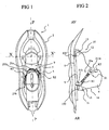
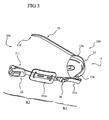
- FIGS. 1 and 2 are respectively views, on the one hand, from above of the snowshoe equipped with the retaining device according to the invention, for the figure 1 , and secondly, lateral for the figure 2 of the same racket, the figure 1 being represented without the shoe for better understanding.
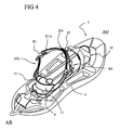
- the figure 3 is a perspective view illustrating the invention better.
- the figure 4 is a perspective view, showing the racket with its pivoting plate equipped with the shoe retaining device according to the invention.
- the racket designated under the general reference (1) is in the form of a perforated plate of general plane of symmetry (P), fixed under the shoe and which consists of a main frame (2) and a sieve (4) comprising a set of walls supporting the retaining device (5) of the shoe (6) of the user, as shown by the Figures 1 and 2 .
- P general plane of symmetry
- Said sieve (4) with its set of internal walls forms a general lower surface of support on the snow allowing the user not to sink too much into the snow, and this, thanks to the relatively large bearing surface.
- the retaining device (5) of the shoe (6) is, according to the illustration given by way of example, articulated with respect to the sieve (4) of the racquet itself, along a transverse axis (XX ') .
- the retainer bearing the general reference (5) is advantageously constituted by an articulated plate (9) comprising retaining means for the boot, namely, front retaining means (10) and rear retaining means ( 11).
- the front end (12) of the shoe retained by the front holding means (10) is, for example, constituted by a front stirrup (13), while its rear end (14) is constituted by one of the rear retaining means (11) comprising a rear retaining piece (15).
- the rear retaining means (11) comprise a clamping device intended to allow clamping and thus fixing, and the lateral and vertical retention of the rear end (14) of the shoe (6) against or within a forwardly open housing formed by a set of walls of the rear retaining piece (15).
- the invention is not limited to a system in which the front of the boot is retained by a stirrup, because the invention can be applied to a fixation of a completely different kind.
- the rear retaining piece (15) is slidably mounted and adjustable in position on the plate (9) and comprises a bead wall (150) of heel, and it is against this wall that is retained the heel of the shoes thanks to the device of the invention.
- a strap (21) known as a kick strap The latter forms a loop whose ends are fixed to the rear retaining piece (15) and more particularly to its interlocking wall and more specifically to its side walls (15a, 15b), as visible on the figure 3 .
- the retaining strap (21) comprises first means or means for presetting the length of the strap (R1), and second means or means for final adjustment of the length of strap, tightening and locking ensuring the final adjustment of the length of the strap (R2), the latter being independent of the presetting means.
- the kick strap (21) is constituted by a main strap (21a) and a secondary strap (21b).
- the main strap (21a) comprises the second means (R2) or means for final adjustment of the length of the tightening and locking strap ensuring the final adjustment of the length of the strap.
- This main strap (21a) is constituted by two strap portions (210, 211) interconnected by locking means of the type comprising for example pivoting ratchet (22) pivotally mounted on one of the strap portions (211, or 210), for incrementally cooperating with a succession of retaining teeth (23) made on the other strap portion (210, or 211).
- locking means make it possible to adapt the length of the strap to the volume of the boot, in order to ensure correct tightening to have a satisfactory restraint of the boot.
- the main strap (21a) is made of semi-rigid material such as plastic.
- the first main strap portion (211) is connected to the secondary strap (21b), while the other portion (210) or second main strap portion is connected to the rear retainer (15).
- the secondary strap (21b) comprises in combination with the main strap to which it is connected the first adjustment means (R1), or means of presetting the length of the strap.
- connection of the secondary strap (21b) with for example the first portion of main strap (211) is constituted by an adjustable connection formed by an adjustment loop (24).
- this secondary strap (21b) is connected by its free end to the retaining piece (15), and more particularly to its interlocking wall (150), while its other end is engaged in the adjustment loop (24), the latter being integral or constituting the end of the first portion (211) of the main strap.
- the user will operate a preset length by the first adjustment means or presetting means (R1), to adapt the attachment to the size of the shoe and center the main strap (21a) on the kick, and during each boot it will only have to use the second means or means of final adjustment (R2) of the length of the tightening and locking strap to ensure the final adjustment of the length of the strap, allowing the restraint of the shoe.
- the main strap may advantageously comprise a comfort piece (211a) for the kick, as schematically illustrated in dotted lines on the figure 3 , and in this case it is understood that the first adjustment means (R1), allow to center said comfort piece on the kick, thus ensuring better comfort and better footing.
- the secondary strap (21b) is made by a flexible textile strap.
- the strap of the invention can of course be used to hold a shoe on a gliding board such as a ski or a surf, see a water ski and the like.
Landscapes
- Footwear And Its Accessory, Manufacturing Method And Apparatuses (AREA)
Claims (4)
- Vorrichtung (5) zur Halterung eines Schuhs (6) auf einem Sportartikel, wie beispielsweise einem Schneeschuh (1), der mit einem Befestigungsriemen (21) ausgebildet ist, wobei der Schneeschuh erste Mittel (R1) oder Mittel zum Voreinstellen der Länge des Riemens, und zweite Mittel (R2) oder Mittel zum endgültigen Einstellen der Länge des Riemens, zum Festklemmen und zum Sichern der endgültigen Einstellung der Länge des Riemens aufweist, wobei die letzteren unabhängig von den Mitteln zum Voreinstellen ausgebildet sind, und der Befestigungsriemen (21) aus einem Primärriemen (21a) und einem Sekundärriemen (21b) gebildet ist, der erste Abschnitt (211) des Hauptriemens am Sekundärriemen (21b) befestigt ist, während ein anderer (210) Abschnitt oder zweiter Abschnitt des Primärriemens an einer hinteren Halterung (15) befestigt ist, der Sekundärriemen (21 b) in Kombination mit dem Primärriemen, mit welchem er verbunden ist, die ersten Mittel oder Mittel zur Voreinstellung der Länge des Riemens aufweist, wobei die Verbindung aus einer einstellbaren Verbindung gebildet ist, die von einer Einstellschnalle (24) gebildet ist, während der Sekundärriemen an seinem freien Ende an der hinteren Halterung (15) befestigt ist, und sich sein anderes Ende mit der Einstellschnalle (24) in Eingriff befindet, wobei letztere einstückig ausgebildet ist oder das Ende des ersten Abschnitts (211) des Primärriemens bildet, dadurch gekennzeichnet, dass der Sekundärriemen (21b) ein Riemen aus weichem Textilmaterial ist.
- Vorrichtung nach Anspruch (1), dadurch gekennzeichnet, dass der Primärriemen (21a) die zweiten Mittel oder Mittel zum endgültigen Einstellen der Länge des Riemens, zum Festklemmen und zum Sichern der endgültigen Einstellung der Länge des Riemens, aufweist.
- Vorrichtung nach Anspruch (2), dadurch gekennzeichnet, dass der Primärriemen (21a) aus zwei Riemenabschnitten (210, 211) gebildet ist, die untereinander mittels Sicherungsmitteln, beispielweise des Typs mit einer aufklappbaren Rasteinrichtung (22), verbunden sind, die auf einem der Riemenabschnitte (211, oder 210) aufklappbar angeordnet ist und zum Zusammenwirken durch Inkrementierung mit einer Aufeinanderfolge von auf dem anderen Riemenabschnitt (210, oder 211) angeordneten Haltezähnen (23) ausgebildet ist.
- Vorrichtung nach einem der vorstehenden Ansprüche, dadurch gekennzeichnet, dass der Primärriemen (21a) aus einem halbstarren Material, wie beispielsweise aus Kunststoff aufgebildet ist.
Applications Claiming Priority (2)
| Application Number | Priority Date | Filing Date | Title |
|---|---|---|---|
| FR0400514 | 2004-01-16 | ||
| FR0400514 | 2004-01-16 |
Publications (3)
| Publication Number | Publication Date |
|---|---|
| EP1555050A2 EP1555050A2 (de) | 2005-07-20 |
| EP1555050A3 EP1555050A3 (de) | 2006-03-15 |
| EP1555050B1 true EP1555050B1 (de) | 2011-11-16 |
Family
ID=34610788
Family Applications (1)
| Application Number | Title | Priority Date | Filing Date |
|---|---|---|---|
| EP05290097A Expired - Lifetime EP1555050B1 (de) | 2004-01-16 | 2005-01-14 | Verbesserung einer Haltegurtbefestigung oder dergleichen für einen Schuh an einem Sportgerät |
Country Status (2)
| Country | Link |
|---|---|
| EP (1) | EP1555050B1 (de) |
| AT (1) | ATE533539T1 (de) |
Families Citing this family (5)
| Publication number | Priority date | Publication date | Assignee | Title |
|---|---|---|---|---|
| US7681904B2 (en) | 2002-08-02 | 2010-03-23 | Lane Ekberg | Configurable snowshoe and ski device |
| US8348299B2 (en) | 2005-10-07 | 2013-01-08 | Lane Ekberg | Multiple direct lock positions for touring ski mounting plate |
| US9079094B2 (en) | 2005-10-07 | 2015-07-14 | Lane A. Ekberg | Multiple direct touring positions for snowboard boot binding mounting base |
| FR2907345B1 (fr) * | 2006-10-20 | 2009-01-16 | Tsl Sport Equipment Sa | Dispositif de retenue par sangle d'une chaussure sur un article de sport |
| FR2941381B1 (fr) * | 2009-01-28 | 2011-02-25 | Tsl Soprt Equipement | Dispositif de retenue par sangle d'une chaussure sur un article de sport |
Family Cites Families (2)
| Publication number | Priority date | Publication date | Assignee | Title |
|---|---|---|---|---|
| FR2755028B1 (fr) * | 1996-10-31 | 1999-01-15 | Salomon Sa | Dispositif de liaison par sangle d'une chaussure |
| FR2820049B1 (fr) * | 2001-01-31 | 2003-03-21 | Salomon Sa | Dispositif de retenue d'une chaussure sur un engin de sport |
-
2005
- 2005-01-14 AT AT05290097T patent/ATE533539T1/de active
- 2005-01-14 EP EP05290097A patent/EP1555050B1/de not_active Expired - Lifetime
Also Published As
| Publication number | Publication date |
|---|---|
| EP1555050A3 (de) | 2006-03-15 |
| ATE533539T1 (de) | 2011-12-15 |
| EP1555050A2 (de) | 2005-07-20 |
Similar Documents
| Publication | Publication Date | Title |
|---|---|---|
| EP1837059B1 (de) | Perfektionierung für Bindung zum Befestigen von Schuhen auf Schneeschuhen | |
| EP1162898B1 (de) | Schuh mit einer kippgestängelasche zur versteifung von der vorderseite des schuhs, insbesondere eines snowboardstiefels | |
| EP0839557B1 (de) | Gurtverbindungsvorrichtung für einen Schuh | |
| FR2749738A1 (fr) | Dispositif de serrage par sangle dentee et organe de verrouillage a cliquet | |
| FR2744032A1 (fr) | Dispositif de retenue d'une chaussure sur une raquette a neige | |
| EP1555050A2 (de) | Verbesserung einer Haltegurtbefestigung oder dergleichen für einen Schuh an einem Sportgerät | |
| EP1327467A1 (de) | Vorrichtung zum Befestigen eines Schuhs auf einem Sportgerät | |
| EP3491955B1 (de) | Spannvorrichtung für sportschuh | |
| EP2213342B1 (de) | Gurthaltevorrichtung für einen Schuh auf einem Sportgerät | |
| FR2719783A1 (fr) | Perfectionnement pour le dispositif de retenue d'une chaussure sur une raquette à neige. | |
| EP1530987B1 (de) | Snowboardbindung | |
| CA2575333A1 (fr) | Dispositif retenue d'une chaussure sur une raquette a neige | |
| EP1913984A1 (de) | Perfektionierung für Gurthaltevorrichtung für einen Schuh auf einem Sportgerät | |
| FR2717093A1 (fr) | Perfectionnement pour raquette à neige. | |
| FR2820333A1 (fr) | Systeme de fixation pour un engin de sport et engin de sport comportant un tel systeme | |
| EP3157643A1 (de) | Befestigung für einen stiefel auf einem schneeschuh | |
| EP3199214A1 (de) | Mehrzweck-rückhaltevorrichtung für ski mit auskuppelbarer befestigung, und für einen solchen ski angepasster skischuh | |
| EP2085122B1 (de) | Schwimmflosse | |
| FR2769800A1 (fr) | Chaussure de ski ou de patin a roulettes en ligne | |
| FR2878757A1 (fr) | Dispositif de maintien d'un pied ou d'une chaussure sur un engin de sport | |
| FR2903914A1 (fr) | Dispositif de reception d'une chaussure ou similaire sur une raquette a neige et raquette a neige equipee d'un tel dispositif de reception. | |
| FR2825287A1 (fr) | Ensemble de retenue d'une chaussure sur un engin de sport | |
| FR2770144A1 (fr) | Perfectionnement pour fixation a sangle | |
| FR2819196A3 (fr) | Element de serrage, en particulier pour des fixations pour des chaussures de sport | |
| EP0736312A1 (de) | Vervollkommung des Aufbaus eines Schneeschuhs |
Legal Events
| Date | Code | Title | Description |
|---|---|---|---|
| PUAI | Public reference made under article 153(3) epc to a published international application that has entered the european phase |
Free format text: ORIGINAL CODE: 0009012 |
|
| AK | Designated contracting states |
Kind code of ref document: A2 Designated state(s): AT BE BG CH CY CZ DE DK EE ES FI FR GB GR HU IE IS IT LI LT LU MC NL PL PT RO SE SI SK TR |
|
| AX | Request for extension of the european patent |
Extension state: AL BA HR LV MK YU |
|
| PUAL | Search report despatched |
Free format text: ORIGINAL CODE: 0009013 |
|
| AK | Designated contracting states |
Kind code of ref document: A3 Designated state(s): AT BE BG CH CY CZ DE DK EE ES FI FR GB GR HU IE IS IT LI LT LU MC NL PL PT RO SE SI SK TR |
|
| AX | Request for extension of the european patent |
Extension state: AL BA HR LV MK YU |
|
| 17P | Request for examination filed |
Effective date: 20060411 |
|
| AKX | Designation fees paid |
Designated state(s): AT CH DE FR IT LI |
|
| 17Q | First examination report despatched |
Effective date: 20090707 |
|
| GRAP | Despatch of communication of intention to grant a patent |
Free format text: ORIGINAL CODE: EPIDOSNIGR1 |
|
| GRAS | Grant fee paid |
Free format text: ORIGINAL CODE: EPIDOSNIGR3 |
|
| GRAA | (expected) grant |
Free format text: ORIGINAL CODE: 0009210 |
|
| AK | Designated contracting states |
Kind code of ref document: B1 Designated state(s): AT CH DE FR IT LI |
|
| REG | Reference to a national code |
Ref country code: CH Ref legal event code: EP |
|
| REG | Reference to a national code |
Ref country code: DE Ref legal event code: R096 Ref document number: 602005031202 Country of ref document: DE Effective date: 20120112 |
|
| REG | Reference to a national code |
Ref country code: CH Ref legal event code: NV Representative=s name: AMMANN PATENTANWAELTE AG BERN |
|
| PG25 | Lapsed in a contracting state [announced via postgrant information from national office to epo] |
Ref country code: IT Free format text: LAPSE BECAUSE OF FAILURE TO SUBMIT A TRANSLATION OF THE DESCRIPTION OR TO PAY THE FEE WITHIN THE PRESCRIBED TIME-LIMIT Effective date: 20111116 |
|
| REG | Reference to a national code |
Ref country code: AT Ref legal event code: MK05 Ref document number: 533539 Country of ref document: AT Kind code of ref document: T Effective date: 20111116 |
|
| PLBE | No opposition filed within time limit |
Free format text: ORIGINAL CODE: 0009261 |
|
| STAA | Information on the status of an ep patent application or granted ep patent |
Free format text: STATUS: NO OPPOSITION FILED WITHIN TIME LIMIT |
|
| 26N | No opposition filed |
Effective date: 20120817 |
|
| PG25 | Lapsed in a contracting state [announced via postgrant information from national office to epo] |
Ref country code: DE Free format text: LAPSE BECAUSE OF NON-PAYMENT OF DUE FEES Effective date: 20120801 |
|
| REG | Reference to a national code |
Ref country code: DE Ref legal event code: R119 Ref document number: 602005031202 Country of ref document: DE Effective date: 20120801 |
|
| PG25 | Lapsed in a contracting state [announced via postgrant information from national office to epo] |
Ref country code: AT Free format text: LAPSE BECAUSE OF FAILURE TO SUBMIT A TRANSLATION OF THE DESCRIPTION OR TO PAY THE FEE WITHIN THE PRESCRIBED TIME-LIMIT Effective date: 20111116 |
|
| PGFP | Annual fee paid to national office [announced via postgrant information from national office to epo] |
Ref country code: CH Payment date: 20140128 Year of fee payment: 10 |
|
| REG | Reference to a national code |
Ref country code: FR Ref legal event code: PLFP Year of fee payment: 11 |
|
| PGFP | Annual fee paid to national office [announced via postgrant information from national office to epo] |
Ref country code: FR Payment date: 20150123 Year of fee payment: 11 |
|
| REG | Reference to a national code |
Ref country code: CH Ref legal event code: PL |
|
| PG25 | Lapsed in a contracting state [announced via postgrant information from national office to epo] |
Ref country code: LI Free format text: LAPSE BECAUSE OF NON-PAYMENT OF DUE FEES Effective date: 20150131 Ref country code: CH Free format text: LAPSE BECAUSE OF NON-PAYMENT OF DUE FEES Effective date: 20150131 |
|
| REG | Reference to a national code |
Ref country code: FR Ref legal event code: ST Effective date: 20160930 |
|
| PG25 | Lapsed in a contracting state [announced via postgrant information from national office to epo] |
Ref country code: FR Free format text: LAPSE BECAUSE OF NON-PAYMENT OF DUE FEES Effective date: 20160201 |