EP1555334A1 - Installation de vaporisation pour la sublimation de matériaux - Google Patents
Installation de vaporisation pour la sublimation de matériaux Download PDFInfo
- Publication number
- EP1555334A1 EP1555334A1 EP04004928A EP04004928A EP1555334A1 EP 1555334 A1 EP1555334 A1 EP 1555334A1 EP 04004928 A EP04004928 A EP 04004928A EP 04004928 A EP04004928 A EP 04004928A EP 1555334 A1 EP1555334 A1 EP 1555334A1
- Authority
- EP
- European Patent Office
- Prior art keywords
- evaporation device
- tub
- trough
- heating
- housing
- Prior art date
- Legal status (The legal status is an assumption and is not a legal conclusion. Google has not performed a legal analysis and makes no representation as to the accuracy of the status listed.)
- Granted
Links
Images

Classifications
-
- C—CHEMISTRY; METALLURGY
- C23—COATING METALLIC MATERIAL; COATING MATERIAL WITH METALLIC MATERIAL; CHEMICAL SURFACE TREATMENT; DIFFUSION TREATMENT OF METALLIC MATERIAL; COATING BY VACUUM EVAPORATION, BY SPUTTERING, BY ION IMPLANTATION OR BY CHEMICAL VAPOUR DEPOSITION, IN GENERAL; INHIBITING CORROSION OF METALLIC MATERIAL OR INCRUSTATION IN GENERAL
- C23C—COATING METALLIC MATERIAL; COATING MATERIAL WITH METALLIC MATERIAL; SURFACE TREATMENT OF METALLIC MATERIAL BY DIFFUSION INTO THE SURFACE, BY CHEMICAL CONVERSION OR SUBSTITUTION; COATING BY VACUUM EVAPORATION, BY SPUTTERING, BY ION IMPLANTATION OR BY CHEMICAL VAPOUR DEPOSITION, IN GENERAL
- C23C14/00—Coating by vacuum evaporation, by sputtering or by ion implantation of the coating forming material
- C23C14/22—Coating by vacuum evaporation, by sputtering or by ion implantation of the coating forming material characterised by the process of coating
- C23C14/24—Vacuum evaporation
- C23C14/28—Vacuum evaporation by wave energy or particle radiation
-
- G—PHYSICS
- G06—COMPUTING OR CALCULATING; COUNTING
- G06C—DIGITAL COMPUTERS IN WHICH ALL THE COMPUTATION IS EFFECTED MECHANICALLY
- G06C1/00—Computing aids in which the computing members form at least part of the displayed result and are manipulated directly by hand, e.g. abacuses or pocket adding devices
-
- C—CHEMISTRY; METALLURGY
- C23—COATING METALLIC MATERIAL; COATING MATERIAL WITH METALLIC MATERIAL; CHEMICAL SURFACE TREATMENT; DIFFUSION TREATMENT OF METALLIC MATERIAL; COATING BY VACUUM EVAPORATION, BY SPUTTERING, BY ION IMPLANTATION OR BY CHEMICAL VAPOUR DEPOSITION, IN GENERAL; INHIBITING CORROSION OF METALLIC MATERIAL OR INCRUSTATION IN GENERAL
- C23C—COATING METALLIC MATERIAL; COATING MATERIAL WITH METALLIC MATERIAL; SURFACE TREATMENT OF METALLIC MATERIAL BY DIFFUSION INTO THE SURFACE, BY CHEMICAL CONVERSION OR SUBSTITUTION; COATING BY VACUUM EVAPORATION, BY SPUTTERING, BY ION IMPLANTATION OR BY CHEMICAL VAPOUR DEPOSITION, IN GENERAL
- C23C14/00—Coating by vacuum evaporation, by sputtering or by ion implantation of the coating forming material
- C23C14/22—Coating by vacuum evaporation, by sputtering or by ion implantation of the coating forming material characterised by the process of coating
- C23C14/24—Vacuum evaporation
- C23C14/243—Crucibles for source material
-
- G—PHYSICS
- G04—HOROLOGY
- G04F—TIME-INTERVAL MEASURING
- G04F7/00—Apparatus for measuring unknown time intervals by non-electric means
- G04F7/04—Apparatus for measuring unknown time intervals by non-electric means using a mechanical oscillator
- G04F7/06—Apparatus for measuring unknown time intervals by non-electric means using a mechanical oscillator running only during the time interval to be measured, e.g. stopwatches
- G04F7/065—Apparatus for measuring unknown time intervals by non-electric means using a mechanical oscillator running only during the time interval to be measured, e.g. stopwatches with start-stop control arrangements
Definitions
- the invention relates to an evaporation device for sublimating materials according to the preamble of claim 1.
- Such evaporation device is in GB 23 39 800 A described.
- the evaporation device is z. B. in vacuum coating systems needed to thin Layers of a particular material, eg. B. zinc sulfide, to apply on slides.
- a vacuum coating system consists of an evacuable recipient, in which is an elongated shaft over which the Coating foil or foil web using various Roles is performed. In this shaft, the evaporation device used, so that from the evaporation device escaping steam in thin layers can put on the slide.
- the evaporation device consists essentially of elongated trays to accommodate the vaporized Materials and a heater.
- the already mentioned GB 23 39 800 provides, in particular, that the heating device consists of radiant heaters below the Pan are arranged and the bottom of the tub and thus indirectly heat the material to be evaporated and thus to evaporate. Other devices see resistance heaters before, in direct contact with stand the tub, allowing the heat through convection is transmitted.
- the invention in an evaporation device according to the Preamble of claim 1, that the radiant heater are designed as heating rods, which are above the Are located so that the radiated heat immediately on the existing in the tub, to be coated material is directed.
- the tub is closed by a lid, via an exit slot to the exit of the Steam has.
- the heaters are above the tub, but located below the lid, they are inside of the housing formed by the tub and the lid.
- the radiant power of the radiant heater works thus also on the inside of the lid, which prevents that the material sublimes again on its walls can.
- the tubs are significantly longer than they are wide, in which case several heating elements transverse to the longitudinal extent the tub are arranged.
- the heating elements are on both sides in one Supporting ring made of high temperature ceramic. This allows it, the tub and the lid itself from an electric conductive and therefore usually good heat-conducting Material, such. For example, molybdenum, whereby the support rings electrical insulation of the heating element allow opposite the housing.
- the heating rods are slightly longer than the tub is wide, so that they stick out on both sides of the tub and can be contacted electrically from the outside.
- the evaporation chamber of the coating system lateral stamp with electrical contacts at least the stamps of one side are transversely movable, so that they are the distance from the Bedampfungsraumwand to Be able to bridge evaporation device.
- FIG. 1 recognises the evaporation chamber 1 a coating system, which is shaft-like extending over the width of the plant. through not shown rolls is the film web to be coated passed over the Bedampfungsraumö Anlagen Maschinen.
- Steaming room 1 is an evaporation device 2, consisting of two elongated tubs 3, with their short sides together.
- the material to be evaporated 4 in the present Case of zinc sulfide granules, which are used as bulk material in the Tub are introduced.
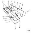
- three heating rods 5 which are evenly spaced are arranged. They are held by Tragringen 6, the ends of the heating rods 5 laterally over the tub.
- the tub 3 is a cuboid hollow body whose Top is completely open, leaving a rectangular circulating tub edge 9 is present, that of the edges the short and long side walls 10 of the tub 3 formed becomes.
- the heating rods 5, preferably consist of graphite, held in support rings 6. These are rectangular and have a cross section of the Heating rods 5 adapted inner opening 11 through which the respective end of a heating rod 5 inserted therethrough is.
- the outer edge of the support rings 6 is provided with a circumferential Groove 12 provided, which is about as wide as the Sheets are thick, from which the tub 3 and the lid. 8 are made.
- the heating elements 5 are on the tub. 3 placed, the tub rim 9 in the grooves 12 of the Support rings 6 is introduced.
- the lid 8 shown next to the tub 3 has the shape of a with a gable-roofed house, so has two rectangular side walls 13, two sloping ceilings 14 and two Gable walls 15.
- the sloping roofs 14 run in the ridge of Gabled roofs down to a slot together, the exit slot 16 acts for the steam generated in the housing.
- the side walls 13 of the lid 8 are approximately as high as the support rings 6 and have corresponding rectangular open-edged cutouts 17, the shape of the Support rings 6 are adjusted so that when the lid is put on is, the edge of the cutouts 17 in the groove 12th immersed in the support rings 6. With the lid 8 thus results in a closed housing, the across of three heating rods 5 is interspersed and that at the top via an exit slot 16 for the exit of the generated Steam has.
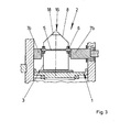
- FIG. 3 shows a Cross section through the evaporation device 2.
- the Contour of the formed by a tub 3 and a lid 8 Housing corresponds in cross section to a rectangle, on whose short side is a triangle attached.
- One third of the rectangular housing area becomes the housing crossed by the heating rods 5, which in cross section are rectangular and with their flat side down point.
- a fixed contact stamp on the left 7a for contacting the protruding from the housing to see an end of the heating element 5.
- a movable contact stamp 7b located at the other end of the out of the case outstanding heating rod 5 applies.
- the heating element 5 is connected to a power supply connected: He heats himself through the flowing Electricity on, with its heat energy in the form of radiant power in particular to that located in the tub 3 Material 4 is released, which then evaporates.
Landscapes
- Chemical & Material Sciences (AREA)
- Engineering & Computer Science (AREA)
- Organic Chemistry (AREA)
- Metallurgy (AREA)
- Mechanical Engineering (AREA)
- Materials Engineering (AREA)
- Chemical Kinetics & Catalysis (AREA)
- Physics & Mathematics (AREA)
- Toxicology (AREA)
- Health & Medical Sciences (AREA)
- General Physics & Mathematics (AREA)
- Theoretical Computer Science (AREA)
- Computing Systems (AREA)
- Computer Hardware Design (AREA)
- Mathematical Physics (AREA)
- Physical Vapour Deposition (AREA)
- Vaporization, Distillation, Condensation, Sublimation, And Cold Traps (AREA)
- Organic Low-Molecular-Weight Compounds And Preparation Thereof (AREA)
Priority Applications (1)
| Application Number | Priority Date | Filing Date | Title |
|---|---|---|---|
| PL04004928T PL1555334T3 (pl) | 2004-01-14 | 2004-03-03 | Urządzenie do odparowywania sublimowanych materiałów |
Applications Claiming Priority (2)
| Application Number | Priority Date | Filing Date | Title |
|---|---|---|---|
| DE102004001884A DE102004001884A1 (de) | 2004-01-14 | 2004-01-14 | Verdampfungseinrichtung für sublimierende Materialien |
| DE102004001884 | 2004-01-14 |
Publications (2)
| Publication Number | Publication Date |
|---|---|
| EP1555334A1 true EP1555334A1 (fr) | 2005-07-20 |
| EP1555334B1 EP1555334B1 (fr) | 2008-05-07 |
Family
ID=34609530
Family Applications (1)
| Application Number | Title | Priority Date | Filing Date |
|---|---|---|---|
| EP04004928A Expired - Lifetime EP1555334B1 (fr) | 2004-01-14 | 2004-03-03 | Installation de vaporisation pour la sublimation de matériaux |
Country Status (10)
| Country | Link |
|---|---|
| US (1) | US20050150975A1 (fr) |
| EP (1) | EP1555334B1 (fr) |
| JP (1) | JP2005200767A (fr) |
| KR (1) | KR100642057B1 (fr) |
| CN (1) | CN1333104C (fr) |
| AT (1) | ATE394520T1 (fr) |
| DE (2) | DE102004001884A1 (fr) |
| PL (1) | PL1555334T3 (fr) |
| RU (1) | RU2307877C2 (fr) |
| TW (1) | TWI269816B (fr) |
Families Citing this family (7)
| Publication number | Priority date | Publication date | Assignee | Title |
|---|---|---|---|---|
| JP5361467B2 (ja) * | 2009-03-13 | 2013-12-04 | 東京エレクトロン株式会社 | 気化器 |
| KR20140025795A (ko) * | 2012-08-22 | 2014-03-05 | 에스엔유 프리시젼 주식회사 | 선택적 선형 증발 장치 |
| KR102227546B1 (ko) * | 2014-01-20 | 2021-03-15 | 주식회사 선익시스템 | 대용량 증발원 및 이를 포함하는 증착장치 |
| CN104404451A (zh) * | 2014-12-16 | 2015-03-11 | 合肥鑫晟光电科技有限公司 | 蒸镀源和蒸镀装置 |
| CN105132866B (zh) * | 2015-09-08 | 2018-02-16 | 京东方科技集团股份有限公司 | 一种蒸镀机的加热源装置及蒸镀机 |
| EP3559306B1 (fr) * | 2016-12-22 | 2022-10-05 | Flisom AG | Source linéaire destinée au dépôt en phase vapeur dotée d'au moins trois éléments chauffants électriques |
| CN108330444A (zh) * | 2018-02-11 | 2018-07-27 | 常德金德新材料科技股份有限公司 | 一种制备硫化锌膜的方法 |
Citations (4)
| Publication number | Priority date | Publication date | Assignee | Title |
|---|---|---|---|---|
| JPS5943872A (ja) * | 1982-09-04 | 1984-03-12 | Konishiroku Photo Ind Co Ltd | 蒸発材料収容器 |
| EP0477474A1 (fr) * | 1990-09-28 | 1992-04-01 | Mitsubishi Jukogyo Kabushiki Kaisha | Appareillage pour dépôt sous vide en phase vapeur |
| EP0510259A1 (fr) * | 1991-04-03 | 1992-10-28 | Mitsubishi Jukogyo Kabushiki Kaisha | Appareil pour dépôt sous vide d'une substance sublimable |
| US5239611A (en) * | 1991-02-14 | 1993-08-24 | Hilmar Weinert | Series evaporator |
Family Cites Families (15)
| Publication number | Priority date | Publication date | Assignee | Title |
|---|---|---|---|---|
| US3041493A (en) * | 1950-08-30 | 1962-06-26 | Sylvania Electric Prod | Electron discharge device |
| US3027150A (en) * | 1958-03-10 | 1962-03-27 | Hoerder Huettenunion Ag | Apparatus for treating steel melts |
| GB918382A (en) * | 1960-11-29 | 1963-02-13 | Gen Electric Co Ltd | Improvements in or relating to the formation of thin films |
| JPS5048855U (fr) * | 1973-09-04 | 1975-05-14 | ||
| JPS5224050U (fr) * | 1975-08-08 | 1977-02-19 | ||
| US4045638A (en) * | 1976-03-09 | 1977-08-30 | Bing Chiang | Continuous flow heat treating apparatus using microwaves |
| DE2723581C2 (de) * | 1977-03-08 | 1984-11-29 | Techtransfer GmbH, 7000 Stuttgart | Verfahren zum aeroben Verrotten von tierischen Exkrementen oder Klärschlamm sowie Anlage zur Durchführung des Verfahrens |
| WO1989012117A1 (fr) * | 1988-05-31 | 1989-12-14 | Kievsky Politekhnichesky Institut Imeni 50-Letia V | Dispositif de depot sous vide de films |
| JPH0269961U (fr) * | 1988-11-17 | 1990-05-28 | ||
| US5182567A (en) * | 1990-10-12 | 1993-01-26 | Custom Metallizing Services, Inc. | Retrofittable vapor source for vacuum metallizing utilizing spatter reduction means |
| JP2583159B2 (ja) * | 1991-02-08 | 1997-02-19 | 株式会社小松製作所 | 流体加熱器 |
| FR2693480B1 (fr) * | 1992-07-08 | 1994-08-19 | Icbt Roanne | Dispositif de chauffage d'un fil en mouvement. |
| JPH11246963A (ja) * | 1998-03-05 | 1999-09-14 | Nikon Corp | 蒸着用ボートとそれを用いて成膜した光学薄膜 |
| JP2000248358A (ja) * | 1999-03-01 | 2000-09-12 | Casio Comput Co Ltd | 蒸着装置および蒸着方法 |
| US20050034847A1 (en) * | 2003-08-11 | 2005-02-17 | Robert Graham | Monolithic tube sheet and method of manufacture |
-
2004
- 2004-01-14 DE DE102004001884A patent/DE102004001884A1/de not_active Ceased
- 2004-03-03 AT AT04004928T patent/ATE394520T1/de not_active IP Right Cessation
- 2004-03-03 EP EP04004928A patent/EP1555334B1/fr not_active Expired - Lifetime
- 2004-03-03 DE DE502004007046T patent/DE502004007046D1/de not_active Expired - Lifetime
- 2004-03-03 PL PL04004928T patent/PL1555334T3/pl unknown
- 2004-03-08 TW TW093106035A patent/TWI269816B/zh not_active IP Right Cessation
- 2004-04-02 CN CNB2004100323466A patent/CN1333104C/zh not_active Withdrawn - After Issue
- 2004-04-21 KR KR1020040027333A patent/KR100642057B1/ko not_active Expired - Fee Related
- 2004-12-01 US US11/001,528 patent/US20050150975A1/en not_active Abandoned
- 2004-12-22 RU RU2004137526/02A patent/RU2307877C2/ru active
-
2005
- 2005-01-13 JP JP2005006628A patent/JP2005200767A/ja active Pending
Patent Citations (4)
| Publication number | Priority date | Publication date | Assignee | Title |
|---|---|---|---|---|
| JPS5943872A (ja) * | 1982-09-04 | 1984-03-12 | Konishiroku Photo Ind Co Ltd | 蒸発材料収容器 |
| EP0477474A1 (fr) * | 1990-09-28 | 1992-04-01 | Mitsubishi Jukogyo Kabushiki Kaisha | Appareillage pour dépôt sous vide en phase vapeur |
| US5239611A (en) * | 1991-02-14 | 1993-08-24 | Hilmar Weinert | Series evaporator |
| EP0510259A1 (fr) * | 1991-04-03 | 1992-10-28 | Mitsubishi Jukogyo Kabushiki Kaisha | Appareil pour dépôt sous vide d'une substance sublimable |
Non-Patent Citations (1)
| Title |
|---|
| PATENT ABSTRACTS OF JAPAN vol. 008, no. 134 (C - 230) 21 June 1984 (1984-06-21) * |
Also Published As
| Publication number | Publication date |
|---|---|
| JP2005200767A (ja) | 2005-07-28 |
| EP1555334B1 (fr) | 2008-05-07 |
| TWI269816B (en) | 2007-01-01 |
| CN1333104C (zh) | 2007-08-22 |
| US20050150975A1 (en) | 2005-07-14 |
| KR100642057B1 (ko) | 2006-11-10 |
| PL1555334T3 (pl) | 2008-10-31 |
| CN1641066A (zh) | 2005-07-20 |
| ATE394520T1 (de) | 2008-05-15 |
| TW200523382A (en) | 2005-07-16 |
| DE102004001884A1 (de) | 2005-08-11 |
| KR20050074882A (ko) | 2005-07-19 |
| DE502004007046D1 (de) | 2008-06-19 |
| RU2004137526A (ru) | 2006-06-10 |
| RU2307877C2 (ru) | 2007-10-10 |
Similar Documents
| Publication | Publication Date | Title |
|---|---|---|
| DE2810440C3 (de) | Mikrowellen-Bräunbehälter | |
| DE60318170T2 (de) | Vakuumverdampfer | |
| DE2605816A1 (de) | Geraet zur erwaermung von speisen u.ae. | |
| EP1555334B1 (fr) | Installation de vaporisation pour la sublimation de matériaux | |
| DE10346964B4 (de) | Geschirrspüler mit variabler Wärmedämmung | |
| DE2917841A1 (de) | Verdampfer fuer vakuumaufdampfanlagen | |
| EP1662017B1 (fr) | Dispositif pour l'évaporation de materiaux | |
| EP1102010A1 (fr) | Four à générateur de vapeur | |
| WO2017109622A1 (fr) | Ensemble de corps thermique et ensemble de paroi avant comprenant un ensemble de corps thermique de ce type | |
| DE2133119C3 (de) | Inkubator | |
| DE102007047330A1 (de) | Heizeinrichtung für eine Vakuumanlage | |
| EP1862564A1 (fr) | Dispositif d'évaporation des matériaux par un tube d'évaporation | |
| DE102013108411B4 (de) | Durchlauf-Substratbehandlungsanlage | |
| DE3643901A1 (de) | Beheiztes buegelelement, insbesondere mulde fuer eine muldenmangel | |
| EP1788113A1 (fr) | Evaporateur avec un réservoir pour recevoir le matériau à évaporer | |
| EP0269892B1 (fr) | Dispositif pour conserver la chaleur des aliments | |
| EP3513622B1 (fr) | Cassette en matière plastique avec dispositif de chauffage | |
| DE102013108403B4 (de) | Durchlauf-Substratbehandlungsanlage | |
| DE2402111B2 (de) | Reihenverdampfer für Vakuumbedampfungsanlagen | |
| DE4215385A1 (de) | Vakuum-Trockenschrank | |
| DE2820286A1 (de) | Durchlauf-heizeinrichtung fuer diskontinuierlichen betrieb als vorschalteinrichtung fuer vakuumbeschichtungsanlagen | |
| DE9210359U1 (de) | Vorrichtung für die Beschichtung von Substraten | |
| DE1805246C3 (de) | Vorrichtung zum Aufdampfen von Metallen unter Vakuum | |
| DE2221765A1 (de) | Kachelofen, insbesondere kaminungebundener elektrisch beheizbarer kachelofen | |
| EP1406056A1 (fr) | Assemblage d'une installation pour sécher un matériau chargé d'humidité |
Legal Events
| Date | Code | Title | Description |
|---|---|---|---|
| PUAI | Public reference made under article 153(3) epc to a published international application that has entered the european phase |
Free format text: ORIGINAL CODE: 0009012 |
|
| AK | Designated contracting states |
Kind code of ref document: A1 Designated state(s): AT BE BG CH CY CZ DE DK EE ES FI FR GB GR HU IE IT LI LU MC NL PL PT RO SE SI SK TR |
|
| AX | Request for extension of the european patent |
Extension state: AL LT LV MK |
|
| 17P | Request for examination filed |
Effective date: 20051111 |
|
| AKX | Designation fees paid |
Designated state(s): AT BE BG CH CY CZ DE DK EE ES FI FR GB GR HU IE IT LI LU MC NL PL PT RO SE SI SK TR |
|
| RAP1 | Party data changed (applicant data changed or rights of an application transferred) |
Owner name: APPLIED MATERIALS GMBH & CO. KG |
|
| GRAP | Despatch of communication of intention to grant a patent |
Free format text: ORIGINAL CODE: EPIDOSNIGR1 |
|
| GRAS | Grant fee paid |
Free format text: ORIGINAL CODE: EPIDOSNIGR3 |
|
| GRAA | (expected) grant |
Free format text: ORIGINAL CODE: 0009210 |
|
| AK | Designated contracting states |
Kind code of ref document: B1 Designated state(s): AT BE BG CH CY CZ DE DK EE ES FI FR GB GR HU IE IT LI LU MC NL PL PT RO SE SI SK TR |
|
| REG | Reference to a national code |
Ref country code: GB Ref legal event code: FG4D Free format text: NOT ENGLISH |
|
| REG | Reference to a national code |
Ref country code: CH Ref legal event code: EP |
|
| REG | Reference to a national code |
Ref country code: IE Ref legal event code: FG4D Free format text: LANGUAGE OF EP DOCUMENT: GERMAN |
|
| REF | Corresponds to: |
Ref document number: 502004007046 Country of ref document: DE Date of ref document: 20080619 Kind code of ref document: P |
|
| PG25 | Lapsed in a contracting state [announced via postgrant information from national office to epo] |
Ref country code: SI Free format text: LAPSE BECAUSE OF FAILURE TO SUBMIT A TRANSLATION OF THE DESCRIPTION OR TO PAY THE FEE WITHIN THE PRESCRIBED TIME-LIMIT Effective date: 20080507 |
|
| PG25 | Lapsed in a contracting state [announced via postgrant information from national office to epo] |
Ref country code: NL Free format text: LAPSE BECAUSE OF FAILURE TO SUBMIT A TRANSLATION OF THE DESCRIPTION OR TO PAY THE FEE WITHIN THE PRESCRIBED TIME-LIMIT Effective date: 20080507 Ref country code: ES Free format text: LAPSE BECAUSE OF FAILURE TO SUBMIT A TRANSLATION OF THE DESCRIPTION OR TO PAY THE FEE WITHIN THE PRESCRIBED TIME-LIMIT Effective date: 20080818 Ref country code: FI Free format text: LAPSE BECAUSE OF FAILURE TO SUBMIT A TRANSLATION OF THE DESCRIPTION OR TO PAY THE FEE WITHIN THE PRESCRIBED TIME-LIMIT Effective date: 20080507 |
|
| REG | Reference to a national code |
Ref country code: PL Ref legal event code: T3 |
|
| NLV1 | Nl: lapsed or annulled due to failure to fulfill the requirements of art. 29p and 29m of the patents act | ||
| REG | Reference to a national code |
Ref country code: IE Ref legal event code: FD4D |
|
| PG25 | Lapsed in a contracting state [announced via postgrant information from national office to epo] |
Ref country code: IE Free format text: LAPSE BECAUSE OF FAILURE TO SUBMIT A TRANSLATION OF THE DESCRIPTION OR TO PAY THE FEE WITHIN THE PRESCRIBED TIME-LIMIT Effective date: 20080507 Ref country code: PT Free format text: LAPSE BECAUSE OF FAILURE TO SUBMIT A TRANSLATION OF THE DESCRIPTION OR TO PAY THE FEE WITHIN THE PRESCRIBED TIME-LIMIT Effective date: 20081007 Ref country code: DK Free format text: LAPSE BECAUSE OF FAILURE TO SUBMIT A TRANSLATION OF THE DESCRIPTION OR TO PAY THE FEE WITHIN THE PRESCRIBED TIME-LIMIT Effective date: 20080507 Ref country code: SE Free format text: LAPSE BECAUSE OF FAILURE TO SUBMIT A TRANSLATION OF THE DESCRIPTION OR TO PAY THE FEE WITHIN THE PRESCRIBED TIME-LIMIT Effective date: 20080807 |
|
| PG25 | Lapsed in a contracting state [announced via postgrant information from national office to epo] |
Ref country code: SK Free format text: LAPSE BECAUSE OF FAILURE TO SUBMIT A TRANSLATION OF THE DESCRIPTION OR TO PAY THE FEE WITHIN THE PRESCRIBED TIME-LIMIT Effective date: 20080507 Ref country code: RO Free format text: LAPSE BECAUSE OF FAILURE TO SUBMIT A TRANSLATION OF THE DESCRIPTION OR TO PAY THE FEE WITHIN THE PRESCRIBED TIME-LIMIT Effective date: 20080507 |
|
| PLBE | No opposition filed within time limit |
Free format text: ORIGINAL CODE: 0009261 |
|
| STAA | Information on the status of an ep patent application or granted ep patent |
Free format text: STATUS: NO OPPOSITION FILED WITHIN TIME LIMIT |
|
| 26N | No opposition filed |
Effective date: 20090210 |
|
| PG25 | Lapsed in a contracting state [announced via postgrant information from national office to epo] |
Ref country code: EE Free format text: LAPSE BECAUSE OF FAILURE TO SUBMIT A TRANSLATION OF THE DESCRIPTION OR TO PAY THE FEE WITHIN THE PRESCRIBED TIME-LIMIT Effective date: 20080507 Ref country code: BG Free format text: LAPSE BECAUSE OF FAILURE TO SUBMIT A TRANSLATION OF THE DESCRIPTION OR TO PAY THE FEE WITHIN THE PRESCRIBED TIME-LIMIT Effective date: 20080807 |
|
| REG | Reference to a national code |
Ref country code: HU Ref legal event code: AG4A Ref document number: E004852 Country of ref document: HU |
|
| BERE | Be: lapsed |
Owner name: APPLIED MATERIALS G.M.B.H. & CO. KG Effective date: 20090331 |
|
| PG25 | Lapsed in a contracting state [announced via postgrant information from national office to epo] |
Ref country code: CZ Free format text: LAPSE BECAUSE OF NON-PAYMENT OF DUE FEES Effective date: 20090303 Ref country code: MC Free format text: LAPSE BECAUSE OF NON-PAYMENT OF DUE FEES Effective date: 20090331 |
|
| REG | Reference to a national code |
Ref country code: CH Ref legal event code: PL |
|
| REG | Reference to a national code |
Ref country code: FR Ref legal event code: ST Effective date: 20091130 |
|
| PG25 | Lapsed in a contracting state [announced via postgrant information from national office to epo] |
Ref country code: HU Free format text: LAPSE BECAUSE OF NON-PAYMENT OF DUE FEES Effective date: 20090304 Ref country code: LI Free format text: LAPSE BECAUSE OF NON-PAYMENT OF DUE FEES Effective date: 20090331 Ref country code: CH Free format text: LAPSE BECAUSE OF NON-PAYMENT OF DUE FEES Effective date: 20090331 |
|
| PG25 | Lapsed in a contracting state [announced via postgrant information from national office to epo] |
Ref country code: BE Free format text: LAPSE BECAUSE OF NON-PAYMENT OF DUE FEES Effective date: 20090331 |
|
| PG25 | Lapsed in a contracting state [announced via postgrant information from national office to epo] |
Ref country code: FR Free format text: LAPSE BECAUSE OF NON-PAYMENT OF DUE FEES Effective date: 20091123 |
|
| PG25 | Lapsed in a contracting state [announced via postgrant information from national office to epo] |
Ref country code: AT Free format text: LAPSE BECAUSE OF NON-PAYMENT OF DUE FEES Effective date: 20090303 |
|
| REG | Reference to a national code |
Ref country code: PL Ref legal event code: LAPE |
|
| PG25 | Lapsed in a contracting state [announced via postgrant information from national office to epo] |
Ref country code: PL Free format text: LAPSE BECAUSE OF NON-PAYMENT OF DUE FEES Effective date: 20090303 |
|
| PG25 | Lapsed in a contracting state [announced via postgrant information from national office to epo] |
Ref country code: GR Free format text: LAPSE BECAUSE OF FAILURE TO SUBMIT A TRANSLATION OF THE DESCRIPTION OR TO PAY THE FEE WITHIN THE PRESCRIBED TIME-LIMIT Effective date: 20080808 |
|
| PG25 | Lapsed in a contracting state [announced via postgrant information from national office to epo] |
Ref country code: LU Free format text: LAPSE BECAUSE OF NON-PAYMENT OF DUE FEES Effective date: 20090303 |
|
| PG25 | Lapsed in a contracting state [announced via postgrant information from national office to epo] |
Ref country code: TR Free format text: LAPSE BECAUSE OF FAILURE TO SUBMIT A TRANSLATION OF THE DESCRIPTION OR TO PAY THE FEE WITHIN THE PRESCRIBED TIME-LIMIT Effective date: 20080507 |
|
| PG25 | Lapsed in a contracting state [announced via postgrant information from national office to epo] |
Ref country code: CY Free format text: LAPSE BECAUSE OF FAILURE TO SUBMIT A TRANSLATION OF THE DESCRIPTION OR TO PAY THE FEE WITHIN THE PRESCRIBED TIME-LIMIT Effective date: 20080507 |
|
| REG | Reference to a national code |
Ref country code: DE Ref legal event code: R082 Ref document number: 502004007046 Country of ref document: DE Representative=s name: ZIMMERMANN & PARTNER PATENTANWAELTE MBB, DE Ref country code: DE Ref legal event code: R082 Ref document number: 502004007046 Country of ref document: DE Representative=s name: ZIMMERMANN & PARTNER, DE |
|
| PGFP | Annual fee paid to national office [announced via postgrant information from national office to epo] |
Ref country code: GB Payment date: 20190320 Year of fee payment: 16 Ref country code: IT Payment date: 20190325 Year of fee payment: 16 Ref country code: DE Payment date: 20190321 Year of fee payment: 16 |
|
| REG | Reference to a national code |
Ref country code: DE Ref legal event code: R119 Ref document number: 502004007046 Country of ref document: DE |
|
| PG25 | Lapsed in a contracting state [announced via postgrant information from national office to epo] |
Ref country code: DE Free format text: LAPSE BECAUSE OF NON-PAYMENT OF DUE FEES Effective date: 20201001 |
|
| GBPC | Gb: european patent ceased through non-payment of renewal fee |
Effective date: 20200303 |
|
| PG25 | Lapsed in a contracting state [announced via postgrant information from national office to epo] |
Ref country code: GB Free format text: LAPSE BECAUSE OF NON-PAYMENT OF DUE FEES Effective date: 20200303 |
|
| PG25 | Lapsed in a contracting state [announced via postgrant information from national office to epo] |
Ref country code: IT Free format text: LAPSE BECAUSE OF NON-PAYMENT OF DUE FEES Effective date: 20200303 |