EP1555376A1 - Profilé composite - Google Patents
Profilé composite Download PDFInfo
- Publication number
- EP1555376A1 EP1555376A1 EP05000249A EP05000249A EP1555376A1 EP 1555376 A1 EP1555376 A1 EP 1555376A1 EP 05000249 A EP05000249 A EP 05000249A EP 05000249 A EP05000249 A EP 05000249A EP 1555376 A1 EP1555376 A1 EP 1555376A1
- Authority
- EP
- European Patent Office
- Prior art keywords
- joining
- profile
- wall
- longitudinal direction
- connection
- Prior art date
- Legal status (The legal status is an assumption and is not a legal conclusion. Google has not performed a legal analysis and makes no representation as to the accuracy of the status listed.)
- Withdrawn
Links
Images


Classifications
-
- E—FIXED CONSTRUCTIONS
- E06—DOORS, WINDOWS, SHUTTERS, OR ROLLER BLINDS IN GENERAL; LADDERS
- E06B—FIXED OR MOVABLE CLOSURES FOR OPENINGS IN BUILDINGS, VEHICLES, FENCES OR LIKE ENCLOSURES IN GENERAL, e.g. DOORS, WINDOWS, BLINDS, GATES
- E06B3/00—Window sashes, door leaves, or like elements for closing wall or like openings; Layout of fixed or moving closures, e.g. windows in wall or like openings; Features of rigidly-mounted outer frames relating to the mounting of wing frames
- E06B3/04—Wing frames not characterised by the manner of movement
- E06B3/263—Frames with special provision for insulation
- E06B3/26301—Frames with special provision for insulation with prefabricated insulating strips between two metal section members
- E06B3/26305—Connection details
- E06B2003/26309—Connection details using glue
-
- E—FIXED CONSTRUCTIONS
- E06—DOORS, WINDOWS, SHUTTERS, OR ROLLER BLINDS IN GENERAL; LADDERS
- E06B—FIXED OR MOVABLE CLOSURES FOR OPENINGS IN BUILDINGS, VEHICLES, FENCES OR LIKE ENCLOSURES IN GENERAL, e.g. DOORS, WINDOWS, BLINDS, GATES
- E06B3/00—Window sashes, door leaves, or like elements for closing wall or like openings; Layout of fixed or moving closures, e.g. windows in wall or like openings; Features of rigidly-mounted outer frames relating to the mounting of wing frames
- E06B3/04—Wing frames not characterised by the manner of movement
- E06B3/263—Frames with special provision for insulation
- E06B3/26301—Frames with special provision for insulation with prefabricated insulating strips between two metal section members
- E06B3/26305—Connection details
- E06B2003/26314—Provisions for reducing the shift between the strips and the metal section members
-
- E—FIXED CONSTRUCTIONS
- E06—DOORS, WINDOWS, SHUTTERS, OR ROLLER BLINDS IN GENERAL; LADDERS
- E06B—FIXED OR MOVABLE CLOSURES FOR OPENINGS IN BUILDINGS, VEHICLES, FENCES OR LIKE ENCLOSURES IN GENERAL, e.g. DOORS, WINDOWS, BLINDS, GATES
- E06B3/00—Window sashes, door leaves, or like elements for closing wall or like openings; Layout of fixed or moving closures, e.g. windows in wall or like openings; Features of rigidly-mounted outer frames relating to the mounting of wing frames
- E06B3/04—Wing frames not characterised by the manner of movement
- E06B3/263—Frames with special provision for insulation
- E06B3/2632—Frames with special provision for insulation with arrangements reducing the heat transmission, other than an interruption in a metal section
- E06B2003/26332—Arrangements reducing the heat transfer in the glazing rabbet or the space between the wing and the casing frame
-
- E—FIXED CONSTRUCTIONS
- E06—DOORS, WINDOWS, SHUTTERS, OR ROLLER BLINDS IN GENERAL; LADDERS
- E06B—FIXED OR MOVABLE CLOSURES FOR OPENINGS IN BUILDINGS, VEHICLES, FENCES OR LIKE ENCLOSURES IN GENERAL, e.g. DOORS, WINDOWS, BLINDS, GATES
- E06B3/00—Window sashes, door leaves, or like elements for closing wall or like openings; Layout of fixed or moving closures, e.g. windows in wall or like openings; Features of rigidly-mounted outer frames relating to the mounting of wing frames
- E06B3/04—Wing frames not characterised by the manner of movement
- E06B3/263—Frames with special provision for insulation
- E06B2003/26349—Details of insulating strips
- E06B2003/2635—Specific form characteristics
- E06B2003/26352—Specific form characteristics hollow
- E06B2003/26356—Honeycomb
-
- E—FIXED CONSTRUCTIONS
- E06—DOORS, WINDOWS, SHUTTERS, OR ROLLER BLINDS IN GENERAL; LADDERS
- E06B—FIXED OR MOVABLE CLOSURES FOR OPENINGS IN BUILDINGS, VEHICLES, FENCES OR LIKE ENCLOSURES IN GENERAL, e.g. DOORS, WINDOWS, BLINDS, GATES
- E06B3/00—Window sashes, door leaves, or like elements for closing wall or like openings; Layout of fixed or moving closures, e.g. windows in wall or like openings; Features of rigidly-mounted outer frames relating to the mounting of wing frames
- E06B3/04—Wing frames not characterised by the manner of movement
- E06B3/263—Frames with special provision for insulation
- E06B2003/26349—Details of insulating strips
- E06B2003/26369—Specific material characteristics
- E06B2003/26378—Specific material characteristics comprising foam
-
- E—FIXED CONSTRUCTIONS
- E06—DOORS, WINDOWS, SHUTTERS, OR ROLLER BLINDS IN GENERAL; LADDERS
- E06B—FIXED OR MOVABLE CLOSURES FOR OPENINGS IN BUILDINGS, VEHICLES, FENCES OR LIKE ENCLOSURES IN GENERAL, e.g. DOORS, WINDOWS, BLINDS, GATES
- E06B3/00—Window sashes, door leaves, or like elements for closing wall or like openings; Layout of fixed or moving closures, e.g. windows in wall or like openings; Features of rigidly-mounted outer frames relating to the mounting of wing frames
- E06B3/04—Wing frames not characterised by the manner of movement
- E06B3/263—Frames with special provision for insulation
- E06B2003/26349—Details of insulating strips
- E06B2003/26387—Performing extra functions
- E06B2003/26389—Holding sealing strips or forming sealing abutments
-
- E—FIXED CONSTRUCTIONS
- E06—DOORS, WINDOWS, SHUTTERS, OR ROLLER BLINDS IN GENERAL; LADDERS
- E06B—FIXED OR MOVABLE CLOSURES FOR OPENINGS IN BUILDINGS, VEHICLES, FENCES OR LIKE ENCLOSURES IN GENERAL, e.g. DOORS, WINDOWS, BLINDS, GATES
- E06B3/00—Window sashes, door leaves, or like elements for closing wall or like openings; Layout of fixed or moving closures, e.g. windows in wall or like openings; Features of rigidly-mounted outer frames relating to the mounting of wing frames
- E06B3/54—Fixing of glass panes or like plates
- E06B3/58—Fixing of glass panes or like plates by means of borders, cleats, or the like
- E06B3/62—Fixing of glass panes or like plates by means of borders, cleats, or the like of rubber-like elastic cleats
- E06B2003/6238—Fixing of glass panes or like plates by means of borders, cleats, or the like of rubber-like elastic cleats having extra functions
- E06B2003/6244—Fixing of glass panes or like plates by means of borders, cleats, or the like of rubber-like elastic cleats having extra functions with extra parts sealing against the bottom of the glazing rebate or against the edge of the pane
Definitions
- the present invention relates to a composite profile arrangement, and more particularly on a composite profile arrangement for window, door and facade elements.
- Composite profiles for window, door and facade elements of the type in question have two profile parts, an outer profile and an inner profile, by one or more as insulating trained connecting parts are connected to each other, on. 90% of today conventional composite profiles are made of aluminum, the connection of the profile parts and the insulating elements is made by curling, as for example in the DE 1 101 734 is described.
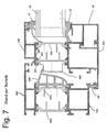
- Fig. 7 shows an example of such a composite profile using the example of window elements.
- An insulating glass pane 63 is held between seals 61, 62 in a window frame, which is formed of composite profiles, namely a movable composite profile (casement) and a stationary, e.g. building-side, composite profile.
- the movable composite profile has a profile part 200 (inner profile) formed over two as connecting parts Insulating elements 400, 500 is connected to a further profile part 300 (outer profile), on.
- a further profile part 60 is attached, via the seals 61, 62nd the insulating glass pane 63 on the composite profile formed from the parts 200, 300, 400, 500 holds.
- the building-side part of the window frame is made of another composite profile the profile parts 700, 800, via the formed as connecting parts insulating 900, 900 are formed, formed.
- the seals 65, 640 seal the gap between the two composite profiles.
- Fig. 7 is the example of the connection of the profile part 300 with the connecting part 500 a rolled connection shown.
- the profile part 300 is made like the profile parts 200, 700, 800 made of aluminum.
- a cross-section dovetailed Kunststoff Kunststoffssteiltagens Stud 501 is by positive engagement in a in Cross-section dovetail-shaped groove held by the connecting portion 301, 302 is formed.
- the one side wall 301 of the profile part connecting portion is after the Insertion of the connection part connection area 501 into the at this time not yet dovetail-shaped groove pressed toward the other wall 302 by rolling, as described for example in DE 1 101 734.
- the thickness of the composite profile or its elements in the direction in which the profile parts opposite is the so-called depth.
- the curling requires a profile design, in which only about 50% of the overall depth of the composite profile can be formed by the insulating elements. This reduces at the same depth of the Composite profiles the achievable thermal values.
- the wall thicknesses must be for inner profile parts and outer profile parts made of aluminum for a safe rolling process be greater than is necessary for the static strength.
- the depth of the composite profile grows strong. The result is that, for example, windows can no longer be opened with turn-tilt fittings with small joining widths.
- EP 0 085 410 A2 discloses another composite profile produced by rolling in which a supplemental material such as an adhesive for additional assurance of the connection is used.
- US 2003/0217818 A1 discloses a folding device (such as a Swivel fitting) for a room divider or a room finish (like a door), the composite profiles used.
- US 4,338,753 discloses an arrangement for connecting two profile parts, in which a cavity is filled with a curable filler.
- DE 26 50 944 A1 discloses a composite profile for window and Fassedenkonstru ashameden, in which the connection between the inner profile and the outer profile by a connecting web and a curable filler is produced and in the relative movements of the profiles and of the connecting web in the longitudinal direction of the same are possible.
- DE 30 33 206 A1 discloses a composite profile arrangement according to the preamble of the claim 1, in which a positive connection of protrusions and a curable filler the problem the shear strength in the longitudinal direction triggers.
- the shear strength in the longitudinal direction of the composite profile also in case of aging-related failure of the adhesion between the hardened bonding compound and the profile parts and / or the connecting part ensured by that on the cured compound a positive connection between positive locking elements such the first and second retaining elements is made and remains.
- This positive connection exists in all directions and not just in the longitudinal direction. Since no more curling necessary is, all materials such as aluminum, wood, plastic, steel in any combination be used for the profile parts.
- there are constructive limitations that were required by the curling away so that both the proportion of profile parts on the Bautiefe the composite profile can be reduced as well as the arrangement of the profile part connection areas and the connector connection areas without the geometric limitations, which are forced by curling, are possible.
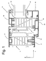
- Fig. 1 shows a window frame with composite profiles according to embodiments of the invention.
- the composite profiles extend in their longitudinal direction perpendicular to the paper plane from Fig. 1.
- the window frame has two composite profiles.
- a first composite profile 10 has a first profile part 20 (inner profile, i.e. the profile, for example on the inside of the building and a second profile part 30 (outer profile, i.e. the profile, e.g. placed on the outside of the building).
- the first profile part 20 is through a Insulating element, which is designed as a first connecting part 40, with the second profile part 30 connected.
- the connection of the first profile part and the second profile part through the first Connecting element is hardened by a compound 50 such as a hardened Cast resin or the like produced in a manner described in detail below.
- a compound 50 such as a hardened Cast resin or the like produced in a manner described in detail below.
- the parts 20, 30, 40 form the first composite profile 10.
- another profile member 60 is fixed such that an insulating glass pane 63 between seals 61, 62 is held on this first composite profile 10.
- the construction unit thus formed forms the moving part of a window frame.
- the building-side part of the window frame is formed by a second composite profile 11, that of a third profile part 11 and a fourth profile part 21, which has an insulating element , which is formed as a second connecting part 41, are connected.
- the gap between the two composite profiles 10, 11 is closed by the seals 64, 65 Condition of the window sealed.
- the connection of the parts 21, 31 and 41 will turn made in the manner described later by a curable bonding compound 50.
- the Construction depth of the composite profiles or their elements designates the overall depth in the transverse direction.
- the direction perpendicular to the transverse direction and perpendicular to the longitudinal direction will be described below as horizontal direction y (from left to right in Fig. 1).
- the definitions of Longitudinal direction, the transverse direction and the horizontal direction apply to all figures and the description of all embodiments and modifications.
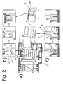
- FIG. 2 the view from Fig. 1 is shown in view a), and in view b) is an enlarged Partial view of a detail, which is marked by border in view a), in a sequence of steps of assembly and the final state shown, and in view c) is the enlarged Partial view of the other bordered detail shown in view a).
- the first profile part 20 has a first profile part connection area, which in Fig. 2a) in the border is shown.
- This first profile part connection region extends over at least a portion of the length of the first profile part 20 in the longitudinal direction, preferably over the entire length of the first profile part.
- the first profile part connection area has a joining recess 22 which extends in the longitudinal direction.
- the joining recess becomes formed by a recess bottom 22b and two walls 23, 24 extending from the recess bottom 22 protrude substantially in the transverse direction, and has a substantially U-shaped or similar cross-section, which is open on one side so that the Depth direction of the joining recess substantially in the same direction as the transverse direction extends, i. is substantially parallel to this, on ..
- Fig. 1 Embodiment is one of the two walls, namely the wall 24, free-standing.
- the volume the joining recess 22 corresponds to the volume of the recess bottom 22 b, the two walls 23, 24 and a line that is horizontal in the upper edge of the freestanding Wall 24 touches, is limited.
- First positive locking elements are as holding elements 25 in the form of tooth-like projections formed on one of the two walls 23, 24.
- three longitudinally arranged rows of projections 25 are provided. The majority of projections has in the longitudinal direction at a distance from each other.
- the first connection part 40 has a first connection part connection portion, which is formed by a joining projection 47.
- the joining projection is designed as a projection, since he to introduce into the FügeausEnglishung for connecting the profile part and the connecting part is, i. must project from the connecting part at least insofar as such Introduction is possible.
- On one side of the joining projection 47 are positive locking elements formed as a second holding elements 45 in the form of protrusions.
- Fig. 2 Embodiment again are three longitudinally arranged rows of projections 45, which have a distance from each other in the longitudinal direction provided.
- the joining projection 47 In the assembled state (the illustration on the far right in view c)) is the joining projection 47 inserted into the FügeausEnglishung 22, the first and second formed as projections Retaining elements 25, 45 face each other and overlap seen in the longitudinal direction not, and the joining recess or more precisely the gap between the first holding elements 25 having wall 23 and the second holding elements 45 having Joining projection 47 is connected to the cured bonding compound 50, which before insertion in Fügeaus supraung 22 was filled in uncured state, filled.
- the first connection part connection area in addition, extending in the longitudinal direction parallel to the joining projection 47 Wall 48 up. Between the joining projection 47 and the additional wall 48 is a Interspace 49 is formed.
- the width (in the horizontal direction) of the space 49 is dimensioned so that it is minimally smaller than or equal to the width (in the horizontal Direction) of the freestanding wall 24.
- the freestanding wall 24 is on the Side of the joining recess 24 is arranged, which is turned to the outside of the profile part, i.e. the potentially visible side, if at least two connection areas per respective Profile part / connecting part are present.
- This arrangement ensures that that any excess of the curable material or contamination with this, during or after the insertion of the joining projection in the FügeeausNeillung arises, remains invisible from outside the composite profile. That obviously also applies to all other connection areas of the corresponding profile parts / connecting parts.
- the second profile part 30 has a second profile part connection area, which in view b) is shown in greater detail.
- This second profile part connecting region has a joining projection 37, on the interlocking elements as the second holding elements 35 in the form of Projections are provided in the same manner as on the joining projection 47.
- the first Connector 40 has a second connector connection area, which in view b) is also shown in detail.
- This second connection part connection area has a joining recess 42, which in a similar manner as the joining recess 22nd by a recess bottom 42b and two longitudinally extending walls 43, 44 is formed.
- On the one wall 44 are positive locking elements as the first holding elements in Shape of projections 45 in the same manner as the projections 25 are provided.
- the Positive engagement between the second profile part 30 and the first connection part 40 is in the same way as with respect to the positive connection between the first profile part 20 and after the curing of the bonding compound 50 produced.
- a holding device is in the detail shown in view b) by the freestanding Wall 34, which is formed parallel to the joining projection 37, and another free-standing Wall 46, which is formed parallel to the wall 44 outside of the joining recess 42 is formed.
- the walls 44, 46 form a gap 49 whose width is minimally smaller than which is equal to or equal to the thickness of the freestanding wall 34, so that analogous to the previously described Retaining a holding force between these walls after insertion of the joining projection 37 is obtained in the joining recess 32.
- the holding device in the first embodiment shown in FIGS. 1 and 2 thus consists of a freestanding wall (which is a clamped element) on one component, and two parallel walls (which constitute clamping elements) on a second component, the have a distance which is slightly smaller than or equal to the thickness of the other freestanding wall is so that after inserting the other freestanding wall in This gap is obtained a holding force by the friction.
- a freestanding wall which is a clamped element
- two parallel walls which constitute clamping elements
- the first connecting part 40 has four Connection connection areas. There are two connection part connection areas each associated with the first profile part 20 and the second profile part 30. The two profile parts have corresponding to two profile part connection areas, so that a total of four Connection area pairs are present.
- connection areas are not necessarily in lie in the horizontal direction (see the connection areas between the first profile part 20 and connecting part 40).
- All joining recesses are identically oriented, in other words, in the same direction, i.e. their depth direction is substantially parallel (i.e. deviation ⁇ 30 °, or ⁇ 20 °, or ⁇ 10 ° or preferably ⁇ 5 °, or more preferably ⁇ 2 °,) to the transverse direction and they all have their mouths open on the same side in the depth direction.
- each holding device is a holding device for each pair of connection areas of the corresponding profile and connection parts, arranged so that they are on the outside of the corresponding connecting portion are positioned.
- excess resin compound
- the holding device is thus also a "compound compound cover device” or a “bonding compound sealing device”.
- the additional or alternative functions The covering or sealing of the connecting mass are not affected by the function of the Keep limited. If the holding force is not used to hold the parts until the hardening of the Connection mass sufficient or for safety in addition to external holding devices are used, then the sealing function is still maintained.
- connection areas There are basically two types of connection areas, namely a first type, the has the joining recess, such as the first profile part connecting portion and the second Joining portion connecting portion, and a second type having the joining protrusion such as the first connection part connection area and the second profile part connection area.
- connection areas of the same type are within a composite profile all the same orientation.
- the proportion of the first connection part 40, i. of the insulating element, at the depth is much larger than in the prior art. This is under Another possible because the construction is no longer the high, occurring during rolling Forces etc. must record.
- the joining recess serves as a reservoir for the uncured compound. It should only be ensured that the filled volume of the compound does not exceed the volume of the joining recess.
- the volume is the filled compound below the volume, after deduction of the volume the volume of the inserted joining projection still remains in the joining recess (see Fig. 2b), right figure). But at least the volume is below the volume, the between the inserted joining projection and the opposite wall of the joining recess remains (see Fig. 2c), right figure).
- FIG. 1 Another advantage of the embodiment shown in Figs. 1 and 2 is that the joining the components are transversely, i. e. that no pushing in as well any kind of projections, components, dovetails, fasteners or similar must be done in the longitudinal direction of the composite profiles, as this in conventional Solutions with curling and many other conventional solutions is the case. This is solved another tolerance problem.
- the profile parts 20, 21, 30, 31 all materials can be freely selected, e.g. Wood, steel, plastic, aluminum. It can e.g. weather-resistant for the outer profile Materials and for the inner profile more selected by appearance materials be used.
- the insulating elements selected as connecting part are made of a good heat-insulating plastic, e.g. Polyamide or PET formed.
- the curable bonding compound may be a cast resin such as PUR, PIR or an epoxy resin system be.
- the resin should preferably be powder-coatable, i. a temperature of 200 to 220 ° C survive for 20 to 30 minutes and / or it should preferably be resistant to cleaning baths be as they are used in anodizing.
- At least the visible surfaces of the connector 40 are conductive such that the resistance is less than 10 -9 ⁇ . This serves to allow the materials to be coated. This conductivity is achieved either with an applied conductive primer and / or by introducing a conductive material into the insulating element.
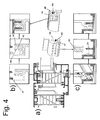
- a method for producing the first composite profile is shown schematically. First, the first profile part 20 and the second profile part 30 and the first connection part 40 provided. Then the (identically oriented) joining recesses of the first profile part and the first connection part with a predetermined volume of the curable Bonding compound 50, e.g. via filling nozzles 102 of a corresponding filling machine 101 (see Fig. 3a)). Then, in the transverse direction, the (identically oriented) Joining projections of the first connection part and the second profile part in the Fügeeausappel introduced (see Fig. 3b)).
- FIG. 4 is a modification of the embodiments shown in FIGS. 1 and 2. Of the only difference is that the holding devices are designed differently. At the modification shown in Fig. 4 are the spaces 49 in the holding means so formed so that they are in the direction of the opening in cross-section perpendicular to the longitudinal direction rejuvenate. On the gap facing inner sides of the walls 44, 46 and 47, 48 are knurls or rasters 46r, 48r formed. On the in the spaces between freestanding walls to be inserted are corresponding knurls or grids, which are not shown formed.
- the holding force can be essential be increased and keeping it safer.
- FIG. 5 shows a further modification of the embodiments shown in FIGS. 1 and 2.
- the modification shown in Fig. 5 differs in that no holding devices are provided. In the embodiment shown in Fig. 5 it would still be possible to omit the freestanding wall 34 (see Fig. 5b)).
- Fig. 6 a further modification is shown.
- the first and second retaining elements are partially formed as knurling 25r, 45r. Even such knurling exists last End of protrusions and / or incisions and results in a suitable choice of the curable Joining compound the same effects and advantages as larger protrusions.
- the Profile parts 20 and 30 shown in FIG. 6 can be produced by bending a pre-knurled sheet, As shown in Fig. 6c, are produced in a simple manner.
- the first and / or second holding elements i. the projections and / or Incisions, also through reticular structures, screened structures, embossments, especially rough surface structures such as roughened wood, etc. are obtained.
- the orientation correspond the depth direction of the joining recess and the direction of protrusion of the Joining projection and the resulting direction of inserting the joining projection into the FügeeausEnglishung each of the transverse direction.
- this is the tolerance compensation possible.
- the tolerance compensation is of course also possible for an orientation of the depth direction the joining recess and the direction of protrusion of the joining projection and the resulting direction of insertion of ⁇ 90 ° relative to the transverse direction. But even with appropriate orientations and an insertion perpendicular to the transverse direction All advantages except tolerance compensation are obtained.
- the first, second and third materials of the claims can be freely chosen and are not limited to a single material.
- the third material have multiple materials, i. the connecting part may e.g. partly made of polyamide and partly made of PU foam, and / or the first profile part (first material) may be partially made of plastic and partially made of wood and / or the second Profile part (second material) may be formed partly of metal and partly of plastic be.
Landscapes
- Engineering & Computer Science (AREA)
- Civil Engineering (AREA)
- Structural Engineering (AREA)
- Wing Frames And Configurations (AREA)
Priority Applications (2)
| Application Number | Priority Date | Filing Date | Title |
|---|---|---|---|
| EP05000249A EP1555376A1 (fr) | 2004-01-19 | 2005-01-07 | Profilé composite |
| US11/038,765 US20050183351A1 (en) | 2004-01-19 | 2005-01-19 | Composite profiles suitable for insulating window units |
Applications Claiming Priority (3)
| Application Number | Priority Date | Filing Date | Title |
|---|---|---|---|
| EP04001031A EP1555375A1 (fr) | 2004-01-19 | 2004-01-19 | Profilé composite |
| EP04001031 | 2004-02-04 | ||
| EP05000249A EP1555376A1 (fr) | 2004-01-19 | 2005-01-07 | Profilé composite |
Publications (1)
| Publication Number | Publication Date |
|---|---|
| EP1555376A1 true EP1555376A1 (fr) | 2005-07-20 |
Family
ID=34621568
Family Applications (1)
| Application Number | Title | Priority Date | Filing Date |
|---|---|---|---|
| EP05000249A Withdrawn EP1555376A1 (fr) | 2004-01-19 | 2005-01-07 | Profilé composite |
Country Status (2)
| Country | Link |
|---|---|
| US (1) | US20050183351A1 (fr) |
| EP (1) | EP1555376A1 (fr) |
Cited By (19)
| Publication number | Priority date | Publication date | Assignee | Title |
|---|---|---|---|---|
| EP1710384A3 (fr) * | 2005-04-08 | 2007-07-11 | Expral, S.A. | Profilés d'étanchéité pour portes et fenêtres métalliques |
| DE102006061035B3 (de) * | 2006-12-22 | 2008-06-26 | Technoform Caprano Und Brunnhofer Gmbh & Co. Kg | Kunststoffprofil für Fenster-, Türen- und Fassadenelemente |
| DE102006059854A1 (de) | 2006-12-15 | 2008-07-03 | Technoform Caprano Und Brunnhofer Gmbh & Co. Kg | Armiertes Kunststoffprofil für Fenster-, Türen- und Fassadenelemente |
| EP2011945A1 (fr) * | 2007-07-06 | 2009-01-07 | Reynaers Aluminium, naamloze vennootschap | Profilé composite pour porte, fenêtre ou similaire |
| BE1017676A3 (nl) * | 2007-07-06 | 2009-03-03 | Reynaers Aluminium Nv | Verbeterd samengesteld profiel voor ramen, deuren of dergelijke. |
| DE102008008343A1 (de) * | 2008-02-08 | 2009-08-13 | Aluplast Gmbh | Profil für Fenster- oder Türrahmen |
| BE1018161A3 (nl) * | 2007-07-06 | 2010-06-01 | Reynaers Aluminium Nv | Verbeterd samengesteld profiel voor ramen, deuren of dergelijke. |
| DE102009037851A1 (de) | 2009-08-18 | 2011-02-24 | Technoform Caprano Und Brunnhofer Gmbh & Co. Kg | Mehrteiliger Isolierkörper zur thermischen Trennung in Profilen für Fenster-, Türen- und Fassadenelemente, Profil für Fenster-, Türen- und Fassadenelemente sowie Herstellungsverfahren für den Isolierkörper und das Profil |
| EP2314816A1 (fr) * | 2009-10-17 | 2011-04-27 | Christian Meyer | Technologie de profilé composite en d'aluminium destinée à relier des profilés en plastique et en aluminium à des profilés complet pour la fabrication de fenêtres et de portes en aluminium |
| WO2011154300A3 (fr) * | 2010-06-07 | 2012-06-07 | Voestalpine Krems Gmbh | Profilé à rupture de pont thermique |
| FR2973822A1 (fr) * | 2011-04-06 | 2012-10-12 | Cibox | Porte, dormant de porte et bloc-porte a performances thermiques ameliorees |
| AT511727A1 (de) * | 2011-07-22 | 2013-02-15 | Josko Fenster Und Tueren Gmbh | Fensterrahmen aus faserverstärktem kunststoff |
| AT511742A1 (de) * | 2011-07-22 | 2013-02-15 | Josko Fenster Und Tueren Gmbh | Vorsatzschale für fenster- oder türrahmen |
| FR2986554A1 (fr) * | 2012-02-02 | 2013-08-09 | Scer Rotation Ii | Systeme de menuiserie a rupture de pont thermique amelioree. |
| ITBA20130028A1 (it) * | 2013-04-16 | 2014-10-17 | Carmine Capece | Infisso per case passive munito di accoppiamento modulare intercambiabile sia sul lato esterno, sia sul lato interno |
| EP2549045A3 (fr) * | 2011-07-22 | 2014-11-05 | JOSKO Fenster und Türen GmbH | Panneau d'habillage pour fenêtres ou cadres de portes |
| WO2015007493A1 (fr) * | 2013-07-18 | 2015-01-22 | Maschinenbau Kitz Gmbh | Support pour un système de profilé |
| EP3002403A1 (fr) * | 2014-10-02 | 2016-04-06 | IFN-Holding AG | Élement de fenetre |
| RU241438U1 (ru) * | 2025-10-13 | 2026-02-24 | Общество С Ограниченной Ответственностью "Двери Нск" | Вставка дверного блока |
Families Citing this family (19)
| Publication number | Priority date | Publication date | Assignee | Title |
|---|---|---|---|---|
| US20080295451A1 (en) * | 2004-08-04 | 2008-12-04 | Erwin Brunnhofer | Blank for Spacer for Insulating Window Unit, Spacer for Insulating Window Unit, Insulating Window Unit and Method For Manufacturing a Spacer |
| DE202005019973U1 (de) * | 2004-09-09 | 2006-04-06 | Technoform Caprano Und Brunnhofer Gmbh & Co. Kg | Abstandshalterprofil für einen Abstandshalterrahmen für eine Isolierscheibeneinheit und Isolierscheibeneinheit |
| DE202007016649U1 (de) * | 2007-04-02 | 2008-04-30 | Technoform Caprano Und Brunnhofer Gmbh & Co. Kg | Leiterförmiger Isoliersteg für ein Verbundprofil für Fenster-, Türen- und Fassadenelemente und Verbundprofil für Fenster-, Türen- und Fassadenelemente |
| US8561365B2 (en) * | 2008-05-12 | 2013-10-22 | Hwd Acquisition, Inc. | Versatile hybrid window system |
| ATE532933T1 (de) * | 2008-06-18 | 2011-11-15 | Technoform Bautec Holding Gmbh | Verbundprofil für fenster-, türen-, oder fassadenelement mit vorbestimmten brandschutzeigenschaften und isoliersteg für ein verbundprofil mit brandschutzeigenschaften |
| GB2464558A (en) * | 2008-10-25 | 2010-04-28 | Bowater Building Products Ltd | Window frame with thermal break |
| IT1399707B1 (it) * | 2010-04-26 | 2013-04-26 | Palladio Spa | Serramento a taglio termico naturale |
| US20110318094A1 (en) | 2010-06-29 | 2011-12-29 | Vincent Hensley | Strut for connecting frames |
| US8683775B1 (en) * | 2012-09-07 | 2014-04-01 | Guardian Industries Corp. | Spacer system for installing vacuum insulated glass (VIG) window unit in window frame designed to accommodate thicker IG window unit |
| US10337233B2 (en) | 2014-08-29 | 2019-07-02 | Sierra Pacific Industries | Window system with interchangeable exterior accessory covers |
| US9828797B2 (en) * | 2014-10-07 | 2017-11-28 | The Regents Of The University Of California | Insulated window frame system |
| US10077598B2 (en) | 2015-08-28 | 2018-09-18 | Sierra Pacific Industries | Versatile hybrid window system |
| PL3170961T3 (pl) * | 2015-11-18 | 2018-11-30 | Knapp Gmbh | Profil do mocowania szyb |
| DE102016119580A1 (de) * | 2016-10-13 | 2018-04-19 | Ensinger Gmbh | Kunststoffprofil für ein Metall-Kunststoff-Verbundprofil |
| US20180135346A1 (en) * | 2016-11-15 | 2018-05-17 | Prestige Storefront Systems LLC | Modular storefront system |
| DE102017107684A1 (de) * | 2017-04-10 | 2018-10-11 | Ensinger Gmbh | Isolierprofil, insbesondere für die Herstellung von Fenster-, Türen- und Fassadenelementen, sowie Verfahren zu seiner Herstellung |
| US10550626B1 (en) * | 2018-11-30 | 2020-02-04 | Portella Industries, LLC | Metal frame and glass pane door element, window element, systems including same, and method for making same |
| DE102019106876A1 (de) * | 2019-03-18 | 2020-09-24 | Veka Ag | Rahmenprofil eines Blend- und/oder Flügelrahmens, sowie Verfahren zu dessen Herstellung und zur Eckverbindung |
| GB2591294A (en) | 2020-01-27 | 2021-07-28 | Garner Aluminium Extrusions Ltd | A method |
Citations (12)
| Publication number | Priority date | Publication date | Assignee | Title |
|---|---|---|---|---|
| DE1101734B (de) | 1955-08-29 | 1961-03-09 | Aluminium Ind Ag | Verfahren zur Herstellung eines Winkelprofils aus Metall mit einer Kunststoffzwischenlage in Stabform, insbesondere fuer Fenster- oder Tuerrahmen |
| DE1260105B (de) | 1964-06-30 | 1968-02-01 | Aluminium A G Menziken | Zusammengesetzter Profilstab fuer Fenster- und Fassadenkonstruktionen |
| US3393487A (en) | 1966-10-06 | 1968-07-23 | Reynolds Metals Co | Thermally insulating joint construction |
| DE7522009U (de) | 1975-11-06 | Wutoeschingen Aluminium | Mehrteiliger Rahmen, insbesondere Fenster- oder Türrahmen, mit Wärmeisolation | |
| DE2650944A1 (de) | 1976-11-08 | 1978-05-11 | Erich Schlenker | Zusammengesetzter profilstab fuer fenster- und fassadenkonstruktionen |
| DE3033206A1 (de) | 1980-09-03 | 1982-03-11 | Josef Gartner & Co, 8883 Gundelfingen | Verbundprofil |
| US4338753A (en) | 1979-05-14 | 1982-07-13 | Hef Technische Entwicklung Gmbh & Co. Kg | Arrangement for connecting two profile members, particularly channel members for metal windows |
| EP0085410A2 (fr) | 1982-02-03 | 1983-08-10 | Wilfried Ensinger | Procédé pour réunir les parties métalliques intérieures et extérieures d'un profile composite |
| EP0103272A2 (fr) | 1982-09-09 | 1984-03-21 | Integral Profilsystem AB | Isolation des profils d'aluminium dans un dispositif de fixation |
| DE3423712A1 (de) | 1983-06-30 | 1985-01-17 | Yoshida Kogyo K.K., Tokio/Tokyo | Verfahren zur herstellung einer waermeisolierenden profilschiene |
| DE10033861A1 (de) | 2000-07-12 | 2002-01-24 | Dieter Klose | Verbundprofil mit eingegossenem Distanzelement |
| US20030217818A1 (en) | 2002-05-24 | 2003-11-27 | Solarlux Aluminium Systeme Gmbh | Folding Device as Room Divider or Room Closure |
Family Cites Families (5)
| Publication number | Priority date | Publication date | Assignee | Title |
|---|---|---|---|---|
| US4128934A (en) * | 1970-07-06 | 1978-12-12 | Firma Julius & August Erbsloh | Method of making a thermally insulated window frame |
| US4377926A (en) * | 1978-02-23 | 1983-03-29 | Kawneer Company, Inc. | Framing member for curtain wall structures |
| DE3343687A1 (de) * | 1983-11-30 | 1985-06-05 | Schweizerische Aluminium Ag, Chippis | Metall-rahmenkonstruktion fuer fenster oder tueren |
| US5379518A (en) * | 1993-02-04 | 1995-01-10 | Caradon America Inc. | Method of producing a window sash |
| DE10033388A1 (de) * | 2000-07-08 | 2002-01-24 | Wicona Bausysteme Gmbh | Wärmegedämmtes Verbundprofil, insbesondere für Fenster, Türen, Fassaden und dergleichen |
-
2005
- 2005-01-07 EP EP05000249A patent/EP1555376A1/fr not_active Withdrawn
- 2005-01-19 US US11/038,765 patent/US20050183351A1/en not_active Abandoned
Patent Citations (13)
| Publication number | Priority date | Publication date | Assignee | Title |
|---|---|---|---|---|
| DE7522009U (de) | 1975-11-06 | Wutoeschingen Aluminium | Mehrteiliger Rahmen, insbesondere Fenster- oder Türrahmen, mit Wärmeisolation | |
| DE1101734B (de) | 1955-08-29 | 1961-03-09 | Aluminium Ind Ag | Verfahren zur Herstellung eines Winkelprofils aus Metall mit einer Kunststoffzwischenlage in Stabform, insbesondere fuer Fenster- oder Tuerrahmen |
| DE1260105B (de) | 1964-06-30 | 1968-02-01 | Aluminium A G Menziken | Zusammengesetzter Profilstab fuer Fenster- und Fassadenkonstruktionen |
| US3393487A (en) | 1966-10-06 | 1968-07-23 | Reynolds Metals Co | Thermally insulating joint construction |
| DE2650944A1 (de) | 1976-11-08 | 1978-05-11 | Erich Schlenker | Zusammengesetzter profilstab fuer fenster- und fassadenkonstruktionen |
| US4338753A (en) | 1979-05-14 | 1982-07-13 | Hef Technische Entwicklung Gmbh & Co. Kg | Arrangement for connecting two profile members, particularly channel members for metal windows |
| GB2083116A (en) * | 1980-09-03 | 1982-03-17 | Gartner & Co J | Composite bar |
| DE3033206A1 (de) | 1980-09-03 | 1982-03-11 | Josef Gartner & Co, 8883 Gundelfingen | Verbundprofil |
| EP0085410A2 (fr) | 1982-02-03 | 1983-08-10 | Wilfried Ensinger | Procédé pour réunir les parties métalliques intérieures et extérieures d'un profile composite |
| EP0103272A2 (fr) | 1982-09-09 | 1984-03-21 | Integral Profilsystem AB | Isolation des profils d'aluminium dans un dispositif de fixation |
| DE3423712A1 (de) | 1983-06-30 | 1985-01-17 | Yoshida Kogyo K.K., Tokio/Tokyo | Verfahren zur herstellung einer waermeisolierenden profilschiene |
| DE10033861A1 (de) | 2000-07-12 | 2002-01-24 | Dieter Klose | Verbundprofil mit eingegossenem Distanzelement |
| US20030217818A1 (en) | 2002-05-24 | 2003-11-27 | Solarlux Aluminium Systeme Gmbh | Folding Device as Room Divider or Room Closure |
Cited By (30)
| Publication number | Priority date | Publication date | Assignee | Title |
|---|---|---|---|---|
| EP1710384A3 (fr) * | 2005-04-08 | 2007-07-11 | Expral, S.A. | Profilés d'étanchéité pour portes et fenêtres métalliques |
| DE102006059854A1 (de) | 2006-12-15 | 2008-07-03 | Technoform Caprano Und Brunnhofer Gmbh & Co. Kg | Armiertes Kunststoffprofil für Fenster-, Türen- und Fassadenelemente |
| DE102006059854B4 (de) * | 2006-12-15 | 2010-04-01 | Technoform Caprano Und Brunnhofer Gmbh & Co. Kg | Armiertes Kunststoffprofil für Fenster-, Türen- und Fassadenelemente |
| US8286396B2 (en) | 2006-12-22 | 2012-10-16 | Technoform Bautec Holding Gmbh | Plastic profile for window, door and facade elements |
| DE102006061035B3 (de) * | 2006-12-22 | 2008-06-26 | Technoform Caprano Und Brunnhofer Gmbh & Co. Kg | Kunststoffprofil für Fenster-, Türen- und Fassadenelemente |
| WO2008077515A1 (fr) * | 2006-12-22 | 2008-07-03 | Technoform Caprano Und Brunnhofer Gmbh & Co. Kg | Profilé en matière plastique pour des éléments de fenêtre, de porte et de façade |
| DE102006061035C5 (de) * | 2006-12-22 | 2014-09-04 | Technoform Bautec Holding Gmbh | Kunststoffprofil für Fenster-, Türen- und Fassadenelemente |
| BE1017676A3 (nl) * | 2007-07-06 | 2009-03-03 | Reynaers Aluminium Nv | Verbeterd samengesteld profiel voor ramen, deuren of dergelijke. |
| BE1018161A3 (nl) * | 2007-07-06 | 2010-06-01 | Reynaers Aluminium Nv | Verbeterd samengesteld profiel voor ramen, deuren of dergelijke. |
| EP2011945A1 (fr) * | 2007-07-06 | 2009-01-07 | Reynaers Aluminium, naamloze vennootschap | Profilé composite pour porte, fenêtre ou similaire |
| DE102008008343A1 (de) * | 2008-02-08 | 2009-08-13 | Aluplast Gmbh | Profil für Fenster- oder Türrahmen |
| WO2011020548A1 (fr) | 2009-08-18 | 2011-02-24 | Technoform Caprano Und Brunnhofer Gmbh & Co. Kg | Élément isolant en plusieurs parties, destiné à l'isolation thermique et disposé dans des profilés d'éléments de fenêtre, de porte et de façade, profilés pour des éléments de fenêtre, de porte et de façade, procédés de fabrication de l'élément isolant et du profilé |
| DE102009037851A1 (de) | 2009-08-18 | 2011-02-24 | Technoform Caprano Und Brunnhofer Gmbh & Co. Kg | Mehrteiliger Isolierkörper zur thermischen Trennung in Profilen für Fenster-, Türen- und Fassadenelemente, Profil für Fenster-, Türen- und Fassadenelemente sowie Herstellungsverfahren für den Isolierkörper und das Profil |
| EP2314816A1 (fr) * | 2009-10-17 | 2011-04-27 | Christian Meyer | Technologie de profilé composite en d'aluminium destinée à relier des profilés en plastique et en aluminium à des profilés complet pour la fabrication de fenêtres et de portes en aluminium |
| WO2011154300A3 (fr) * | 2010-06-07 | 2012-06-07 | Voestalpine Krems Gmbh | Profilé à rupture de pont thermique |
| RU2592194C2 (ru) * | 2010-06-07 | 2016-07-20 | Фоестальпине Кремс Гмбх | Термически разделенный профиль |
| FR2973822A1 (fr) * | 2011-04-06 | 2012-10-12 | Cibox | Porte, dormant de porte et bloc-porte a performances thermiques ameliorees |
| AT511742A1 (de) * | 2011-07-22 | 2013-02-15 | Josko Fenster Und Tueren Gmbh | Vorsatzschale für fenster- oder türrahmen |
| EP2549045A3 (fr) * | 2011-07-22 | 2014-11-05 | JOSKO Fenster und Türen GmbH | Panneau d'habillage pour fenêtres ou cadres de portes |
| AT511727B1 (de) * | 2011-07-22 | 2015-11-15 | JOSKO Fenster und Türen GmbH | Fensterrahmen aus faserverstärktem kunststoff |
| AT511742B1 (de) * | 2011-07-22 | 2015-11-15 | JOSKO Fenster und Türen GmbH | Vorsatzschale für fenster- oder türrahmen |
| EP2549044A3 (fr) * | 2011-07-22 | 2016-07-13 | JOSKO Fenster und Türen GmbH | Cadre de fenêtre en une matière plastique renforcée par des fibres |
| AT511727A1 (de) * | 2011-07-22 | 2013-02-15 | Josko Fenster Und Tueren Gmbh | Fensterrahmen aus faserverstärktem kunststoff |
| FR2986554A1 (fr) * | 2012-02-02 | 2013-08-09 | Scer Rotation Ii | Systeme de menuiserie a rupture de pont thermique amelioree. |
| ITBA20130028A1 (it) * | 2013-04-16 | 2014-10-17 | Carmine Capece | Infisso per case passive munito di accoppiamento modulare intercambiabile sia sul lato esterno, sia sul lato interno |
| WO2015007493A1 (fr) * | 2013-07-18 | 2015-01-22 | Maschinenbau Kitz Gmbh | Support pour un système de profilé |
| EP3002403A1 (fr) * | 2014-10-02 | 2016-04-06 | IFN-Holding AG | Élement de fenetre |
| AT516308A1 (de) * | 2014-10-02 | 2016-04-15 | Ifn Holding Ag | Fensterelement |
| AT516308B1 (de) * | 2014-10-02 | 2017-08-15 | Ifn-Holding Ag | Fensterelement |
| RU241438U1 (ru) * | 2025-10-13 | 2026-02-24 | Общество С Ограниченной Ответственностью "Двери Нск" | Вставка дверного блока |
Also Published As
| Publication number | Publication date |
|---|---|
| US20050183351A1 (en) | 2005-08-25 |
Similar Documents
| Publication | Publication Date | Title |
|---|---|---|
| EP1555376A1 (fr) | Profilé composite | |
| EP2106491B2 (fr) | Profilé en matière plastique pour des éléments de fenêtre, de porte et de façade | |
| EP3712368B1 (fr) | Profilé de cadre d'un bâti dormant et/ou de cadre de battant ainsi que son procédé de fabrication | |
| EP0100991B1 (fr) | Profil composé | |
| EP0006431A1 (fr) | Panneau de construction creux en matière plastique extrudée | |
| EP0616107B1 (fr) | Raccord à onglet d'éléments profilés | |
| WO2008071445A1 (fr) | Profilé armé en matière plastique pour des éléments de fenêtre, de porte et de façade | |
| EP2576949A2 (fr) | Profile a rupture de pont thermique | |
| DE69734632T2 (de) | Wärmedämmender Trennprofilkörper zum Einsetzen zwischen Aluminiumprofilen zur Verwendung bei der Herstellung von Türen und Fenster | |
| EP0215456A1 (fr) | Profilé creux en matière plastique extrudée pour cadres de portes et fenêtres | |
| EP1070824A2 (fr) | Vantail de fenêtre, notamment en matière plastique, pourvue d'au moins une vitre | |
| EP0875653A2 (fr) | Elément isolant avec au moins deux panneaux de verre ou de matière plastique et avec des profilés pour le montage dans un cadre | |
| EP1714000A1 (fr) | Vitre isolante et son procede de fabrication | |
| DD202333A5 (de) | Gehrungseckverbindung fuer profilstaeben zusammengesetzte rahmen, insb. fenster- und tuerrahmen und dgl. | |
| DE69611396T2 (de) | Glaspaneel | |
| EP1555375A1 (fr) | Profilé composite | |
| DE20100618U1 (de) | Rahmenprofil | |
| DE20100617U1 (de) | Rahmenprofilanordnung | |
| EP2060726B1 (fr) | Profilé creux | |
| DE10207097C1 (de) | Rahmendichtung für Fenster, Türen und dergleichen | |
| EP0857847A2 (fr) | Procédé d'assemblage de vitrages isolants avec espaceur thermoplastique et petits bois insérés, petits bois y afférent et vitrages isolants en pourvus | |
| DE9305040U1 (de) | Mittel zum Abdichten einer Verbindung zwischen Rahmen für Fenster, Türen o.dgl. mit einem Pfosten | |
| DE102006050572B4 (de) | Profilrahmen | |
| DE102004020883A1 (de) | Isolierglasscheibe und Verfahren zu ihrer Herstellung | |
| DE3528388A1 (de) | Elastische profildichtung fuer isolierverglasungen |
Legal Events
| Date | Code | Title | Description |
|---|---|---|---|
| PUAI | Public reference made under article 153(3) epc to a published international application that has entered the european phase |
Free format text: ORIGINAL CODE: 0009012 |
|
| AK | Designated contracting states |
Kind code of ref document: A1 Designated state(s): AT BE BG CH CY CZ DE DK EE ES FI FR GB GR HU IE IS IT LI LT LU MC NL PL PT RO SE SI SK TR |
|
| AX | Request for extension of the european patent |
Extension state: AL BA HR LV MK YU |
|
| RAP3 | Party data changed (applicant data changed or rights of an application transferred) |
Owner name: TECHNOFORM CAPRANO UND BRUNNHOFER GMBH & CO. K |
|
| 17P | Request for examination filed |
Effective date: 20051115 |
|
| AKX | Designation fees paid |
Designated state(s): AT BE BG CH CY CZ DE DK EE ES FI FR GB GR HU IE IS IT LI LT LU MC NL PL PT RO SE SI SK TR |
|
| 17Q | First examination report despatched |
Effective date: 20080905 |
|
| RAP1 | Party data changed (applicant data changed or rights of an application transferred) |
Owner name: TECHNOFORM BAUTEC HOLDING GMBH |
|
| RAP1 | Party data changed (applicant data changed or rights of an application transferred) |
Owner name: TECHNOFORM BAUTEC HOLDING GMBH |
|
| STAA | Information on the status of an ep patent application or granted ep patent |
Free format text: STATUS: THE APPLICATION IS DEEMED TO BE WITHDRAWN |
|
| 18D | Application deemed to be withdrawn |
Effective date: 20140801 |