EP1555433B1 - Système de dosage et procédé d'utilisation d'une pompe à dosage - Google Patents
Système de dosage et procédé d'utilisation d'une pompe à dosage Download PDFInfo
- Publication number
- EP1555433B1 EP1555433B1 EP05000632A EP05000632A EP1555433B1 EP 1555433 B1 EP1555433 B1 EP 1555433B1 EP 05000632 A EP05000632 A EP 05000632A EP 05000632 A EP05000632 A EP 05000632A EP 1555433 B1 EP1555433 B1 EP 1555433B1
- Authority
- EP
- European Patent Office
- Prior art keywords
- dosing pump
- actuation
- coil arrangement
- during
- movement
- Prior art date
- Legal status (The legal status is an assumption and is not a legal conclusion. Google has not performed a legal analysis and makes no representation as to the accuracy of the status listed.)
- Expired - Lifetime
Links
- 238000000034 method Methods 0.000 title claims abstract description 16
- 230000008569 process Effects 0.000 claims abstract description 5
- 239000000446 fuel Substances 0.000 claims description 17
- 230000003993 interaction Effects 0.000 claims description 11
- 239000012530 fluid Substances 0.000 claims description 9
- 238000010438 heat treatment Methods 0.000 claims description 4
- 230000003247 decreasing effect Effects 0.000 claims description 3
- 230000007423 decrease Effects 0.000 description 14
- 239000007788 liquid Substances 0.000 description 9
- 230000009471 action Effects 0.000 description 6
- 238000006073 displacement reaction Methods 0.000 description 6
- 238000013016 damping Methods 0.000 description 5
- 238000013459 approach Methods 0.000 description 4
- 238000005086 pumping Methods 0.000 description 4
- 238000010586 diagram Methods 0.000 description 3
- 230000005284 excitation Effects 0.000 description 3
- 230000009467 reduction Effects 0.000 description 3
- 230000004913 activation Effects 0.000 description 2
- 230000015572 biosynthetic process Effects 0.000 description 2
- TVEXGJYMHHTVKP-UHFFFAOYSA-N 6-oxabicyclo[3.2.1]oct-3-en-7-one Chemical compound C1C2C(=O)OC1C=CC2 TVEXGJYMHHTVKP-UHFFFAOYSA-N 0.000 description 1
- 230000008901 benefit Effects 0.000 description 1
- 238000006243 chemical reaction Methods 0.000 description 1
- 230000006735 deficit Effects 0.000 description 1
- 230000000694 effects Effects 0.000 description 1
- 239000013013 elastic material Substances 0.000 description 1
- 239000003344 environmental pollutant Substances 0.000 description 1
- 231100000719 pollutant Toxicity 0.000 description 1
- 230000036316 preload Effects 0.000 description 1
- 239000007787 solid Substances 0.000 description 1
Images


Classifications
-
- F—MECHANICAL ENGINEERING; LIGHTING; HEATING; WEAPONS; BLASTING
- F04—POSITIVE - DISPLACEMENT MACHINES FOR LIQUIDS; PUMPS FOR LIQUIDS OR ELASTIC FLUIDS
- F04B—POSITIVE-DISPLACEMENT MACHINES FOR LIQUIDS; PUMPS
- F04B13/00—Pumps specially modified to deliver fixed or variable measured quantities
-
- F—MECHANICAL ENGINEERING; LIGHTING; HEATING; WEAPONS; BLASTING
- F04—POSITIVE - DISPLACEMENT MACHINES FOR LIQUIDS; PUMPS FOR LIQUIDS OR ELASTIC FLUIDS
- F04B—POSITIVE-DISPLACEMENT MACHINES FOR LIQUIDS; PUMPS
- F04B17/00—Pumps characterised by combination with, or adaptation to, specific driving engines or motors
- F04B17/03—Pumps characterised by combination with, or adaptation to, specific driving engines or motors driven by electric motors
- F04B17/04—Pumps characterised by combination with, or adaptation to, specific driving engines or motors driven by electric motors using solenoids
- F04B17/046—Pumps characterised by combination with, or adaptation to, specific driving engines or motors driven by electric motors using solenoids the fluid flowing through the moving part of the motor
-
- F—MECHANICAL ENGINEERING; LIGHTING; HEATING; WEAPONS; BLASTING
- F04—POSITIVE - DISPLACEMENT MACHINES FOR LIQUIDS; PUMPS FOR LIQUIDS OR ELASTIC FLUIDS
- F04B—POSITIVE-DISPLACEMENT MACHINES FOR LIQUIDS; PUMPS
- F04B2203/00—Motor parameters
- F04B2203/04—Motor parameters of linear electric motors
- F04B2203/0402—Voltage
Definitions
- the present invention relates to a metering pump system, in particular for metered fuel supply to a vehicle heater, comprising a metering pump with at least one movable between two movement end positions Dosierpumpenelement and the at least one Dosierpumpenelement associated Dosierpumpen emulatenantrieb, the Dosierpumpen emulatenantrieb comprises a coil assembly and a drive device, which for moving the at least a dosing pump element in at least one direction of movement drives the coil arrangement for generating a magnetic force interaction.
- a pump piston is slidably received in a cylinder.
- the volume of a pump chamber can be made maximum or minimum.
- the fluid to be delivered ie the liquid fuel
- this liquid fuel is then expelled from the pumping chamber and thereby conveyed toward the fuel-consuming system, that is, the heating burner.
- the movement of the pump piston between its two movement end positions can be achieved by biasing the pump piston towards one of its end positions, for example by a biasing spring.
- a generally electromagnetic acting pump piston drive is present. This may comprise a coil surrounding the pump piston, which is under the control of a drive device. By applying a voltage to this coil, ie energizing it, the pump piston is then moved by magnetic interaction with an armature, and in contrast to the previously mentioned bias.
- a problem in the control of metering pumps or the coil arrangement of the same is further that the reaction obtained by this control, ie the displacement of the metering pump element, varies greatly depending on the height of the voltage applied to a coil arrangement. If the voltage present in the electrical system is comparatively high, then a voltage applied over a predetermined period of time causes a different shift than in a case in which the vehicle voltage is low. It should also be noted that the frequency or the duration of the Anêtintervalle must be varied to the flow rate adjust. If, in this variation, the voltage applied to the coil arrangement also changes, then a comparatively high degree of inaccuracy arises in the setting of the delivery quantity.
- a metering pump for a vehicle heater in which a pump piston in a cylinder also providing a pump chamber is movable back and forth and is biased in the direction of minimizing the pump chamber volume by a spring.
- the pump piston is assigned no own example, electromagnetically effective drive.
- valve spool In its movement end positions, the valve spool once connects an inlet region for pressurized fluid to the pump chamber, while in the other end of travel position the pump chamber is connected to an outlet region.
- the pump piston When positioning the valve spool in the first-mentioned movement end position, the pump piston is displaced against its spring preload by the fluid present in the inlet region under admission pressure, so that in this case the pump chamber volume increases and the pump chamber is filled with the fluid to be delivered.
- valve spool By switching the valve spool in the second-mentioned valve position, the now filled with fluid pump chamber is connected to the lower pressure outlet region, so that the spring bias following the pump piston can now move toward minimizing the pump chamber volume and thereby ejects the liquid contained therein to the outlet , Again, there is the risk that induced by magnetic interaction displacement of the valve spool that when reaching a movement end position impact noises and vibrations arise that felt uncomfortable may or may lead to impairment of the functionality of such a metering pump.
- a metering pump according to the preamble of claim 1 and a method of operating a metering pump according to the preamble of claim 8 is known from DE 101 52 782 A1 known.
- a metering pump is driven clocked in principle, to adjust the delivery rate according to the clock frequency.
- Each power stroke begins with a drive interval in which a pulse width modulated voltage signal is applied to a coil.
- the duty cycle, ie the duty cycle of the pulse width modulated voltage signal is set in dependence on an available rated voltage, so that such a system can be used in vehicles with differently designed on-board voltage systems.
- the DE 28 22 442 B1 discloses a metering pump in which a coil is operated to displace a pump gate against a restoring biasing action.
- the voltage signal applied to the coil is adjusted or changed in such a way that vapor bubble formation is minimized or vapor bubbles present in the liquid to be delivered are compressed. It was recognized that the tendency to vapor bubble formation can be counteracted by the fact that a movement which is as uniform as possible, ie a movement which does not accelerate towards the end of the delivery stroke, is carried out during a respective delivery stroke.
- a metering pump system in particular for metered fuel supply to a vehicle heater, comprising a metering pump with at least one Dosierpumpenelement movable between two movement end positions and the at least one Dosierpumpenelement associated Dosierpumpen emulatenantrieb, the Dosierpumpen emulatenantrieb a coil assembly and a Actuator device which, for moving the at least one Dosierpumpenelements in at least one direction of movement drives the coil assembly for generating a magnetic force interaction, wherein the drive device is adapted to control the coil assembly during at least one of a Dosierpumpen instituten Gaysvorgang corresponding drive interval pulsed.
- the activation of the coil arrangement by the drive device for generating the magnetic force interaction causes the application of a voltage pulsed at least in phases during a drive interval to the coil arrangement.
- a pulse duty factor of the pulsed drive decreases at least in phases during a drive interval.
- a frequency of the metering pump element movement is in the range of 1 to 20 Hz and that the frequency of the pulsed drive is in the range of 200 to 2000 Hz.
- the metering pump element may, for example, comprise a pump piston displaceable for conveying fluid, but may nevertheless comprise a valve slide, by means of which at least one fluid flow path can be shut off or released.
- a pump piston displaceable for conveying fluid but may nevertheless comprise a valve slide, by means of which at least one fluid flow path can be shut off or released.
- a valve slide by means of which at least one fluid flow path can be shut off or released.
- the object mentioned at the outset is achieved by a method for operating a metering pump, in particular for supplying fuel to a vehicle heater, which metering pump comprises at least one metering pump element movable by energizing a coil arrangement for generating a magnetic force interaction during a drive interval
- the coil arrangement is pulsed at least in phases during the activation interval.
- a duty cycle of the pulsed excitation of the coil assembly decreases at least in phases during a Anticianintervalls.
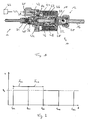
- Fig. 1 is a metering pump 10, as used for example in motor vehicles for conveying fuel to a heater, shown in longitudinal section.
- This metering pump 10 generally comprises an inlet region 12, in which liquid fuel is received, and an outlet region 14, in which the fuel delivered by the metering pump 10 is discharged.
- an inlet pipe 16 is mounted on a housing part 18. The fuel flowing through the inlet port 16 first passes through a pot screen 20 before it can enter an opening 22 in the housing part 18.
- the housing part 18 is further connected to an outer housing 24 surrounding a coil 26 on the outside.
- the coil 26 is wound on a ring-like yoke 28 and via a contact plug connection 30 in conjunction with a drive device 32nd
- outlet nozzle 34 With the outer housing 24 on the opposite side to the housing part 18 a here assembled from several parts outlet nozzle 34 is provided, in which a valve ball 36 and a valve spring 38 of an outlet check valve 40 are received.
- a passage opening 42 formed in the outlet port 34 communicates with a pump chamber 44.
- the volume of this pump chamber 44 can be varied by a pump piston 46 which can be moved back and forth in the longitudinal direction of the metering pump 10.
- the pump piston 46 together with an armature 48 carried thereon and a seal 50 which can close the opening 22, by a biasing spring 52 in the illustration of Fig. 1 biased to the right, so that the seal 50 is seated on the housing part 18 and thereby closes the opening 22.
- the pump piston 46 By applying a voltage to the coil 26 and thus energizing it by means of the control device 32, the pump piston 46 is displaced together with the armature 48 against the biasing action of the biasing spring 52 to minimize the volume of the pumping chamber 44 and thereby the fuel contained therein via the check valve 40 eject.
- the pump piston 46 moves following the biasing action of the spring 52 again in the in Fig. 1 illustrated positioning.
- the seal 50 comes into contact with the housing part 18, so that a damping function is fulfilled by the elasticity of the seal 50.
- a formed of elastic material damping plate 54 is provided in order also in the other direction of movement, ie when reaching the starting from the in Fig. 1 recognizable position shifted to the left lying movement end position to provide a damping function.
- the duration of the drive period I, a is dimensioned such that taking into account the level of the voltage U S is the desired piston displacement is obtained.
- the duration of this interval I, a in the range of 25 - are 35 ms, where the procedure can be so here is that the interval contains a certain safety period, for example, that even at relatively low ambient temperatures, the complete movement of the pump piston 46 during a obtained such interval can be.
- the excitation is then suspended during an interval I out .
- the length of this interval I from, but in principle also by setting a length of the drive period I, the operating frequency and thus the delivery rate of the metering pump 10 can be adjusted.
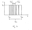
- Fig. 3 there is shown a between the switch-off time t a and t from such a drive interval I.
- This drive interval of time I a is the voltage U S applied to the coil 26, but not in a continuous but in a clocked manner.
- the voltage U S can be obtained from the vehicle electrical system or removed, it preferably being possible for a voltage U S to be applied to decouple fluctuations in the supply voltage with respect to the on-board voltage, but always to a constant level.
- the ratio of the time period or intervals I A 'to I out' determines the duty ratio of the voltage applied to the coil 26 so-called.
- This duty cycle also essentially determines the voltage applied to the coil 26 effective voltage. The greater the duty cycle, the closer the effective voltage approaches the voltage U S. The lower the duty cycle, the further the effective applied voltage decreases in comparison to the voltage U S.
- Fig. 3 recognizable aspect of the present invention can be provided in a further reduction of noises and vibrations stop on reaching a movement end position that the duty cycle previously mentioned over the duration of a drive period I, a decrease of time.
- This can be realized, for example, by the fact that, as in Fig. 3 shown, the time duration of the ON intervals I a 'is kept substantially constant while the duration of the OFF intervals of I' increases. This has the result that the frequency of the ON intervals I A 'decreases, which corresponds to a corresponding decrease in the duty ratio.
- the consequence of this reduction in the duty cycle is a decrease in the effective voltage U e as shown in FIG Fig. 4 is illustrated. This decrease in the effective voltage applied to the coil 26 voltage U e in turn leads to that in the Fig. 5 illustrated movement behavior of the pump piston 46 during a Anêtintervalls I a .
- Fig. 5 is illustrated on the vertical axis of the travel or the adjustment position of the pump piston 46, wherein with 0, for example, the in Fig. 1 illustrated state is addressed, while S max represents the other movement end state, that is, starting from the representation of the Fig. 1 maximum shifted to the left state.
- the solid curve k 1 in Fig. 5 represents the movement of the pump piston 46 when driving the coil 26 with the in Fig. 3 shown signal. It can be seen that the slope of this curve k 1 decreases as it approaches the final movement position S max , which means that the speed of the pump piston 46 decreases in a corresponding manner.
- the pulsed actuation of the metering pump 10 according to the invention for displacing the pump piston 46 in addition to avoiding impact noises and stop vibrations, further has the significant advantage that the movement of the pump piston 26 can be reproduced with significantly higher precision.
- a defined adjustable and largely uninfluenced by fluctuations in voltage U S and also prescribing the possibly over a Anêtintervall I a changing duty cycle I a '/ I off ', the movement of the pump piston 46 can be specified with high precision, which is a corresponding Precise specification or adjustment of the flow rate entails.
- Fig. 6 an alternative embodiment of a metering pump is shown.
- Components which correspond to components described above in terms of design and function are designated by the same reference numeral with the addition of an appendix "a".
- the pump piston 46a is movable in a cylinder member 60a, in which also the pump chamber 40a is provided.
- the pump piston 46a is again biased by the spring 52a, which biases the pump piston 46a in the direction of minimizing the pump chamber volume 44a. Otherwise, however, no further controllable drive arrangement is assigned to the pump piston 46a.
- a pin-shaped valve element 62a is provided in the axial extension of the pump piston 46a. This is now firmly connected to the armature 48a and is under bias of a biasing spring 64a.
- the biasing spring 64a acts on the valve element 62a such that it is biased into a movement end position in which a damping plate 66a rests on the inlet port 16a.
- the valve element 62a together with the armature 48a then in the in Fig. 6 shown positioning or movement end position against the bias of the spring 64a moves.
- an inclined groove 68a provided on the valve element 62a is positioned so as to connect the pump chamber 44a to an exhaust passage 70a, while an intake passage 72a is not connected to the pump chamber 44a.
- the duty cycle over the duration of a An horrintervalls away can be varied or reduced, for example, by increasing the frequency or by pulse width modulation to the in the valve element 62 a in Fig. 5 to obtain movement mode illustrated by the curve k 1 .
Landscapes
- Engineering & Computer Science (AREA)
- Mechanical Engineering (AREA)
- General Engineering & Computer Science (AREA)
- Physics & Mathematics (AREA)
- Fluid Mechanics (AREA)
- Electromagnetic Pumps, Or The Like (AREA)
- Reciprocating Pumps (AREA)
- Control Of Positive-Displacement Pumps (AREA)
- Lubrication Of Internal Combustion Engines (AREA)
Claims (9)
- Un système de pompe doseuse, en particulier pour une alimentation en combustible dosée d'un dispositif de chauffage d'un véhicule, comprenant une pompe doseuse (10; 10a) avec au moins un élément de pompe doseuse (46; 62a) mobile entre deux positions finales de mouvement et avec un entraînement d'élément de pompe doseuse (26, 32; 26a, 32a) associé à ce au moins un élément de pompe doseuse (46; 62a), l'entraînement d'élément de pompe doseuse (26, 32; 26a, 32a) comprenant un arrangement de bobines (26; 26a) et un dispositif d'activation (32; 32a), activant l'arrangement de bobines (26; 26a) pour produire une interaction de forces magnétiques pour avancer le au moins un élément de pompe doseuse (46; 62a) dans au moins une direction de mouvement, le dispositif d'activation (32; 32a) étant façonné pour activer l'arrangement de bobines (26; 26a) d'une manière pulsée au moins pendant certaines phases pendant un intervalle d'activation (Ion) correspondant à un processus de mouvement de l'élément de pompe doseuse,
caractérisé par un rapport impulsion/pause (Ion' / Ioff) de l'activation pulsée diminuant au moins pendant certaines phases pendant un intervalle d'activation (Ion). - Un système de pompe doseuse selon la revendication 1,
caractérisé par l'activation de l'arrangement de bobines (26; 26a) par le dispositif d'activation (32; 32a) pour produire l'interaction des forces magnétiques occasionnant l'application d'un voltage (Us) à l'arrangement de bobines (26; 26a) qui, pendant un intervalle d'activation (Ion), est pulsé, au moins pendant certaines phases. - Un système de pompe doseuse selon la revendication 1 ou 2,
caractérisé par le au moins un élément de pompe doseuse (46; 62a) étant précontraint dans une première direction de mouvement pour effectuer une procédure de mouvement et par le dispositif d'activation (32; 32a) activant l'arrangement de bobines (26; 26a) dans une deuxième direction opposée à la première direction contre la précontrainte pour effectuer une procédure de mouvement du au moins un élément de pompe doseuse (46; 62a). - Un système de pompe doseuse selon une des revendications 1 à 3,
caractérisé par une fréquence du mouvement de l'élément de pompe doseuse étant dans une gamme de 1 à 20 Hz et par une fréquence de l'activation pulsée de l'arrangement de bobines (26; 26a) étant dans une gamme de 200 à 2000 Hz. - Un système de pompe doseuse selon une des revendications 1à 4,
caractérisé par le au moins un élément de pompe doseuse (46) comprenant un piston de pompe (46) mobile pour promouvoir du fluide. - Un système de pompe doseuse selon une des revendications 1 à 5,
caractérisé par le au moins un élément de pompe doseuse (62a) comprenant un robinet-vanne (62a) mobile pour bloquer/libérer au moins un courant de fluide (70a, 72a). - Un système de pompe doseuse selon une des revendications 1à 6,
caractérisé par la durée des intervalles ON (Ion), durant lesquels pendant un intervalle d'activation (Ion) un voltage est appliqué à l'arrangement de bobines (26; 26a), étant constante pendant un intervalle d'activation (Ion) et par la durée des intervalles OFF (Ioff), durant lesquels pendant un intervalle d'activation (Ion) aucun voltage n'est appliqué à l'arrangement de bobines (26; 26a), augmentant pendant un intervalle d'activation (Ion). - Une méthode pour opérer une pompe doseuse, en particulier pour conduire du combustible à un dispositif de chauffage d'un véhicule, cette pompe doseuse (10 ; 10a) comprenant au moins un élément de pompe doseuse (46; 62a) mobile par l'excitation d'un arrangement de bobines (26; 26a) pour produire une interaction de forces magnétiques pendant un intervalle d'activation (Ion), l'arrangement de bobines (26; 26a) étant au moins par phases excité d'une manière pulsée pendant cette méthode, caractérisé par un rapport impulsion/pause (Ion' / Ioff) de l'activation pulsée de l'arrangement de bobines (26; 26a) diminuant par phases pendant un intervalle d'activation (Ion).
- Une méthode selon la revendication 8,
caractérisée par la durée des intervalles ON(Ion), durant lesquels pendant un intervalle d'activation (Ion) un voltage est appliqué à l'arrangement de bobines (26; 26a), étant constante pendant un intervalle d'activation (Ion) et par la durée des intervalles OFF (Ioff), durant lesquels pendant un intervalle d'activation (Ion) aucun voltage n'est appliqué à l'arrangement de bobines (26; 26a), augmentant pendant un intervalle d'activation (Ion).
Applications Claiming Priority (2)
| Application Number | Priority Date | Filing Date | Title |
|---|---|---|---|
| DE102004002454 | 2004-01-16 | ||
| DE102004002454A DE102004002454B4 (de) | 2004-01-16 | 2004-01-16 | Dosierpumpsystem und Verfahren zum Betreiben einer Dosierpumpe |
Publications (3)
| Publication Number | Publication Date |
|---|---|
| EP1555433A2 EP1555433A2 (fr) | 2005-07-20 |
| EP1555433A3 EP1555433A3 (fr) | 2008-12-17 |
| EP1555433B1 true EP1555433B1 (fr) | 2010-07-28 |
Family
ID=34609595
Family Applications (1)
| Application Number | Title | Priority Date | Filing Date |
|---|---|---|---|
| EP05000632A Expired - Lifetime EP1555433B1 (fr) | 2004-01-16 | 2005-01-13 | Système de dosage et procédé d'utilisation d'une pompe à dosage |
Country Status (3)
| Country | Link |
|---|---|
| EP (1) | EP1555433B1 (fr) |
| AT (1) | ATE475804T1 (fr) |
| DE (2) | DE102004002454B4 (fr) |
Families Citing this family (18)
| Publication number | Priority date | Publication date | Assignee | Title |
|---|---|---|---|---|
| DE102004051138B4 (de) * | 2004-10-20 | 2006-11-30 | Compact Dynamics Gmbh | Druckverstärkendes Brennstoff-Einspritzventil |
| DE102005024858A1 (de) * | 2005-05-31 | 2006-12-07 | J. Eberspächer GmbH & Co. KG | Verfahren zum Betreiben einer Dosierpumpe, insbesondere zum Fördern von Brennstoff für ein Fahrzeugheizgerät |
| DE102006023492A1 (de) * | 2006-05-18 | 2007-11-22 | J. Eberspächer GmbH & Co. KG | Dosierpumpe, insbesondere zum Fördern von Brennstoff für ein Fahrzeugheizgerät |
| ATE512300T1 (de) | 2006-07-12 | 2011-06-15 | Delphi Tech Holding Sarl | Dosierpumpe für eines reduktionsmittels |
| DE102008057365B4 (de) * | 2008-11-14 | 2015-12-17 | Eberspächer Climate Control Systems GmbH & Co. KG | Verfahren zum Betreiben einer elektromagnetisch betriebenen Dosierpumpe mit Anschlagdämpfung |
| DE102009019450A1 (de) * | 2009-04-29 | 2010-11-11 | Webasto Ag | Verfahren zum Betreiben und Vorrichtung mit einer Dosierpumpe |
| EP2322797B1 (fr) | 2009-11-12 | 2012-10-31 | Delphi Technologies Holding S.à.r.l. | L'armature d'un actionneur de solénoide |
| DE102010014106B4 (de) * | 2010-04-07 | 2012-03-15 | Webasto Ag | Verfahren zum Betreiben einer Dosierpumpe und Vorrichtung mit einer Dosierpumpe |
| DE102011077617A1 (de) | 2011-06-16 | 2012-12-20 | Robert Bosch Gmbh | Förderaggregat für Betriebs-/Hilfsstoffe für Verwendungskraftmaschinen |
| DE102011106932B4 (de) | 2011-07-08 | 2018-10-25 | Thomas Magnete Gmbh | Verfahren zum Betrieb eines Geräts zum Fördern und Dosieren |
| DE102011115849B3 (de) * | 2011-10-13 | 2012-05-10 | Thomas Magnete Gmbh | Vorrichtung zum Dosieren und Zerstäuben von Flüssigkeiten mit vorgespanntem Dämpfer |
| DE102011088701B4 (de) | 2011-12-15 | 2023-09-21 | Robert Bosch Gmbh | Verfahren zur Überwachung der Ankerbewegung einer Hubkolbenmagnetpumpe |
| DE102014211895A1 (de) * | 2014-06-20 | 2015-12-24 | Robert Bosch Gmbh | Verfahren und Vorrichtung zur Ansteuerung einer Hubkolbenpumpe |
| DE102014012307B3 (de) | 2014-08-19 | 2015-07-09 | Technische Universität Dresden | Verfahren zur Steuerung einer elektromagnetisch angetriebenen Hubkolbenpumpe und Vorrichtung zur Ausführung des Verfahrens |
| CN104201860A (zh) * | 2014-09-01 | 2014-12-10 | 瑞安市金星汽车泵业制造有限公司 | 一种可拆卸式电磁泵 |
| DE102016219685A1 (de) | 2016-10-11 | 2018-04-12 | Robert Bosch Gmbh | Verfahren und Vorrichtung zum Betreiben einer Rückförderpumpe |
| IT201700060837A1 (it) * | 2017-06-05 | 2018-12-05 | Ceme Spa | Motopompa idraulica elettromagnetica con pistone flottante |
| CN109340075A (zh) * | 2018-10-15 | 2019-02-15 | 安徽致信汽车科技有限公司 | 一种可以消除燃油负压空气析出的电磁泵 |
Family Cites Families (5)
| Publication number | Priority date | Publication date | Assignee | Title |
|---|---|---|---|---|
| DE2822442B1 (de) | 1978-05-23 | 1979-12-06 | Webasto Werk Baier Kg W | Dosierkolbenpumpe |
| DE10047045B4 (de) * | 2000-09-22 | 2005-10-06 | Thomas Magnete Gmbh | Elektrische Steuervorrichtung für Magnetpumpen |
| DE10103224C5 (de) * | 2001-01-25 | 2006-01-26 | J. Eberspächer GmbH & Co. KG | Dosierpumpanordnung und diese enthaltendes Dosierpumpsystem |
| DE10152782B4 (de) * | 2001-10-29 | 2005-04-07 | Webasto Ag | Verfahren zum Ansteuern einer Dosierpumpe |
| DE10158207B4 (de) * | 2001-11-28 | 2004-09-02 | Webasto Thermosysteme International Gmbh | Verfahren zum Betreiben der Dosierpumpe eines Heizgeräts mittels Dauerbestromung |
-
2004
- 2004-01-16 DE DE102004002454A patent/DE102004002454B4/de not_active Expired - Fee Related
-
2005
- 2005-01-13 AT AT05000632T patent/ATE475804T1/de not_active IP Right Cessation
- 2005-01-13 DE DE502005009989T patent/DE502005009989D1/de not_active Expired - Lifetime
- 2005-01-13 EP EP05000632A patent/EP1555433B1/fr not_active Expired - Lifetime
Also Published As
| Publication number | Publication date |
|---|---|
| DE102004002454A1 (de) | 2005-08-25 |
| EP1555433A3 (fr) | 2008-12-17 |
| EP1555433A2 (fr) | 2005-07-20 |
| DE502005009989D1 (de) | 2010-09-09 |
| ATE475804T1 (de) | 2010-08-15 |
| DE102004002454B4 (de) | 2006-06-29 |
Similar Documents
| Publication | Publication Date | Title |
|---|---|---|
| EP1555433B1 (fr) | Système de dosage et procédé d'utilisation d'une pompe à dosage | |
| EP0733799B1 (fr) | Dispositif d'injection de combustible pour moteurs à combustion interne | |
| EP0823017B1 (fr) | Procede de pilotage de la bobine d'excitation d'une pompe a piston alternatif et a commande electromagnetique | |
| EP0629264B1 (fr) | Pompe a piston alternatif | |
| DE3532549A1 (de) | Ventilsteuervorrichtung | |
| DE102007028960A1 (de) | Hochdruckpumpe für ein Kraftstoffsystem einer Brennkraftmaschine | |
| DE10247436A1 (de) | Dosierventil und Kraftstoffeinspritzpumpe | |
| DE4312414B4 (de) | Ventilanordnung für eine Bremsblockierschutz-Einrichtung | |
| DE4206817C2 (de) | Kraftstoff-Einspritzvorrichtung nach dem Festkörper-Energiespeicher-Prinzip für Brennkraftmaschinen | |
| DE102005059228A1 (de) | Elektromagnetische Betätigungsvorrichtung für ein Kraftstoffeinspritzventil | |
| EP3066343A1 (fr) | Pompe magnétique pour groupe auxiliaire de véhicule ainsi que procédé de commande d'une pompe magnétique pour groupe auxiliaire | |
| EP0309501B1 (fr) | Pompe d'Injection à Combustible pour des Moteurs à Combustion Interne | |
| DE2946671C2 (fr) | ||
| EP1729008B1 (fr) | Procédé pour opérer une pompe à dosage, en particulier pour pomper un combustible d'un chauffage de vehicule | |
| DE10301093A1 (de) | Dosierpumpeinrichtung für ein Fahrzeugheizgerät | |
| EP1155233A1 (fr) | Mecanisme de regulation permettant de commander une augmentation de pression de carburant, destine a un injecteur de carburant | |
| EP0651858B1 (fr) | Pompe a entrainement electromagnetique | |
| DE10149412C1 (de) | Vorrichtung zum Dämpfen von Druckpulsationen in einem Fluidsystem, insbesondere in einem Kraftstoffsystem einer Brennkraftmaschine, sowie Verfahren zum Betreiben einer Brennkraftmaschine | |
| DE102018120950B4 (de) | Dosierpumpe | |
| DE10230267A1 (de) | Verfahren zur Ansteuerung einer Fluid-Dosiervorrichtung und Common-Rail-Injektor | |
| EP1861617B1 (fr) | Dispositif d'injection de carburant | |
| DE69812749T2 (de) | Spritzverstelleinrichtung für Hochdruck-Kraftstoffpumpe | |
| DE102009023007A1 (de) | Mikrodosierpumpe und Verfahren hierfür | |
| DE10249559B4 (de) | Regelorgan | |
| DE102009033736A1 (de) | Förder- oder Dosierpumpe, und Verfahren zu deren Betrieb |
Legal Events
| Date | Code | Title | Description |
|---|---|---|---|
| PUAI | Public reference made under article 153(3) epc to a published international application that has entered the european phase |
Free format text: ORIGINAL CODE: 0009012 |
|
| AK | Designated contracting states |
Kind code of ref document: A2 Designated state(s): AT BE BG CH CY CZ DE DK EE ES FI FR GB GR HU IE IS IT LI LT LU MC NL PL PT RO SE SI SK TR |
|
| AX | Request for extension of the european patent |
Extension state: AL BA HR LV MK YU |
|
| PUAL | Search report despatched |
Free format text: ORIGINAL CODE: 0009013 |
|
| AK | Designated contracting states |
Kind code of ref document: A3 Designated state(s): AT BE BG CH CY CZ DE DK EE ES FI FR GB GR HU IE IS IT LI LT LU MC NL PL PT RO SE SI SK TR |
|
| AX | Request for extension of the european patent |
Extension state: AL BA HR LV MK YU |
|
| 17P | Request for examination filed |
Effective date: 20090617 |
|
| AKX | Designation fees paid |
Designated state(s): AT CZ DE FR PL SE |
|
| 17Q | First examination report despatched |
Effective date: 20090904 |
|
| GRAP | Despatch of communication of intention to grant a patent |
Free format text: ORIGINAL CODE: EPIDOSNIGR1 |
|
| GRAS | Grant fee paid |
Free format text: ORIGINAL CODE: EPIDOSNIGR3 |
|
| GRAA | (expected) grant |
Free format text: ORIGINAL CODE: 0009210 |
|
| AK | Designated contracting states |
Kind code of ref document: B1 Designated state(s): AT CZ DE FR PL SE |
|
| REF | Corresponds to: |
Ref document number: 502005009989 Country of ref document: DE Date of ref document: 20100909 Kind code of ref document: P |
|
| REG | Reference to a national code |
Ref country code: SE Ref legal event code: TRGR |
|
| PG25 | Lapsed in a contracting state [announced via postgrant information from national office to epo] |
Ref country code: PL Free format text: LAPSE BECAUSE OF FAILURE TO SUBMIT A TRANSLATION OF THE DESCRIPTION OR TO PAY THE FEE WITHIN THE PRESCRIBED TIME-LIMIT Effective date: 20100728 |
|
| PG25 | Lapsed in a contracting state [announced via postgrant information from national office to epo] |
Ref country code: CZ Free format text: LAPSE BECAUSE OF FAILURE TO SUBMIT A TRANSLATION OF THE DESCRIPTION OR TO PAY THE FEE WITHIN THE PRESCRIBED TIME-LIMIT Effective date: 20100728 |
|
| PLBE | No opposition filed within time limit |
Free format text: ORIGINAL CODE: 0009261 |
|
| STAA | Information on the status of an ep patent application or granted ep patent |
Free format text: STATUS: NO OPPOSITION FILED WITHIN TIME LIMIT |
|
| 26N | No opposition filed |
Effective date: 20110429 |
|
| REG | Reference to a national code |
Ref country code: DE Ref legal event code: R097 Ref document number: 502005009989 Country of ref document: DE Effective date: 20110429 |
|
| REG | Reference to a national code |
Ref country code: SE Ref legal event code: EUG |
|
| REG | Reference to a national code |
Ref country code: FR Ref legal event code: ST Effective date: 20110930 |
|
| PG25 | Lapsed in a contracting state [announced via postgrant information from national office to epo] |
Ref country code: FR Free format text: LAPSE BECAUSE OF NON-PAYMENT OF DUE FEES Effective date: 20110131 |
|
| REG | Reference to a national code |
Ref country code: AT Ref legal event code: MM01 Ref document number: 475804 Country of ref document: AT Kind code of ref document: T Effective date: 20110113 |
|
| PG25 | Lapsed in a contracting state [announced via postgrant information from national office to epo] |
Ref country code: AT Free format text: LAPSE BECAUSE OF NON-PAYMENT OF DUE FEES Effective date: 20110113 |
|
| PG25 | Lapsed in a contracting state [announced via postgrant information from national office to epo] |
Ref country code: SE Free format text: LAPSE BECAUSE OF NON-PAYMENT OF DUE FEES Effective date: 20110114 |
|
| REG | Reference to a national code |
Ref country code: DE Ref legal event code: R082 Ref document number: 502005009989 Country of ref document: DE Representative=s name: WEICKMANN & WEICKMANN, DE |
|
| REG | Reference to a national code |
Ref country code: DE Ref legal event code: R081 Ref document number: 502005009989 Country of ref document: DE Owner name: EBERSPAECHER CLIMATE CONTROL SYSTEMS GMBH & CO, DE Free format text: FORMER OWNER: J. EBERSPAECHER GMBH & CO. KG, 73730 ESSLINGEN, DE Effective date: 20130607 Ref country code: DE Ref legal event code: R082 Ref document number: 502005009989 Country of ref document: DE Representative=s name: WEICKMANN & WEICKMANN, DE Effective date: 20130607 Ref country code: DE Ref legal event code: R082 Ref document number: 502005009989 Country of ref document: DE Representative=s name: RUTTENSPERGER LACHNIT TROSSIN GOMOLL PATENT- U, DE Effective date: 20130607 Ref country code: DE Ref legal event code: R082 Ref document number: 502005009989 Country of ref document: DE Representative=s name: RUTTENSPERGER LACHNIT TROSSIN GOMOLL, PATENT- , DE Effective date: 20130607 |
|
| REG | Reference to a national code |
Ref country code: DE Ref legal event code: R082 Ref document number: 502005009989 Country of ref document: DE Representative=s name: RUTTENSPERGER LACHNIT TROSSIN GOMOLL PATENT- U, DE Ref country code: DE Ref legal event code: R082 Ref document number: 502005009989 Country of ref document: DE Representative=s name: RUTTENSPERGER LACHNIT TROSSIN GOMOLL, PATENT- , DE |
|
| PGFP | Annual fee paid to national office [announced via postgrant information from national office to epo] |
Ref country code: DE Payment date: 20160131 Year of fee payment: 12 |
|
| REG | Reference to a national code |
Ref country code: DE Ref legal event code: R119 Ref document number: 502005009989 Country of ref document: DE |
|
| PG25 | Lapsed in a contracting state [announced via postgrant information from national office to epo] |
Ref country code: DE Free format text: LAPSE BECAUSE OF NON-PAYMENT OF DUE FEES Effective date: 20170801 |