EP0823017B1 - Procede de pilotage de la bobine d'excitation d'une pompe a piston alternatif et a commande electromagnetique - Google Patents
Procede de pilotage de la bobine d'excitation d'une pompe a piston alternatif et a commande electromagnetique Download PDFInfo
- Publication number
- EP0823017B1 EP0823017B1 EP96914114A EP96914114A EP0823017B1 EP 0823017 B1 EP0823017 B1 EP 0823017B1 EP 96914114 A EP96914114 A EP 96914114A EP 96914114 A EP96914114 A EP 96914114A EP 0823017 B1 EP0823017 B1 EP 0823017B1
- Authority
- EP
- European Patent Office
- Prior art keywords
- current
- pulse
- energizing
- energizing coil
- control circuit
- Prior art date
- Legal status (The legal status is an assumption and is not a legal conclusion. Google has not performed a legal analysis and makes no representation as to the accuracy of the status listed.)
- Expired - Lifetime
Links
- 238000000034 method Methods 0.000 title claims abstract description 31
- 239000000446 fuel Substances 0.000 claims abstract description 42
- 238000002347 injection Methods 0.000 claims abstract description 33
- 239000007924 injection Substances 0.000 claims abstract description 33
- 230000000630 rising effect Effects 0.000 claims abstract description 19
- 239000003990 capacitor Substances 0.000 claims description 16
- 238000004146 energy storage Methods 0.000 claims description 3
- 230000001174 ascending effect Effects 0.000 claims 3
- 230000006698 induction Effects 0.000 abstract description 4
- 230000011664 signaling Effects 0.000 abstract 1
- 230000005284 excitation Effects 0.000 description 57
- 239000012528 membrane Substances 0.000 description 8
- 238000010586 diagram Methods 0.000 description 5
- 238000006073 displacement reaction Methods 0.000 description 4
- 239000007788 liquid Substances 0.000 description 3
- 230000001133 acceleration Effects 0.000 description 2
- 238000002485 combustion reaction Methods 0.000 description 2
- 230000006835 compression Effects 0.000 description 2
- 238000007906 compression Methods 0.000 description 2
- 238000010438 heat treatment Methods 0.000 description 2
- 238000004519 manufacturing process Methods 0.000 description 2
- 230000006978 adaptation Effects 0.000 description 1
- 238000004891 communication Methods 0.000 description 1
- 230000001419 dependent effect Effects 0.000 description 1
- 238000011161 development Methods 0.000 description 1
- 230000018109 developmental process Effects 0.000 description 1
- 230000005611 electricity Effects 0.000 description 1
- 238000009415 formwork Methods 0.000 description 1
- 238000007654 immersion Methods 0.000 description 1
- 210000000056 organ Anatomy 0.000 description 1
- 238000005507 spraying Methods 0.000 description 1
Images





Classifications
-
- F—MECHANICAL ENGINEERING; LIGHTING; HEATING; WEAPONS; BLASTING
- F02—COMBUSTION ENGINES; HOT-GAS OR COMBUSTION-PRODUCT ENGINE PLANTS
- F02D—CONTROLLING COMBUSTION ENGINES
- F02D41/00—Electrical control of supply of combustible mixture or its constituents
- F02D41/20—Output circuits, e.g. for controlling currents in command coils
-
- H—ELECTRICITY
- H01—ELECTRIC ELEMENTS
- H01F—MAGNETS; INDUCTANCES; TRANSFORMERS; SELECTION OF MATERIALS FOR THEIR MAGNETIC PROPERTIES
- H01F7/00—Magnets
- H01F7/06—Electromagnets; Actuators including electromagnets
- H01F7/08—Electromagnets; Actuators including electromagnets with armatures
- H01F7/18—Circuit arrangements for obtaining desired operating characteristics, e.g. for slow operation, for sequential energisation of windings, for high-speed energisation of windings
-
- F—MECHANICAL ENGINEERING; LIGHTING; HEATING; WEAPONS; BLASTING
- F02—COMBUSTION ENGINES; HOT-GAS OR COMBUSTION-PRODUCT ENGINE PLANTS
- F02D—CONTROLLING COMBUSTION ENGINES
- F02D41/00—Electrical control of supply of combustible mixture or its constituents
- F02D41/20—Output circuits, e.g. for controlling currents in command coils
- F02D2041/2003—Output circuits, e.g. for controlling currents in command coils using means for creating a boost voltage, i.e. generation or use of a voltage higher than the battery voltage, e.g. to speed up injector opening
- F02D2041/2006—Output circuits, e.g. for controlling currents in command coils using means for creating a boost voltage, i.e. generation or use of a voltage higher than the battery voltage, e.g. to speed up injector opening by using a boost capacitor
-
- F—MECHANICAL ENGINEERING; LIGHTING; HEATING; WEAPONS; BLASTING
- F02—COMBUSTION ENGINES; HOT-GAS OR COMBUSTION-PRODUCT ENGINE PLANTS
- F02D—CONTROLLING COMBUSTION ENGINES
- F02D41/00—Electrical control of supply of combustible mixture or its constituents
- F02D41/20—Output circuits, e.g. for controlling currents in command coils
- F02D2041/202—Output circuits, e.g. for controlling currents in command coils characterised by the control of the circuit
- F02D2041/2024—Output circuits, e.g. for controlling currents in command coils characterised by the control of the circuit the control switching a load after time-on and time-off pulses
- F02D2041/2027—Control of the current by pulse width modulation or duty cycle control
-
- F—MECHANICAL ENGINEERING; LIGHTING; HEATING; WEAPONS; BLASTING
- F02—COMBUSTION ENGINES; HOT-GAS OR COMBUSTION-PRODUCT ENGINE PLANTS
- F02D—CONTROLLING COMBUSTION ENGINES
- F02D41/00—Electrical control of supply of combustible mixture or its constituents
- F02D41/20—Output circuits, e.g. for controlling currents in command coils
- F02D2041/202—Output circuits, e.g. for controlling currents in command coils characterised by the control of the circuit
- F02D2041/2034—Control of the current gradient
-
- F—MECHANICAL ENGINEERING; LIGHTING; HEATING; WEAPONS; BLASTING
- F02—COMBUSTION ENGINES; HOT-GAS OR COMBUSTION-PRODUCT ENGINE PLANTS
- F02D—CONTROLLING COMBUSTION ENGINES
- F02D41/00—Electrical control of supply of combustible mixture or its constituents
- F02D41/20—Output circuits, e.g. for controlling currents in command coils
- F02D2041/202—Output circuits, e.g. for controlling currents in command coils characterised by the control of the circuit
- F02D2041/2058—Output circuits, e.g. for controlling currents in command coils characterised by the control of the circuit using information of the actual current value
Definitions
- Electromagnetically driven reciprocating pump is out of the WO-A-93 18290 known.
- This method uses a current control circuit used depending on a current setpoint in the form of a preset current or a preset voltage excitation current flowing through the excitation coil 600 (FIG. 1) controls.
- the excitation coil 600 is connected to a power transistor 601 connected via a measuring resistor 602 to ground is present, at the control input of transistor 601, for example to the transistor base, a comparator 603 with its Output is created.
- the non-inverting input of the Comparator 603 is acted upon by the current setpoint that for example by means of a microcomputer.
- each pulse of the current setpoint is assigned a gradually rising rising edge driven, one correspondingly gradually rising rising edge at the pulse of the Excitation current in the excitation coil causes, the excitation current does not change faster than that due to the mutual induction limited maximum current change in the excitation coil allows the at the minimum available voltage is possible.
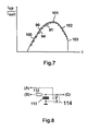
- the method according to the invention thus becomes a current setpoint Curve 90 predefined at the input of the current control circuit, which causes a corresponding excitation current 91 in the excitation coil (Fig. 6).
- the course of the current setpoint curve 90 becomes like this chosen so that the excitation current 91 obtained here is always in the control range the current control circuit, i.e. the slope of the Current setpoint curve 90 smaller than the maximum current change at the minimum available at the excitation coil Tension is. As stated above, this tension can be dependent vary greatly in temperature and engine load.
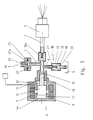
- the armature 10 is in the de-energized state of the coil 9 Pump 1 by the bias of the spring 12 on the bottom 11a.
- the Fuel feed valve 16 is closed and the storage membrane 23 is by the spring 24 in its by the Abutment surface 22a held in the withdrawn position in the housing cavity.
- the coil 9 is switched off. Of the Armature 10 is moved back to floor 11a by spring 12. The amount of liquid stored in the storage device 6 via lines 7 and 2 in the feed cylinder 15 sucked back, and the membrane 23 as a result of the action of Spring 24 pushed back into its original position. At the same time opens the fuel supply valve 16 so that fuel from the Tank 5 is sucked up.
- the excitation or coil current i sp through the excitation coil 9 causes a stroke s of the armature 10 or the delivery piston 14, which is offset in time with respect to the onset of the excitation current.
- the pressure build-up of the injection pressure p takes place with a time offset with respect to the stroke s, namely only when the displacement of the fuel is suddenly stopped and the fuel is suddenly compressed due to the already high kinetic energy of the delivery piston 14 (FIG. 4).
- the corresponding adaptation which is generally carried out by reference voltage 111 (U 0 ), does not have to be readjusted permanently, but can, for example, be adapted to the changed motor states at time intervals which correspond to one motor revolution. This means a considerable relief for the control device to be used.
Landscapes
- Engineering & Computer Science (AREA)
- Physics & Mathematics (AREA)
- Electromagnetism (AREA)
- Power Engineering (AREA)
- Mechanical Engineering (AREA)
- Combustion & Propulsion (AREA)
- Chemical & Material Sciences (AREA)
- General Engineering & Computer Science (AREA)
- Fuel-Injection Apparatus (AREA)
- Electromagnetic Pumps, Or The Like (AREA)
- Electrical Control Of Air Or Fuel Supplied To Internal-Combustion Engine (AREA)
- Reciprocating, Oscillating Or Vibrating Motors (AREA)
- Control Of Positive-Displacement Pumps (AREA)
Claims (9)
- Procédé de commande d'une bobine d'excitation d'une pompe à piston alternatif à entraínement magnétique utilisée comme dispositif d'injection de carburant, dans lequel la bobine d'excitation est excitée par un courant d'excitation en forme d'impulsions à haute fréquence par l'intermédiaire d'un circuit de commande du courant, et chaque impulsion produit un a-coup de déplacement d'un induit entraíné par la bobine d'excitation, et le circuit de commande du courant commande le courant d'excitation passant dans la bobine d'excitation en fonction d'une courbe de la valeur de consigne du courant,
caractérisé en ce que
chaque impulsion de la courbe de la valeur de consigne du courant présente un flanc montant, progressivement croissant qui produit un flanc montant, progressivement croissant, correspondant, de l'impulsion de courant d'excitation dans la bobine d'excitation, la courbe de la valeur de consigne du courant étant commandée de telle sorte que le courant d'excitation ne varie pas plus rapidement que la modification maximale du courant, limitée à cause de la contre-induction, qui est possible à la tension minimale disponible sur la bobine d'excitation. - Procédé selon la revendication 1, caractérisé en ce que le flanc montant, progressivement croissant de la courbe de la valeur de consigne du courant est commandé pour évoluer à la manière d'une fonction exponentielle.
- Procédé selon la revendication 1 ou 2, caractérisé en ce que l'on détecte une vitesse de rotation du moteur et/ou une température régnant dans la bobine d'excitation pour adapter la courbe de la valeur de consigne du courant à la tension disponible sur la bobine d'excitation.
- Procédé selon l'une des revendications 1 à 3, caractérisé en ce que la courbe de la valeur de consigne du courant est calculée par un microprocesseur et est par exemple appliquée au circuit de commande du courant à l'aide d'un convertisseur numérique/analogique.
- Procédé selon l'une des revendications 1 à 4, caractérisé en ce que chaque impulsion de la courbe de la valeur de consigne du courant correspond à une fonction exponentielle sur l'ensemble de son évolution.
- Procédé selon l'une des revendications 1 à 5, caractérisé en ce que la courbe de la valeur de consigne du courant est adaptée à une géométrie spéciale de la pompe à piston alternatif, en particulier à une dépendance de la force (F) vis-à-vis de l'interstice d'air de travail (1), et présente par exemple une forme en cloche.
- Procédé selon l'une des revendications 1 à 6, caractérisé en ce que l'évolution de la courbe de la valeur de consigne du courant est produite au moyen d'un circuit de commande de la valeur de consigne, dans lequel le circuit de commande de la valeur de consigne présente un élément RC doté d'une résistance (112) et d'un condensateur (113), le condensateur (113) est chargé à travers la résistance (112) à des intervalles de temps réguliers, et produit ainsi une courbe de la valeur de consigne du courant en forme d'impulsion correspondant à une fonction exponentielle.
- Procédé selon l'une des revendications 1 à 7, caractérisé en ce que la longueur des impulsions et l'évolution de la montée des impulsions de la courbe de la valeur de consigne du courant sont commandées de manière mutuellement indépendante, en appliquant un signal (111) en impulsions rectangulaires à un commutateur (114) qui court-circuite le condensateur (113), et en appliquant une tension de référence (111) au condensateur (113) à travers la résistance (112), dont la valeur peut être modifiée.
- Procédé selon l'une des revendications i à 8, caractérisé en ce que l'on utilise comme dispositif d'injection de carburant un dispositif d'injection de carburant PDS travaillant suivant le principe de l'accumulateur à corps solide.
Applications Claiming Priority (3)
| Application Number | Priority Date | Filing Date | Title |
|---|---|---|---|
| DE19515775 | 1995-04-28 | ||
| DE19515775A DE19515775C2 (de) | 1995-04-28 | 1995-04-28 | Verfahren zum Ansteuern einer Erregerspule einer elektromagnetisch angetriebenen Hubkolbenpumpe |
| PCT/EP1996/001716 WO1996034192A1 (fr) | 1995-04-28 | 1996-04-24 | Procede de pilotage de la bobine d'excitation d'une pompe a piston alternatif et a commande electromagnetique |
Publications (2)
| Publication Number | Publication Date |
|---|---|
| EP0823017A1 EP0823017A1 (fr) | 1998-02-11 |
| EP0823017B1 true EP0823017B1 (fr) | 1999-08-11 |
Family
ID=7760677
Family Applications (1)
| Application Number | Title | Priority Date | Filing Date |
|---|---|---|---|
| EP96914114A Expired - Lifetime EP0823017B1 (fr) | 1995-04-28 | 1996-04-24 | Procede de pilotage de la bobine d'excitation d'une pompe a piston alternatif et a commande electromagnetique |
Country Status (10)
| Country | Link |
|---|---|
| US (1) | US6024071A (fr) |
| EP (1) | EP0823017B1 (fr) |
| JP (1) | JP3264375B2 (fr) |
| KR (1) | KR19990008091A (fr) |
| AT (1) | ATE183283T1 (fr) |
| AU (1) | AU692103B2 (fr) |
| CA (1) | CA2217532A1 (fr) |
| DE (2) | DE19515775C2 (fr) |
| ES (1) | ES2136405T3 (fr) |
| WO (1) | WO1996034192A1 (fr) |
Families Citing this family (26)
| Publication number | Priority date | Publication date | Assignee | Title |
|---|---|---|---|---|
| FR2803139B1 (fr) * | 1999-12-23 | 2007-12-21 | Delachaux Sa | Generateur de signal electrique a frequence variable, asservissement et moyens de calcul de faible cout |
| US7111460B2 (en) * | 2000-03-02 | 2006-09-26 | New Power Concepts Llc | Metering fuel pump |
| US6966760B1 (en) | 2000-03-17 | 2005-11-22 | Brp Us Inc. | Reciprocating fluid pump employing reversing polarity motor |
| WO2002012708A1 (fr) * | 2000-08-02 | 2002-02-14 | Mikuni Corporation | Injecteur de carburant a commande electronique |
| US6621269B2 (en) * | 2001-04-11 | 2003-09-16 | Daimlerchrysler Corporation | System for monitoring solenoid flyback voltage spike |
| KR20040063157A (ko) * | 2001-11-29 | 2004-07-12 | 가부시키가이샤 미쿠니 | 연료분사펌프의 구동방법 |
| US6757149B2 (en) * | 2002-03-04 | 2004-06-29 | Visteon Global Technologies, Inc. | Method for controlling fuel injector valve solenoid current |
| US8511105B2 (en) | 2002-11-13 | 2013-08-20 | Deka Products Limited Partnership | Water vending apparatus |
| US8069676B2 (en) | 2002-11-13 | 2011-12-06 | Deka Products Limited Partnership | Water vapor distillation apparatus, method and system |
| US7340879B2 (en) * | 2002-11-13 | 2008-03-11 | Deka Products Limited Partnership | Locally powered water distillation system |
| FI115008B (fi) * | 2003-05-13 | 2005-02-15 | Waertsilae Finland Oy | Menetelmä solenoidin toiminnan valvomiseksi |
| US7753657B2 (en) * | 2005-02-02 | 2010-07-13 | Brp Us Inc. | Method of controlling a pumping assembly |
| US11826681B2 (en) | 2006-06-30 | 2023-11-28 | Deka Products Limited Partneship | Water vapor distillation apparatus, method and system |
| US11884555B2 (en) | 2007-06-07 | 2024-01-30 | Deka Products Limited Partnership | Water vapor distillation apparatus, method and system |
| US8006511B2 (en) | 2007-06-07 | 2011-08-30 | Deka Products Limited Partnership | Water vapor distillation apparatus, method and system |
| US8359877B2 (en) * | 2008-08-15 | 2013-01-29 | Deka Products Limited Partnership | Water vending apparatus |
| CN102297065B (zh) * | 2011-08-30 | 2013-04-17 | 潍柴动力股份有限公司 | 具有关闭时间偏差补偿的喷油器 |
| WO2014018896A1 (fr) | 2012-07-27 | 2014-01-30 | Deka Products Limited Partnership | Commande de la conductivité dans une sortie d'eau de production destinée à un évaporateur |
| US9500170B2 (en) | 2012-10-25 | 2016-11-22 | Picospray, Llc | Fuel injection system |
| DE102014203364B4 (de) * | 2014-02-25 | 2023-03-23 | Vitesco Technologies GmbH | Verfahren und Vorrichtung zum Betrieb eines Ventils, insbesondere für ein Speichereinspritzsystem |
| CN109312735A (zh) | 2016-05-12 | 2019-02-05 | 布里格斯斯特拉顿公司 | 燃料输送喷射器 |
| US10947940B2 (en) * | 2017-03-28 | 2021-03-16 | Briggs & Stratton, Llc | Fuel delivery system |
| US10920768B2 (en) * | 2017-09-14 | 2021-02-16 | Milton Roy, Llc | Pump drive that minimizes a pulse width based on voltage data to improve intake and discharge strokes |
| US11698064B2 (en) * | 2017-12-29 | 2023-07-11 | Koninklijke Philips N.V. | System and method for operating a pump in a humidifier |
| US10443530B1 (en) * | 2018-05-22 | 2019-10-15 | Gm Global Technology Operations Llc. | System with solenoid assembly and method of fault diagnosis and isolation |
| US11668270B2 (en) | 2018-10-12 | 2023-06-06 | Briggs & Stratton, Llc | Electronic fuel injection module |
Family Cites Families (14)
| Publication number | Priority date | Publication date | Assignee | Title |
|---|---|---|---|---|
| FR2370216A1 (fr) * | 1976-11-05 | 1978-06-02 | Renault | Dispositif de commande par programme de courant de plusieurs electrovannes a fonctionnement asynchrone simultane ou non |
| DE2841781A1 (de) * | 1978-09-26 | 1980-04-10 | Bosch Gmbh Robert | Einrichtung zum betrieb von elektromagnetischen verbrauchern bei brennkraftmaschinen |
| US4238813A (en) * | 1979-05-21 | 1980-12-09 | The Bendix Corporation | Compensated dual injector driver |
| US4408129A (en) * | 1981-06-18 | 1983-10-04 | International Business Machines Corporation | Constant energy drive circuit for electromagnetic print hammers |
| DE3139987A1 (de) * | 1981-10-08 | 1983-04-28 | Robert Bosch Gmbh, 7000 Stuttgart | Steuereinrichtung fuer einen elektromagnetischen verbraucher in einem kraftfahrzeug, insbesondere ein magnetventil oder ein stellmagnet |
| JPS59103091A (ja) * | 1982-12-01 | 1984-06-14 | Nippon Denso Co Ltd | 電磁弁の通電電流制御方法 |
| US4729056A (en) * | 1986-10-02 | 1988-03-01 | Motorola, Inc. | Solenoid driver control circuit with initial boost voltage |
| DE3722527A1 (de) * | 1987-07-08 | 1989-01-19 | Vdo Schindling | Verfahren und schaltungsanordnung zur ansteuerung eines einspritzventils |
| US4980793A (en) * | 1988-04-29 | 1990-12-25 | Chrysler Corporation | Open loop control of solenoid coil driver |
| DE3923487A1 (de) * | 1989-07-15 | 1991-01-24 | Fev Motorentech Gmbh & Co Kg | Verfahren zum ansteuern von stellgliedern |
| JP2780244B2 (ja) * | 1989-11-17 | 1998-07-30 | 株式会社日立製作所 | アイドル制御弁の駆動制御方法及び装置 |
| DE4206817C2 (de) * | 1991-10-07 | 1994-02-24 | Ficht Gmbh | Kraftstoff-Einspritzvorrichtung nach dem Festkörper-Energiespeicher-Prinzip für Brennkraftmaschinen |
| AU664739B2 (en) * | 1992-03-04 | 1995-11-30 | Ficht Gmbh & Co. Kg | Circuit for controlling an exciting coil of an electromagnetically driven reciprocating piston pump |
| US5381297A (en) * | 1993-06-18 | 1995-01-10 | Siemens Automotive L.P. | System and method for operating high speed solenoid actuated devices |
-
1995
- 1995-04-28 DE DE19515775A patent/DE19515775C2/de not_active Expired - Fee Related
-
1996
- 1996-04-24 JP JP53216796A patent/JP3264375B2/ja not_active Expired - Fee Related
- 1996-04-24 DE DE59602721T patent/DE59602721D1/de not_active Expired - Fee Related
- 1996-04-24 WO PCT/EP1996/001716 patent/WO1996034192A1/fr not_active Ceased
- 1996-04-24 KR KR1019970707615A patent/KR19990008091A/ko not_active Abandoned
- 1996-04-24 ES ES96914114T patent/ES2136405T3/es not_active Expired - Lifetime
- 1996-04-24 AU AU57610/96A patent/AU692103B2/en not_active Withdrawn - After Issue
- 1996-04-24 US US08/945,706 patent/US6024071A/en not_active Expired - Lifetime
- 1996-04-24 AT AT96914114T patent/ATE183283T1/de not_active IP Right Cessation
- 1996-04-24 CA CA002217532A patent/CA2217532A1/fr not_active Abandoned
- 1996-04-24 EP EP96914114A patent/EP0823017B1/fr not_active Expired - Lifetime
Also Published As
| Publication number | Publication date |
|---|---|
| ES2136405T3 (es) | 1999-11-16 |
| DE19515775A1 (de) | 1996-10-31 |
| JP3264375B2 (ja) | 2002-03-11 |
| AU5761096A (en) | 1996-11-18 |
| DE59602721D1 (de) | 1999-09-16 |
| JPH11505307A (ja) | 1999-05-18 |
| WO1996034192A1 (fr) | 1996-10-31 |
| AU692103B2 (en) | 1998-05-28 |
| KR19990008091A (ko) | 1999-01-25 |
| ATE183283T1 (de) | 1999-08-15 |
| US6024071A (en) | 2000-02-15 |
| DE19515775C2 (de) | 1998-08-06 |
| EP0823017A1 (fr) | 1998-02-11 |
| CA2217532A1 (fr) | 1996-10-31 |
Similar Documents
| Publication | Publication Date | Title |
|---|---|---|
| DE19515775C2 (de) | Verfahren zum Ansteuern einer Erregerspule einer elektromagnetisch angetriebenen Hubkolbenpumpe | |
| EP0629264B1 (fr) | Pompe a piston alternatif | |
| EP0733799B1 (fr) | Dispositif d'injection de combustible pour moteurs à combustion interne | |
| EP0241697B1 (fr) | Dispositif d'injection du combustible pour moteurs à combustion interne | |
| DE3700687C2 (de) | Kraftstoffeinspritzanlage für eine Brennkraftmaschine | |
| EP1305520B1 (fr) | Procede pour commander une soupape d'injection | |
| WO2005103469A9 (fr) | Procede permettant d'entrainer une vanne magnetique pour une commande de quantite | |
| EP1555433B1 (fr) | Système de dosage et procédé d'utilisation d'une pompe à dosage | |
| DD147387A5 (de) | Elektronisch geregelte einspritzanlage mit pumpe-duesen-einrichtung | |
| DE4206817A1 (de) | Kraftstoff-einspritzvorrichtung nach dem festkoerper-energiespeicher-prinzip fuer brennkraftmaschinen | |
| DE2946671C2 (fr) | ||
| EP0309501B1 (fr) | Pompe d'Injection à Combustible pour des Moteurs à Combustion Interne | |
| DE3601710C2 (de) | Kraftstoffeinspritzvorrichtung für Brennkraftmaschinen | |
| DE4018320C2 (de) | Ansteuerschaltung für einen elektromagnetischen Verbraucher | |
| WO2013174604A1 (fr) | Procédé de fonctionnement d'un système de carburant de moteur à combustion interne | |
| WO2004005687A1 (fr) | Procede d'amorcage d'un dispositif de dosage de fluide et injecteur common rail | |
| DE102005046933B4 (de) | Verfahren zum Ansteuern eines piezobetätigten Einspritzventils | |
| DE10051343B4 (de) | Verfahren zum Einspritzen von Kraftstoff mit Mehrfachansteuerung eines Steuerventiles | |
| EP0927821B1 (fr) | Procédé de commande d' un système d' injection de carburant | |
| EP0834009A1 (fr) | Systeme commandant le dosage du carburant dans un moteur a combustion interne | |
| DE102009023007A1 (de) | Mikrodosierpumpe und Verfahren hierfür | |
| WO2001034957A2 (fr) | Commande assistee par accumulateur d'energie des quantites d'injection dans des moteurs diesel importants | |
| WO2002008598A1 (fr) | Procede de commande d'une soupape d'injection destinee a l'injection de carburant dans un moteur thermique | |
| DE102004003417A1 (de) | Verfahren und Vorrichtung zur Steuerung einer Brennkraftmaschine | |
| DE10059399A1 (de) | Vorrichtung zur Verbesserung der Einspritzabfolge bei Kraftstoffeinspritzsystemen |
Legal Events
| Date | Code | Title | Description |
|---|---|---|---|
| PUAI | Public reference made under article 153(3) epc to a published international application that has entered the european phase |
Free format text: ORIGINAL CODE: 0009012 |
|
| 17P | Request for examination filed |
Effective date: 19971027 |
|
| AK | Designated contracting states |
Kind code of ref document: A1 Designated state(s): AT BE DE ES FR GB IT SE |
|
| GRAG | Despatch of communication of intention to grant |
Free format text: ORIGINAL CODE: EPIDOS AGRA |
|
| 17Q | First examination report despatched |
Effective date: 19981207 |
|
| GRAG | Despatch of communication of intention to grant |
Free format text: ORIGINAL CODE: EPIDOS AGRA |
|
| GRAH | Despatch of communication of intention to grant a patent |
Free format text: ORIGINAL CODE: EPIDOS IGRA |
|
| GRAH | Despatch of communication of intention to grant a patent |
Free format text: ORIGINAL CODE: EPIDOS IGRA |
|
| GRAA | (expected) grant |
Free format text: ORIGINAL CODE: 0009210 |
|
| AK | Designated contracting states |
Kind code of ref document: B1 Designated state(s): AT BE DE ES FR GB IT SE |
|
| REF | Corresponds to: |
Ref document number: 183283 Country of ref document: AT Date of ref document: 19990815 Kind code of ref document: T |
|
| GBT | Gb: translation of ep patent filed (gb section 77(6)(a)/1977) |
Effective date: 19990812 |
|
| ITF | It: translation for a ep patent filed | ||
| REF | Corresponds to: |
Ref document number: 59602721 Country of ref document: DE Date of ref document: 19990916 |
|
| ET | Fr: translation filed | ||
| REG | Reference to a national code |
Ref country code: ES Ref legal event code: FG2A Ref document number: 2136405 Country of ref document: ES Kind code of ref document: T3 |
|
| PG25 | Lapsed in a contracting state [announced via postgrant information from national office to epo] |
Ref country code: AT Free format text: LAPSE BECAUSE OF NON-PAYMENT OF DUE FEES Effective date: 20000424 |
|
| PG25 | Lapsed in a contracting state [announced via postgrant information from national office to epo] |
Ref country code: ES Free format text: LAPSE BECAUSE OF NON-PAYMENT OF DUE FEES Effective date: 20000425 |
|
| PLBE | No opposition filed within time limit |
Free format text: ORIGINAL CODE: 0009261 |
|
| STAA | Information on the status of an ep patent application or granted ep patent |
Free format text: STATUS: NO OPPOSITION FILED WITHIN TIME LIMIT |
|
| 26N | No opposition filed | ||
| REG | Reference to a national code |
Ref country code: GB Ref legal event code: IF02 |
|
| PGFP | Annual fee paid to national office [announced via postgrant information from national office to epo] |
Ref country code: SE Payment date: 20020405 Year of fee payment: 7 |
|
| PGFP | Annual fee paid to national office [announced via postgrant information from national office to epo] |
Ref country code: BE Payment date: 20020627 Year of fee payment: 7 |
|
| PG25 | Lapsed in a contracting state [announced via postgrant information from national office to epo] |
Ref country code: SE Free format text: LAPSE BECAUSE OF NON-PAYMENT OF DUE FEES Effective date: 20030425 |
|
| PG25 | Lapsed in a contracting state [announced via postgrant information from national office to epo] |
Ref country code: BE Free format text: LAPSE BECAUSE OF NON-PAYMENT OF DUE FEES Effective date: 20030430 |
|
| REG | Reference to a national code |
Ref country code: FR Ref legal event code: TP Ref country code: FR Ref legal event code: CD |
|
| BERE | Be: lapsed |
Owner name: *FICHT G.M.B.H. & CO. K.G. Effective date: 20030430 |
|
| EUG | Se: european patent has lapsed | ||
| PGFP | Annual fee paid to national office [announced via postgrant information from national office to epo] |
Ref country code: FR Payment date: 20040408 Year of fee payment: 9 |
|
| PGFP | Annual fee paid to national office [announced via postgrant information from national office to epo] |
Ref country code: GB Payment date: 20040421 Year of fee payment: 9 |
|
| PGFP | Annual fee paid to national office [announced via postgrant information from national office to epo] |
Ref country code: DE Payment date: 20040506 Year of fee payment: 9 |
|
| REG | Reference to a national code |
Ref country code: ES Ref legal event code: FD2A Effective date: 20010514 |
|
| PG25 | Lapsed in a contracting state [announced via postgrant information from national office to epo] |
Ref country code: IT Free format text: LAPSE BECAUSE OF NON-PAYMENT OF DUE FEES Effective date: 20050424 Ref country code: GB Free format text: LAPSE BECAUSE OF NON-PAYMENT OF DUE FEES Effective date: 20050424 |
|
| PG25 | Lapsed in a contracting state [announced via postgrant information from national office to epo] |
Ref country code: DE Free format text: LAPSE BECAUSE OF NON-PAYMENT OF DUE FEES Effective date: 20051101 |
|
| GBPC | Gb: european patent ceased through non-payment of renewal fee |
Effective date: 20050424 |
|
| PG25 | Lapsed in a contracting state [announced via postgrant information from national office to epo] |
Ref country code: FR Free format text: LAPSE BECAUSE OF NON-PAYMENT OF DUE FEES Effective date: 20051230 |
|
| REG | Reference to a national code |
Ref country code: FR Ref legal event code: ST Effective date: 20051230 |