EP1555434B1 - Pompe à membrane - Google Patents
Pompe à membrane Download PDFInfo
- Publication number
- EP1555434B1 EP1555434B1 EP04025738A EP04025738A EP1555434B1 EP 1555434 B1 EP1555434 B1 EP 1555434B1 EP 04025738 A EP04025738 A EP 04025738A EP 04025738 A EP04025738 A EP 04025738A EP 1555434 B1 EP1555434 B1 EP 1555434B1
- Authority
- EP
- European Patent Office
- Prior art keywords
- diaphragm
- annular
- drive element
- pump according
- sleeve
- Prior art date
- Legal status (The legal status is an assumption and is not a legal conclusion. Google has not performed a legal analysis and makes no representation as to the accuracy of the status listed.)
- Expired - Lifetime
Links
- 239000012528 membrane Substances 0.000 claims description 83
- 239000011324 bead Substances 0.000 claims description 9
- 238000004073 vulcanization Methods 0.000 claims description 7
- 239000000463 material Substances 0.000 claims description 5
- 229910000831 Steel Inorganic materials 0.000 claims description 4
- 230000033001 locomotion Effects 0.000 claims description 4
- 239000010959 steel Substances 0.000 claims description 4
- 230000008878 coupling Effects 0.000 claims description 3
- 238000010168 coupling process Methods 0.000 claims description 3
- 238000005859 coupling reaction Methods 0.000 claims description 3
- 239000002184 metal Substances 0.000 claims description 3
- 239000004033 plastic Substances 0.000 claims description 3
- 229920003023 plastic Polymers 0.000 claims description 3
- 230000002787 reinforcement Effects 0.000 claims description 3
- 239000011248 coating agent Substances 0.000 claims description 2
- 238000000576 coating method Methods 0.000 claims description 2
- 239000004810 polytetrafluoroethylene Substances 0.000 claims description 2
- 229920001343 polytetrafluoroethylene Polymers 0.000 claims description 2
- 230000003019 stabilising effect Effects 0.000 claims 2
- 230000005540 biological transmission Effects 0.000 description 11
- 238000004519 manufacturing process Methods 0.000 description 3
- 230000002093 peripheral effect Effects 0.000 description 3
- 238000010276 construction Methods 0.000 description 2
- 238000006073 displacement reaction Methods 0.000 description 2
- 239000013013 elastic material Substances 0.000 description 2
- 230000007246 mechanism Effects 0.000 description 2
- 238000007493 shaping process Methods 0.000 description 2
- 230000000087 stabilizing effect Effects 0.000 description 2
- 239000000853 adhesive Substances 0.000 description 1
- 230000001070 adhesive effect Effects 0.000 description 1
- 230000008859 change Effects 0.000 description 1
- 230000001427 coherent effect Effects 0.000 description 1
- 230000006835 compression Effects 0.000 description 1
- 238000007906 compression Methods 0.000 description 1
- 239000012530 fluid Substances 0.000 description 1
- 239000000446 fuel Substances 0.000 description 1
- 239000007789 gas Substances 0.000 description 1
- 238000009434 installation Methods 0.000 description 1
- 239000007788 liquid Substances 0.000 description 1
- 230000007774 longterm Effects 0.000 description 1
- 230000014759 maintenance of location Effects 0.000 description 1
- 238000005086 pumping Methods 0.000 description 1
- 230000009467 reduction Effects 0.000 description 1
- 230000006641 stabilisation Effects 0.000 description 1
- 238000011105 stabilization Methods 0.000 description 1
- 230000007704 transition Effects 0.000 description 1
Images

Classifications
-
- F—MECHANICAL ENGINEERING; LIGHTING; HEATING; WEAPONS; BLASTING
- F04—POSITIVE - DISPLACEMENT MACHINES FOR LIQUIDS; PUMPS FOR LIQUIDS OR ELASTIC FLUIDS
- F04B—POSITIVE-DISPLACEMENT MACHINES FOR LIQUIDS; PUMPS
- F04B43/00—Machines, pumps, or pumping installations having flexible working members
- F04B43/0009—Special features
- F04B43/0054—Special features particularities of the flexible members
-
- F—MECHANICAL ENGINEERING; LIGHTING; HEATING; WEAPONS; BLASTING
- F04—POSITIVE - DISPLACEMENT MACHINES FOR LIQUIDS; PUMPS FOR LIQUIDS OR ELASTIC FLUIDS
- F04B—POSITIVE-DISPLACEMENT MACHINES FOR LIQUIDS; PUMPS
- F04B43/00—Machines, pumps, or pumping installations having flexible working members
- F04B43/02—Machines, pumps, or pumping installations having flexible working members having plate-like flexible members, e.g. diaphragms
Definitions
- the invention relates to a diaphragm pump having an annular working space and an annular diaphragm which is clamped at its outer peripheral portion and at its inner edge region, wherein the inner and the outer diaphragm clamping point are fixed relative to each other and wherein between the outer and inner clamping point a drive element connected to a pump drive acts to deflect the annular diaphragm.
- the problem is that with increasing miniaturization of the design, in particular the membrane and it attacking, preferably vulcanized steel parts is very difficult and / or uneconomical.
- the high speeds of such diaphragm pumps are necessary so that the valves can work exactly and the tolerances in the manufacture of the valve sections need not be set too tight.
- the diameter of the generally circular membrane that is, the volume change of the Working space by the deflection of the membrane, the flow rate of the diaphragm pump, wherein the membrane is moved by means of a vulcanized preferably in the center of the membrane Stahlpleuels.
- the diameter of the membrane is very small, for example about 5 mm or even smaller, vulcanization of the steel connecting rod, which under certain circumstances has a diameter of less than 1 mm, is very difficult. Moreover, with such miniaturization, it is also difficult to make the hydraulic or pneumatic connections to the inlet and outlet valves of the working space. Despite the very small dimensions of the membrane with a diameter of, for example, 5 mm, a flow rate of about 25 ml per minute would already result at a working speed of 3000 revolutions per minute and a stroke of 0.8 mm. In many applications, however, it would be desirable to realize this or even lower flow rates at an acceptable, yet manageable size of the pump.
- the invention proposes in particular that in a diaphragm pump with an annular working space and an annular membrane, the drive element of the ring membrane facing the membrane, sleeve or ring is formed with an approximately the annular working space corresponding diameter and with one of its annular End faces transversely to the membrane plane on the side facing the pump drive side of the ring diaphragm for the deflection and transmission of a and Hermos at the ring membrane attacks.
- the annular volume of the annular membrane per delivery stroke can be kept small by the annular geometry of the annular membrane and on the other hand, the sleeve-shaped drive element of the annular membrane forms a stable force transmission element, which also allows a secure connection to the annular membrane and also to the pump drive.
- the annular surface of the membrane is smaller than a circular area with the same diameter, so that even with very small pumps for small flow rates, the diameter of the ring membrane can still have a manageable size.
- Such a ring diaphragm pump with a larger diameter of the annular membrane and the likewise annular working space can be made easier and adjusted, because the manufacturing problems are not present due to the otherwise extreme, extreme miniaturization of the components.
- connection of the sleeve-shaped drive element with the annular membrane can be made by the larger diameter of this element with particular repeatable, good accuracy and much less complicated than known diaphragm pumps comparable pump power, the pumping power in particular less than 100ml per minute, for example, less than 50ml can be per minute.
- the drive transmission is so simplified and performed almost directly by the shortest route from the linear actuator to the membrane that they can be accommodated even with very small pumps and can be made stable and reliable despite the cramped space.
- the at least partially sleeve-shaped or annular drive element is attached only on one side of the ring diaphragm on the side remote from the pump chamber. It is thus the working space facing, continuous dense membrane surface available. This is when conveying aggressive media advantageous because virtually no attack sites are available through the smooth surface and the working space facing side of the membrane can be protected continuously by a continuous coating, in particular made of PTFE.
- the sleeve or annular drive element is preferably connected by vulcanization with the annular membrane. This creates a durable connection.
- a positive and / or non-positive connection comes into question.
- the annular diaphragm is expediently clamped in a force-fitting manner at the inner membrane clamping point between a pump head part having the annular working space and a clamping part connectable therewith and / or held in a form-fitting manner.
- the arranged at the inner membrane clamping point clamping member may be connected by a preferably central screw with the pump head part. This central attachment of the ring diaphragm allows easy and quick installation and a good seal in this area.
- the positive retention of the membrane optionally in combination with a non-positive support avoids undesirable deformation of the membrane.
- the clamping member at the inner membrane Einspanstelle is conveniently located within the annular space formed substantially by the sleeve-shaped drive element.
- the existing annulus is utilized to accommodate the clamping part to save space.
- the clamping part may be connected to the annular membrane by vulcanization.
- the ring diaphragm and the clamping part form a coherent component in this embodiment.
- the sleeve-shaped drive element is connected by vulcanization with the annular membrane, all three components form a unit, so that a simplified assembly is favored. Due to the vulcanized inner clamping part, a tight and stable connection of both components can be achieved without additional structural means.
- the drive element may be integrally connected to the diaphragm and have a connection for coupling with the pump drive.
- This embodiment of the membrane has no separate part, which is provided as a connecting element between the actual membrane and the pump drive, but the membrane continues on the underside or drive side in one piece with an initially sleeve-like part to the eccentric drive, where a corresponding shaping to form a Connection for coupling with the drive is present.
- the direct connection in the region of the eccentric or a crank mechanism can preferably take place via a plastic or metal part integrated (vulcanised in) in this area.
- This embodiment of the membrane with integrally molded connecting element is particularly simple and by the sleeve-like, one-piece continuation following the membrane sufficient compressive and tensile forces can be transmitted. At least for the transport of gases, the transferable forces are sufficient.
- reinforcements made of rigid material may be integrated into the drive element consisting of the material of the diaphragm at least in some areas. As a result, higher compressive and tensile forces can be transmitted.
- a sleeve-shaped or annular, consisting of metal drive element can be largely embedded as a reinforcement in the elastomeric membrane material, with the drive-side end of the sleeve or annular drive element either a continuation of rubber-elastic material to the eccentric connects or continuation an additional transmission element is provided.
- the annular diaphragm is also frictionally clamped and / or positively held at its outer edge between the pump head part having the annular working space and a housing part connectable therewith. This is also in the outer peripheral region of the annular membrane a dense and a form-fitting support a virtually stress-free mount available.
- the at least membrane-side sleeve-shaped or annular drive element engages with its ring membrane facing, annular end approximately in extension of the annular working space approximately centrally intersecting, concentric annular surface on the ring membrane.
- the annular membrane has a preferably annular circumferential, rib-like connection and Stabilisierwulst, which is connected to the sleeve or annular end of the drive element and that the drive element in the connection region preferably engages in the connection and Stabilisierwulst or vulcanized there.
- the pump drive is designed as an eccentric drive, which has a transmission element connected to the sleeve-shaped drive element at its end facing away from the annular diaphragm.
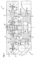
- diaphragm pump 1 has within a pump head 2 a ring diaphragm 3, which is clamped at its outer peripheral region between housing parts 4.5 and at its inner edge region between the housing part 4 and a clamping part 9.
- the annular diaphragm 3 defines an annular working space 6.
- a pump drive not shown here, is provided, which may preferably be designed as an eccentric drive or crank drive. It has a transmission element 7, which with a sleeve-shaped Drive element 8 is connected. This is connected at its other end to the ring diaphragm 3.
- the working chamber 6 is connected via inlet and outlet channels, not shown here, to an inlet valve and an outlet valve.
- the valves are preferably designed as plate valves.
- the ring diaphragm 3 and the drive element 8 connected thereto are shown in FIGS. 2 to 4.
- the ring diaphragm 3 is preferably connected to an end face of the sleeve-shaped drive element 8 by vulcanization.
- the annular diaphragm 3 consists of a rubber-elastic material, while the drive element 8 is formed for example by a steel sleeve.
- the drive element 8 is vulcanized into the annular membrane 3 and engages with a front end something in a groove 10 at the diaphragm bottom.
- an annular circumferential, rib-like connection and Stabilisierwulst 11 is provided, in particular in order to bring the pressure and train transmission from the drive element 8 better in the membrane.
- the connecting and stabilizing bead 11 is arranged approximately in a concentric region in the middle between outer edge 12 and inner edge 13 of the annular width of the annular membrane 3.
- Fig. 1 is also clearly visible that the annular membrane 3 is arranged to the working space 6 so that an approximately central orientation of the drive element 8 and the connecting and stabilizing bead 11 is present to the working space 6.
- the annular membrane is at least partially deformed into the working space 6, so that displaced therein conveyed medium becomes.
- the shaping of the working space 6 and the annular membrane 3 may be provided so that in top dead center, the membrane fills the working space virtually dead space.
- the annular diaphragm 3 is sealed relative to the housing parts 4 and 5 or also the clamping part 9 by an inner bead 14 and by an outer bead 15.
- the beads 14,15 engage in grooves 20,21 of the housing part 5 a.
- the ring-shaped working space having housing part 4, which forms a pump head part, has centrally to the central opening 16 of the annular membrane 3, a passage opening for a fastening screw 17 (Fig. 1) with the inside of the top plate 4 arranged, the inner edge of the membrane 13 under cross-clamping part 9 fixed and can be stretched to hold the ring diaphragm 3 against the top plate 4.
- the clamping part 9 is located within the annular space 18 formed by the sleeve-shaped drive element 8, so that this available space is utilized. Overall, a pump with low height can be realized by the direct drive transmission from a Exenterantrieb on the membrane and also by the space-saving arrangement of the clamping part 9 within the annular space 18.
- the adjoining the drive element 8 transmission element 7 may be a plastic part, which at its end facing the drive element 8 has a lug 19 on which the sleeve-like drive element 8 can be plugged and optionally connected by press fit or adhesive bond.
- the clamping part 9 can also be connected to the annular membrane by vulcanization, so that together with the drive element 8 a component consisting of three parts is formed. There are then only a few assembly parts that can be assembled in a short time.
- the membrane pump 1 is preferably designed as a feed pump for low flow rates at a comparatively high stroke frequency. For example, it is possible to realize delivery rates of 25 ml per minute, wherein 3,000 strokes per minute can be provided. The high number of strokes is required so that the valves work exactly and the tolerances of the valve sections do not have to be set too tight.
- the annular membrane 3 shown in perspective in FIGS. 3 and 4 together with the drive element 8 may for example have an outer diameter of 10 mm, so that the representations in FIGS. 3 and 4 would correspond approximately to a scale of 5: 1.
- the sleeve-shaped drive element 8 preferably has a continuous wall, but optionally also may have a wall provided with recesses or formed by at least partially by rods or fingers wall, so that a corresponding mass reduction or access to the inner annulus exist is. It should also be mentioned that although the annular membrane 3 preferably has a circular shape, it may also have a different shape.
- the attacking drive element 8 and the leading to the drive continuation of the membrane or the at least in the terminal region in the membrane preferably the same shapes as the membrane and thereby in particular as the working space 6 facing area or may be designed differently ,
- the annular membrane may have an elliptical shape as a whole or in some areas, which has advantages in conjunction with a crank mechanism and the associated pendulum motion of the drive element results.
- the pendulum movement preferably runs in the direction of the minor axis of the ellipse.
- a high-speed membrane-liquid pump in which a combination of high stroke rate with low flow rate is present and is still structurally simple and stable in construction.
- Such membrane pumps 1 are mainly used in laboratories or for microsystem applications. Even smaller embodiments of the membrane 2 than in the size shown in FIGS. 2 to 4 on a scale of 5: 1 are possible through the membrane 2 according to the invention.
Landscapes
- Engineering & Computer Science (AREA)
- Mechanical Engineering (AREA)
- General Engineering & Computer Science (AREA)
- Reciprocating Pumps (AREA)
Claims (17)
- Pompe à membrane (1) avec un espace de travail annulaire (6) et une membrane annulaire (3) qui est serrée au niveau de sa périphérie extérieure (12) et de sa zone de bord interne (13), dans laquelle les positions intérieure et extérieure de serrage de la membrane sont relativement fixes l'une par rapport à l'autre et dans laquelle un élément d'entraînement (3), relié à un entraînement de la pompe afin de déplacer la membrane annulaire (3), vient en prise entre les positions de serrage extérieure et intérieure, caractérisée en ce que, du côté tourné vers la membrane, l'élément d'entraînement (8) est réalisé avec une forme de douille ou d'anneau dont le diamètre correspond sensiblement à celui de l'espace de travail annulaire (6) et, par le biais de l'une de ses faces frontales annulaires, vient en prise perpendiculairement au plan de la membrane avec le côté de la membrane annulaire (3) tourné vers l'entraînement de la pompe afin de déplacer la membrane annulaire (3) et lui transmettre un mouvement de va et vient et en ce que l'élément d'entraînement (8) en forme de douille au moins par endroits est fixé au niveau d'un seul côté de la membrane annulaire (3) au côté opposé à l'espace de travail (6).
- Pompe à membrane selon la revendication 1, caractérisée en ce que l'élément d'entraînement en forme de douille (8) est réalisé sous la forme d'une douille cylindrique avec une paroi continue ou avec une paroi présentant des évidements ou avec une paroi formée au moins par endroits par des tiges ou des doigts.
- Pompe à membrane selon la revendication 1 ou la revendication 2, caractérisée en ce que l'entraînement de la pompe est de préférence réalisé sous la forme d'un entraînement à excentrique qui présente un élément de transfert (7) relié à l'élément d'entraînement en forme de douille (8) à l'extrémité de celui-ci opposée à la membrane annulaire (3).
- Pompe à membrane selon l'une des revendications 1 à 3, caractérisée en ce que la membrane annulaire (3) est serrée à force et/ou maintenue selon une liaison positive au niveau de la position de serrage intérieure de la membrane entre une partie de tête de pompe (4) présentant l'espace de travail annulaire (6) et une partie de serrage (9) qui peut être reliée à ladite partie de tête.
- Pompe à membrane selon la revendication 4, caractérisée en ce que la partie de serrage (9) disposée au niveau de la position de serrage intérieure de la membrane est reliée par un assemblage vissé, de préférence au centre, avec la partie de tête de pompe (4).
- Pompe à membrane selon la revendication 4 ou la revendication 5, caractérisée en ce que la partie de serrage (9) est reliée à la membrane annulaire (3) par vulcanisation.
- Pompe à membrane selon l'une des revendications 4 à 6, caractérisée en ce que la partie de serrage (9) au niveau de la position de serrage intérieure de la membrane se trouve à l'intérieur de l'espace annulaire (18) formé par l'élément d'entraînement (8) en forme de douille au moins par endroits.
- Pompe à membrane selon l'une des revendications 1 à 7, caractérisée en ce que la membrane annulaire (3) est serrée à force et/ou maintenue selon une liaison positive au niveau de son bord extérieur (12) entre la partie de tête de pompe présentant l'espace de travail annulaire (3) et une partie de boîtier qui peut être reliée à ladite partie de tête.
- Pompe à membrane selon l'une des revendications 1 à 8, caractérisée en ce que l'élément d'entraînement (8) en forme de douille ou d'anneau au moins côté membrane est en prise avec la membrane annulaire, par sa face frontale annulaire tournée vers la membrane annulaire (3), à peu près dans le prolongement d'une surface annulaire qui coupe l'espace de travail annulaire (6) sensiblement au milieu.
- Pompe à membrane selon l'une des revendications 1 à 9, caractérisée en ce que la membrane annulaire (3) présente un bourrelet de raccordement et de stabilisation (11) semblable à une nervure qui l'entoure de préférence sous forme annulaire, relié à l'extrémité en forme de douille ou d'anneau de l'élément d'entraînement (8), et en ce que, dans la zone de fixation, l'élément d'entraînement pénètre de préférence dans le bourrelet de raccordement et de stabilisation.
- Pompe à membrane selon l'une des revendications 1 à 10, caractérisée en ce que la face de la membrane annulaire (3) qui est tournée vers l'espace de travail (6) présente un revêtement, de préférence continu et notamment en PTFE.
- Pompe à membrane selon l'une des revendications 1 à 11, caractérisée en ce que l'élément d'entraînement en forme de douille (8) est relié à la membrane annulaire (3) de préférence par vulcanisation et/ou par une liaison positive ou à force.
- Pompe à membrane selon l'une des revendications 1 à 12, caractérisée en ce que l'élément d'entraînement en forme de douille (8) est en métal, de préférence en acier, et l'élément de transfert (7) relié à celui-ci est de préférence en matière plastique.
- Pompe à membrane selon l'une des revendications 1 à 13, caractérisée en ce que la membrane annulaire (3) présente un bourrelet extérieur (15) sur son bord extérieur (12) et un bourrelet intérieur (14) sur son bord intérieur.
- Pompe à membrane selon l'une des revendications 1 à 14, caractérisée en ce qu'elle est réalisée sous la forme d'une pompe de circulation pour de faibles débits de refoulement, de préférence dans une plage inférieure à 100 ml par minute, et pour une fréquence de travail élevée d'environ 50 Hz.
- Pompe à membrane selon l'une des revendications 1, 4 à 11, 14 ou 15, caractérisée en ce que l'élément d'entraînement (8) est relié d'un seul tenant à la membrane (3) et en ce qu'il présente un raccord pour l'accoupler avec l'entraînement de la pompe.
- Pompe à membrane selon la revendication 16, caractérisée en ce que des armatures en matériau flexible sont intégrées au moins par endroits dans l'élément d'entraînement (8) fait du même matériau que la membrane (3).
Applications Claiming Priority (2)
| Application Number | Priority Date | Filing Date | Title |
|---|---|---|---|
| DE102004002079 | 2004-01-15 | ||
| DE102004002079A DE102004002079A1 (de) | 2004-01-15 | 2004-01-15 | Membranpumpe |
Publications (2)
| Publication Number | Publication Date |
|---|---|
| EP1555434A1 EP1555434A1 (fr) | 2005-07-20 |
| EP1555434B1 true EP1555434B1 (fr) | 2006-10-25 |
Family
ID=34609560
Family Applications (1)
| Application Number | Title | Priority Date | Filing Date |
|---|---|---|---|
| EP04025738A Expired - Lifetime EP1555434B1 (fr) | 2004-01-15 | 2004-10-29 | Pompe à membrane |
Country Status (4)
| Country | Link |
|---|---|
| US (1) | US7373872B2 (fr) |
| EP (1) | EP1555434B1 (fr) |
| JP (1) | JP5371171B2 (fr) |
| DE (2) | DE102004002079A1 (fr) |
Families Citing this family (2)
| Publication number | Priority date | Publication date | Assignee | Title |
|---|---|---|---|---|
| US9377017B2 (en) * | 2012-11-15 | 2016-06-28 | Shenzhen Mindray Bio-Medical Electronics Co., Ltd. | Extended elasticity of pump membrane with conserved pump force |
| CN108757409B (zh) * | 2018-07-06 | 2023-08-25 | 珠海格力电器股份有限公司 | 隔膜组件、稳压泵及净水机 |
Family Cites Families (14)
| Publication number | Priority date | Publication date | Assignee | Title |
|---|---|---|---|---|
| US2731534A (en) * | 1948-02-26 | 1956-01-17 | Taylor Winfield Corp | Fluid pressure actuator for machine components |
| GB734294A (en) * | 1952-11-05 | 1955-07-27 | George William Webb | Improvements in or relating to pumping apparatus for use with boats |
| US3008427A (en) | 1959-02-11 | 1961-11-14 | Gen Motors Corp | Fuel pump |
| US3223045A (en) * | 1959-05-04 | 1965-12-14 | Chrysler Corp | Fuel pump |
| US3241494A (en) * | 1960-01-15 | 1966-03-22 | Acf Ind Inc | Fuel systems |
| US3252424A (en) * | 1960-01-15 | 1966-05-24 | Acf Ind Inc | Fuel systems |
| US3291064A (en) * | 1963-01-25 | 1966-12-13 | Gen Motors Corp | Diaphragm pump with annular pumping chamber |
| JPS61160666A (ja) * | 1984-12-29 | 1986-07-21 | Nippon Valqua Ind Ltd | ダイアフラムおよびその製造方法 |
| US5291822A (en) * | 1992-11-16 | 1994-03-08 | Orbital Walbro Corporation | Diaphragm for pressure regulators and method of making |
| DE4244619A1 (de) * | 1992-12-31 | 1994-07-07 | Knf Neuberger Gmbh | Verfahren zum Betreiben einer Membranpumpe sowie Membranpumpe zum Durchführen des Verfahrens |
| US5634391A (en) * | 1996-07-09 | 1997-06-03 | Westinghouse Air Brake Co. | Inert plastic coated flexible type diaphragm for application in a sanitary type pump |
| DE19802443C1 (de) * | 1998-01-23 | 1999-05-12 | Luk Fahrzeug Hydraulik | Pumpe |
| DE19819408A1 (de) | 1998-04-30 | 1999-11-11 | Freudenberg Carl Fa | Membranpumpe zur Förderung von gasförmigen oder flüssigen Medien |
| DE10233561B4 (de) * | 2002-07-24 | 2008-02-21 | Prominent Dosiertechnik Gmbh | Sicherheitsmembran für eine Membranpumpe |
-
2004
- 2004-01-15 DE DE102004002079A patent/DE102004002079A1/de not_active Withdrawn
- 2004-10-29 EP EP04025738A patent/EP1555434B1/fr not_active Expired - Lifetime
- 2004-10-29 DE DE502004001846T patent/DE502004001846D1/de not_active Expired - Lifetime
-
2005
- 2005-01-11 US US11/033,425 patent/US7373872B2/en active Active
- 2005-01-13 JP JP2005006629A patent/JP5371171B2/ja not_active Expired - Lifetime
Also Published As
| Publication number | Publication date |
|---|---|
| JP5371171B2 (ja) | 2013-12-18 |
| JP2005201278A (ja) | 2005-07-28 |
| US20050158190A1 (en) | 2005-07-21 |
| DE102004002079A1 (de) | 2005-08-11 |
| DE502004001846D1 (de) | 2006-12-07 |
| US7373872B2 (en) | 2008-05-20 |
| EP1555434A1 (fr) | 2005-07-20 |
Similar Documents
| Publication | Publication Date | Title |
|---|---|---|
| DE102007030311B4 (de) | Membranpumpe | |
| EP0057288B1 (fr) | Pompe à deux cylindres pour matières pâteuses notamment pompe à béton comportant un organe de commande qui pivote devant une plaque aux lunettes à côté des cylindres | |
| EP0733802B1 (fr) | Pompe à membrane façonnée | |
| DE102012000676A1 (de) | Verdrängerpumpe | |
| DE102020126241B4 (de) | Membrananordnung mit um den Membrankörper umlaufendem Ring sowie Sitzanordnung und Pumpenanordnung | |
| EP0367988B1 (fr) | Pompe à membrane | |
| DE2427528A1 (de) | Drosselventil, insbesondere fuer einen kraftfahrzeug-kuehlwasserkreislauf | |
| EP3851674A1 (fr) | Pompe à double diaphragme | |
| DE102020125567B4 (de) | Verbundmembran mit Einsatz und Öffnung umgebende Verdickung für Membranpumpen | |
| EP3447290A1 (fr) | Tête de pompe remplaçable pour pompe à diaphragme | |
| DE60315785T2 (de) | Pumpe | |
| EP0214394B2 (fr) | Pompe à diaphragme | |
| DE102014006503B4 (de) | Membranpumpe | |
| DE19844518A1 (de) | Hydraulischer Wegverstärker für Mikrosysteme | |
| DE112009000777B4 (de) | Handpumpe zum Pumpen von Kraftstoff | |
| DE10143978B4 (de) | Hydraulisch angetriebene Membranpumpe mit vorgespannter Membran | |
| DE3882949T2 (de) | Hin- und herbewegende schaltungsstrukttur für pumpe. | |
| EP1555434A1 (fr) | Pompe à membrane | |
| DE9416432U1 (de) | Dichtung | |
| DE202005002471U1 (de) | Membranpumpe | |
| EP2954208B1 (fr) | Compresseur à piston asymétrique | |
| EP1520988A1 (fr) | Pompe à membrane à actionnement hydraulique | |
| DE102006055556B4 (de) | Membranpumpe | |
| EP1602831A1 (fr) | Dispositif d'actionnement activé par un fluide sous pression | |
| DE69100260T2 (de) | Ventilanordnung. |
Legal Events
| Date | Code | Title | Description |
|---|---|---|---|
| PUAI | Public reference made under article 153(3) epc to a published international application that has entered the european phase |
Free format text: ORIGINAL CODE: 0009012 |
|
| AK | Designated contracting states |
Kind code of ref document: A1 Designated state(s): AT BE BG CH CY CZ DE DK EE ES FI FR GB GR HU IE IT LI LU MC NL PL PT RO SE SI SK TR |
|
| AX | Request for extension of the european patent |
Extension state: AL HR LT LV MK |
|
| 17P | Request for examination filed |
Effective date: 20050924 |
|
| GRAP | Despatch of communication of intention to grant a patent |
Free format text: ORIGINAL CODE: EPIDOSNIGR1 |
|
| GRAS | Grant fee paid |
Free format text: ORIGINAL CODE: EPIDOSNIGR3 |
|
| AKX | Designation fees paid |
Designated state(s): CH DE FR GB LI |
|
| GRAA | (expected) grant |
Free format text: ORIGINAL CODE: 0009210 |
|
| AK | Designated contracting states |
Kind code of ref document: B1 Designated state(s): CH DE FR GB LI |
|
| REG | Reference to a national code |
Ref country code: GB Ref legal event code: FG4D Free format text: NOT ENGLISH |
|
| REG | Reference to a national code |
Ref country code: CH Ref legal event code: EP |
|
| REG | Reference to a national code |
Ref country code: CH Ref legal event code: NV Representative=s name: HANS RUDOLF GACHNANG PATENTANWALT |
|
| REF | Corresponds to: |
Ref document number: 502004001846 Country of ref document: DE Date of ref document: 20061207 Kind code of ref document: P |
|
| GBT | Gb: translation of ep patent filed (gb section 77(6)(a)/1977) |
Effective date: 20070126 |
|
| ET | Fr: translation filed | ||
| PLBE | No opposition filed within time limit |
Free format text: ORIGINAL CODE: 0009261 |
|
| STAA | Information on the status of an ep patent application or granted ep patent |
Free format text: STATUS: NO OPPOSITION FILED WITHIN TIME LIMIT |
|
| 26N | No opposition filed |
Effective date: 20070726 |
|
| REG | Reference to a national code |
Ref country code: CH Ref legal event code: NV Representative=s name: GACHNANG AG PATENTANWAELTE, CH |
|
| REG | Reference to a national code |
Ref country code: FR Ref legal event code: PLFP Year of fee payment: 12 |
|
| REG | Reference to a national code |
Ref country code: FR Ref legal event code: PLFP Year of fee payment: 13 |
|
| REG | Reference to a national code |
Ref country code: FR Ref legal event code: PLFP Year of fee payment: 14 |
|
| REG | Reference to a national code |
Ref country code: FR Ref legal event code: PLFP Year of fee payment: 15 |
|
| PGFP | Annual fee paid to national office [announced via postgrant information from national office to epo] |
Ref country code: GB Payment date: 20231025 Year of fee payment: 20 |
|
| PGFP | Annual fee paid to national office [announced via postgrant information from national office to epo] |
Ref country code: FR Payment date: 20231023 Year of fee payment: 20 Ref country code: DE Payment date: 20231002 Year of fee payment: 20 Ref country code: CH Payment date: 20231102 Year of fee payment: 20 |
|
| REG | Reference to a national code |
Ref country code: CH Ref legal event code: PK Free format text: BERICHTIGUNGEN |
|
| REG | Reference to a national code |
Ref country code: DE Ref legal event code: R071 Ref document number: 502004001846 Country of ref document: DE |
|
| REG | Reference to a national code |
Ref country code: CH Ref legal event code: PL |
|
| REG | Reference to a national code |
Ref country code: GB Ref legal event code: PE20 Expiry date: 20241028 |
|
| PG25 | Lapsed in a contracting state [announced via postgrant information from national office to epo] |
Ref country code: GB Free format text: LAPSE BECAUSE OF EXPIRATION OF PROTECTION Effective date: 20241028 |
|
| PG25 | Lapsed in a contracting state [announced via postgrant information from national office to epo] |
Ref country code: GB Free format text: LAPSE BECAUSE OF EXPIRATION OF PROTECTION Effective date: 20241028 |