EP1555456A2 - Commande d'un train épicycloidal à démarreur/générateur comme auxiliaire par commande de la vitesse du démarreur/générateur - Google Patents
Commande d'un train épicycloidal à démarreur/générateur comme auxiliaire par commande de la vitesse du démarreur/générateur Download PDFInfo
- Publication number
- EP1555456A2 EP1555456A2 EP04030074A EP04030074A EP1555456A2 EP 1555456 A2 EP1555456 A2 EP 1555456A2 EP 04030074 A EP04030074 A EP 04030074A EP 04030074 A EP04030074 A EP 04030074A EP 1555456 A2 EP1555456 A2 EP 1555456A2
- Authority
- EP
- European Patent Office
- Prior art keywords
- pin
- groove
- planetary gear
- speed
- link
- Prior art date
- Legal status (The legal status is an assumption and is not a legal conclusion. Google has not performed a legal analysis and makes no representation as to the accuracy of the status listed.)
- Withdrawn
Links
Images





Classifications
-
- F—MECHANICAL ENGINEERING; LIGHTING; HEATING; WEAPONS; BLASTING
- F02—COMBUSTION ENGINES; HOT-GAS OR COMBUSTION-PRODUCT ENGINE PLANTS
- F02N—STARTING OF COMBUSTION ENGINES; STARTING AIDS FOR SUCH ENGINES, NOT OTHERWISE PROVIDED FOR
- F02N11/00—Starting of engines by means of electric motors
- F02N11/04—Starting of engines by means of electric motors the motors being associated with current generators
-
- F—MECHANICAL ENGINEERING; LIGHTING; HEATING; WEAPONS; BLASTING
- F16—ENGINEERING ELEMENTS AND UNITS; GENERAL MEASURES FOR PRODUCING AND MAINTAINING EFFECTIVE FUNCTIONING OF MACHINES OR INSTALLATIONS; THERMAL INSULATION IN GENERAL
- F16H—GEARING
- F16H3/00—Toothed gearings for conveying rotary motion with variable gear ratio or for reversing rotary motion
- F16H3/44—Toothed gearings for conveying rotary motion with variable gear ratio or for reversing rotary motion using gears having orbital motion
- F16H3/46—Gearings having only two central gears, connected by orbital gears
- F16H3/48—Gearings having only two central gears, connected by orbital gears with single orbital gears or pairs of rigidly-connected orbital gears
- F16H3/52—Gearings having only two central gears, connected by orbital gears with single orbital gears or pairs of rigidly-connected orbital gears comprising orbital spur gears
- F16H3/54—Gearings having only two central gears, connected by orbital gears with single orbital gears or pairs of rigidly-connected orbital gears comprising orbital spur gears one of the central gears being internally toothed and the other externally toothed
-
- F—MECHANICAL ENGINEERING; LIGHTING; HEATING; WEAPONS; BLASTING
- F16—ENGINEERING ELEMENTS AND UNITS; GENERAL MEASURES FOR PRODUCING AND MAINTAINING EFFECTIVE FUNCTIONING OF MACHINES OR INSTALLATIONS; THERMAL INSULATION IN GENERAL
- F16H—GEARING
- F16H3/00—Toothed gearings for conveying rotary motion with variable gear ratio or for reversing rotary motion
- F16H3/003—Toothed gearings for conveying rotary motion with variable gear ratio or for reversing rotary motion the gear ratio being changed by inversion of torque direction
- F16H3/005—Toothed gearings for conveying rotary motion with variable gear ratio or for reversing rotary motion the gear ratio being changed by inversion of torque direction for gearings using gears having orbital motion
Definitions
- the present invention relates to a planetary gear with the components housing, sun gear, Ring gear, bridge with planet gears, two opposite opening and closing acting coupling units K1 and K2 a clutch, and a clutch actuator, wherein a first component forms a first transmission connection and with the drive shaft of a first drive unit, preferably an internal combustion engine, is connectable, and a second component forms a second transmission connection, preferably a pulley, wherein the first and second components through the Coupling units K1 or K2 frictionally connected to each other.
- a first drive unit preferably an internal combustion engine
- the invention relates to a method for targeted switching of a two gear ratios comprehensive planetary gearbox with two gearbox connections.
- Planetary gear z. B. used on crankshafts of internal combustion engines, wherein Starter generators are operated in the power take-off, as z. B. for starter generators and internal combustion engines comprehensive drive units in the applicant German Patent Application DE 199 41 705 A1 is described.
- the Gear ratio stages automatically as a function of the operating mode of the transmission or set the drive unit, so z. B. during startup of the starter generator is reduced with a gear ratio.
- the internal combustion engine helps to allow a higher crankshaft speed than the starting speed.
- drive units with planetary gears are known in which the gear ratio Shadowed from the outside.
- An example of a switched clutch is in DE-PS 41st 12 215 indicated.
- the present object is characterized by a planetary gear of the type mentioned by solved that the clutch actuator a link disc with groove and a in the groove of the link plate guided pin, where link plate and pin relative can be rotated by a limited angle to each other.
- the present object is achieved by a method in which a targeted switching a two-speed planetary gearbox, with two gearbox connections, a slot comprising a groove with a guided in the groove pin to Transmission control and transmission of the transmission torque, characterized in that the Switching by means of a speed-controllable drive unit acting on the second gearbox connection by selectively accelerating or decelerating their speed relative to the speed of the second gear connection is made by the in the groove of the link plate guided pin relative to this twisted by an angle, and depending on the size of the Angle rotation two with respect to opening and closing opposite acting coupling units K1 and K2 a clutch operated, the switching from a translation stage to enable others.
- the link plate is preferably provided with a radially or axially extending groove, wherein, relative to the link plate, the axial direction of the pin in an axial direction engages in the groove, or engages in the radial direction of the pin in the radial direction in the groove.
- the groove has left and right side stop points to the rotation angle between pin and link plate at left and right side relative rotation to this limit.
- This defined relative rotation can be advantageous for the circuit of Geretetechnik GmbHsverphaseftnisses be used from one level to another. Because the pin within the groove at two defined points once to the left and once to the right on the link plate is applied, can be left and right-handed moments by means of the combination Pin-link disc transfer.
- the return can be designed so that it is between the link plate and pin Can transmit torque, z. B. when the pin at the high end of the return in one Groove portion is applied, which deviates from the pure radial direction. Furthermore, the groove itself have a return by not making an acute angle at an investment point as 90 ° forms.
- the groove advantageously has a self-contained Structure up so that the pin makes a point inside the groove after passing through the entire Groove, or part of the groove, comes back to the same point.
- This can be any point and thus every stop point within the groove can be reached as often as desired, whereby the connected with a groove position shank or control functions as often executable are.
- the link plate several about to the middle of the gate concentric or axially adjacent groove sections, which are interconnected at least once with each other by a groove.
- a variety of control options In particular, it can be achieved that the relative rotation of link plate and Pin must be greater than one revolution to switch from a switching state, eg. B. from an anchor point, to come to a second.
- the left and right attachment points be arranged symmetrically.
- the grooves are circular section on a preferably round link plate arranged, with their radius changes at a predetermined angular distance. This advantageously opens up the possibility that the guided in the groove pin when passing through The groove can perform control functions that not only depend on its angular position also depend on its radial position on the link plate, creating the control options be extended.
- a centrifugal lock which engages in the groove, when a certain speed of the link plate is exceeded or fallen below.
- This will be the pin is restricted by the centrifugal lock in its movement within the groove.
- the centrifugal lock is placed near a stop point to at a certain speed or a speed range the pin between anchor point and To hold centrifugal lock. This allows the pin guided in the link disc to be angularly and take over radius-dependent and speed-dependent control functions.
- the grooves are mounted in a front side of a pulley z. B. is arranged to the planetary gear, in which case this end face as a link plate serves, in which a pin engages for control purposes.
- an independent link disc also with the ring gear or with another rotatable component (bridge, sun gear, Pulley) of the planetary gear be connected.
- the clutch actuator also advantageously includes a thread to an angular rotation To convert between pin and link in an axial movement. So that can then z. B. via suitable lever control z. B. of coupling units can be achieved.
- the clutch actuator includes one of the threads in axially guided coupling ring, which in axial movement, the coupling units K1 and K2 open and close, which are preferably designed as multi-plate clutches, so in a simple way in a planetary gear different translations thereby be switched that by the relative rotation of pin and link plate a Angle movement is converted into a linear coupling movement.
- the planetary gear between the housing and the pulley a Ratchet mechanism, with a ram ring for connecting the housing with the ring gear, and / or it may have at least two radial sections and the pin can with a biased by means of an elastic element flyweight be connected, the pin by the flyweight speed dependent in the radial Portions of the groove is guided.
- a speed-controllable drive unit is preferably a Starter generator used.
- Planetary gear can be selectively switched by means of the starter generator, z. B. can be the gear ratios of the transmission according to the requirements turn. This is then z. B.
- the angular rotation between pin and link plate by means of a thread in one for angular rotation proportional axial movement to open or close the coupling units K1 or K2 implemented.
- a relative angular rotation of about 340 ° or about 700 ° for opening and shooting of the coupling units K1 or K2, wherein the Groove at an angular distance of approx. 340 ° left and right attachment points for torque transmission has between pin and link plate.
- a preferred embodiment of the method according to the invention is that when not rotating first gearbox connection by repeated reversal of the direction of rotation of the speed-controllable Drive unit, the link disc and the pin on the rotating gearbox connection is connected to the housing.
- a further preferred method is by a radial movement of the with a Fliehgewood connected pins along a radially extending groove portion a Interruption of a torque transfer from the first to the second gearbox connection scored, wherein the centrifugal weight by means of an elastic element biased is.
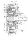
- Figure 1 shows a planetary gear 50 with the switching mechanism according to the invention.
- a wave 2 z. B. a crankshaft of an internal combustion engine
- the front side is a chain, or toothed belt wheel 2a for driving the camshaft by means of a shaft screw 2b attached.
- the attachment takes place for example by means of a frictional connection between the wheel 2a and the end face of the shaft 2, by tightening the shaft screw 2b.
- a wedge 2c serves for the angular orientation of wheel 2a and shaft 2.
- wheel 2a circlip 1 b be used.
- On the wheel 2a is also by means of screws 1c fixed a damper 1, which is fixedly connected to the shaft 2 and with rotation of the shaft 2 with this is revolving.
- On the shaft screw 2b are also essential parts of the planetary gear 50 rotatably mounted or are fixedly formed on this.
- a web 3 of the planetary gear is fixed trained with this.
- the web 3 comprises axes 16 on which planet gears 16a are rotatable are stored.
- the teeth of the planet gears 16a engage in an inner sprocket 19 of a Ring gear 20 a.
- Via a connecting web 21 is a link 8, a first essential Part of the switching device according to the invention forms, fixedly connected to the ring gear 20, between the connecting web 21 and the web 3 on the front side of the axes 16 for adjusting the axial play of the planet gears 16a and to reduce the friction a thrust bearing 17 is attached.
- the thrust bearing 17 is preferably a friction ring, the z. B. may consist of plastic.
- a sun gear 5 of the planetary gear 50 rotatably supported on this.
- the storage takes place z. B. by means Needle roller bearings, preferably needle sleeves 15, wherein also a different storage can be selected can.
- the pulley 4 z is at the outside end face. B. by means firmly connected to a weld.
- the shaft 2 with the Starter generator (not shown) connected via a belt, with other units such as B. an air conditioner can be driven.
- the shaft screw 2b is the front side with a z. B. attached to the pulley 4 cover 4 b covered.
- a hollow shaft 9 e Between the web 3 and a Tilger 1 is a hollow shaft 9 e, the second forms a substantial part of the switching device according to the invention.
- This is also rotatable mounted on the shaft screw 2b, wherein it comprises a pin connection 9a to a fixed To hold connection with a pin 9 engaging in a groove of the crank plate 9.
- the Hollow shaft 9e is axially movable only in the context of a minimal bearing clearance, which also by means of a thrust bearing 25 is adjustable.
- the thrust bearing 25 can also as Friction disc be formed.
- the hollow shaft 9e comprises an external thread 10, on a nut 10a is rotatably arranged.
- the nut 10a is via a Hohlradtagen 23 connected to the ring gear 20 so that the nut 10 a relative to the ring gear 20th axially displaceable by rotation on the hollow shaft 9e, wherein between nut 10a and Ring gear 20 always a rotational connection should exist.
- This can be z. B. achieved thereby be that a toothing in the outer region of the ring gear 23 in the sprocket 19 of the ring gear engages, and a corresponding axial toothing in the interior of the Hohlradtagen 23 in a complementary to this toothing on the nut outside intervenes.
- the transmission 50 is rotatably mounted on the nut 10a, a coupling ring 10b attached.
- this is axially by a on the mother 10a molded projection and by a projection opposite to the mother 10a applied circlip 10c fixed.
- This z. B. by means of a Friction disc 10e or other bearing element for axial bearing and bearing clearance adjustment this set
- the coupling ring 10b can be relative to the mother 10a turn to this, but he in the axial direction, due to the axial fixation with the mother, being moved with this.
- Form radial parts 10d of the coupling ring 10b Pressure plates of a first part of a clutch 7, which here designed as a multi-plate clutch is.
- the pin connection 9a leads, at the axial direction, a penetration element 9c is welded, by means of the passage element 9c through one on the coupling ring 10b radially arranged opening.
- a penetration element 9c is welded, by means of the passage element 9c through one on the coupling ring 10b radially arranged opening.
- the hollow shaft 9e is rotationally locked connected to the coupling ring 10b, that is, a relative rotation the hollow shaft 9e to the coupling ring 10b is prevented.
- a penetration element 9c is by means of elastic elements, such as. B.
- the clutch 7 therefore comprises two coupling units K1 and K2, wherein the coupling unit K1 z. B. is closed by friction, by the stationary housing 6 facing radial parts 10d of the coupling ring 10b are brought to the housing 6 to the plant.
- the coupling unit K2 is closed by the fact that the coupling ring 10b with its radial parts 10d to the pressure plates located on the absorber 1 1a and 1b for Plant is brought.
- Sealing elements 14, 24 and 24a seal the running in oil or fat planetary gear set.
- the gate circuit consisting of link plate 8, pin 9, Leaf springs 9b, pin connection 9a, hollow shaft 9b, nut 10a, thread 10, coupling ring 10b and passage member 9c is arranged between the drive and output so that they also ensures the corresponding frictional connection, that is over parts (essentially over Guide disc 8, pin 9, passage member 9c and parts of the coupling ring 10b) of Sliding the torques are transmitted from the shaft 2 to the pulley 4 or the other way around.
- the coupling units are arranged so that only one Clutch can be closed, the other is then open.
- the relative angular rotation between pin and link plate is by stop points in the link plate limited, so that a rotation of about 340 ° is possible. This is the maximum at the same time Twisting of the thread 10 and thus the movement of the radial parts 10d of the coupling ring, which act as pressure plates and attached to the outer circumference of the coupling ring 10b are.
- the thread 10 is advantageous in the embodiment shown in FIG arranged far inside, to the lowest possible frictional torque of the thread at high axial force to be able to produce.
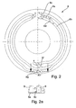
- the link disc 8 comprises a preferably self-contained groove 8a.
- groove sections as shown in the exemplary embodiment, can be arranged almost concentrically with one another in sections.
- the pin 9 is guided at a rotation of the groove and pin. Transmits z. B. the engine via the transmission power to the pulley 4, the pin 9 is at the point 1 of the backdrop, and the torque is transmitted to this stop point.
- the scenery 8 rotates clockwise and takes the pin, so to speak. For the transmission shown in Figure 1, this results in a ratio of 1: 1, so it is transmitted power from the crankshaft to the starter generator, which operates as a generator.
- the starter generator is thus driven, which is why such a state is also referred to as "train 1: 1".
- the groove shape in Figure 2 allows in position 2 on the gate 8 a booster operation, that is, it will be transmitted power and torque from the starter generator to the backdrop.
- the starter generator is driven as a motor with a slightly higher speed than it would have due to the "train 1: 1” operation.
- the pin moves away from the stop point, which is also referred to as point 1, and is rotated by the slot in an attachment point 2, twisted in the direction of the cam slip, via which it transfers torque to the internal combustion engine or the shaft 2. This condition is referred to as "thrust 1: 1" because the starter generator applies a positive torque M + .
- the anchor point 2 is only so far away from the anchor point 1, that maintained by this rotation of backdrop and pin, the coupling units essentially their positions.
- By speed reduction on the starter generator or by acceleration of the engine relative to the starter generator pin 9 is again rotated in the other direction and comes - guided by the groove (and a return 8c, see below) - in the gate position 3.
- the state again "Train 1: 1" given because position 3 is the same angle to the gate position 1, and thus no adjustment of the coupling device takes place.
- each stop point is an axial Return 8c arranged, which is shown schematically in Figure 2a.
- the return 8c is formed wedge-shaped and engages in the groove 8a, so that a pin 9, the groove 8a only in one direction, otherwise at a steep end, which is preferred is formed perpendicular to the groove 8a, comes to rest.
- the wedge 8c a Form stop point for the pin, if this arranged in the groove approximately in the direction of rotation is.
- the return 8c is z. B. by means of a plate 8e on the opposite Side of the Pineingriffs attached. In this case, the return resiliently on the plate 8e or be held on the link plate 8 or be firmly connected to this.
- In the second Trap becomes the pin displacement (perpendicular to the groove) due to the rebound by a spring held pin 9 balanced, z. B. by means of leaf springs 9b, as shown in Figure 1 is.
- the recesses 8c are essentially used to guide the pin 9. So z. B. ensures that the pin is continued defined after leaving an anchor point, wherein with closed slide tracks the same anchorage point again after a run the groove 8a is reached. In FIG. 2, the recesses 8c are identified by lines 8d.
- a gear change can not only by accelerating the starter generator but be enforced by strong deceleration of the shaft 2, since also here a corresponding Twist of pin 9 and backdrop 8 result.
- This is z.
- a strong braking with a gear engaged eg in an ABS braking
- a gear upshift e.g in a gear upshift.
- This would result in the PTO to undesirably high braking accelerations and to a possible overload of the components.
- the state of the opened clutches maintained until the braking process is completed.
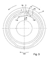
- FIG. 3 An example of an embodiment of a backdrop with centrifugal lock is shown in Figure 3.
- a centrifugal lock 13 engages in a region of the groove 8 a at high speed and locked the pin 9 a rotation in the direction of the switching position 5 of the high gear ratio.
- the centrifugal lock is rotatable at one end by means of a bearing 13b on the link plate 8 fixed and biased radially inwardly with a spring 13 a, so that they at small speeds does not come into effect. Only at higher speeds, when the centrifugal force is sufficiently high, the centrifugal lock rotates in the groove 8a. As a result, z. B. a Switching from the low to the high gear ratio at high speeds prevented become.
- an axial recess 8g attached.
- This can be with the internal combustion engine (Shaft 2) in this position, when both clutches are opened, through the Starter generator z. B. an auxiliary pulley located on the pulley, z. B. a Klmastrom, operated (switch position 7).
- the couplings can be designed without torque overlap.
- a friction device can, for. B. a spring plate 11 (see FIG 1) serve.
- the Spring plate 11 z. B. radially shifted slightly by the pin something in the radial Moves direction, then to a kind of ratchet structure 12 on the housing to the plant come. The radial displacement of the pin is achieved via the groove 8 a in that this approaching the backdrop.
- the Rateschenfashioned is designed so that when driving the Auxiliary units with open coupling units K1 and K2 in the direction of positive direction of rotation of the generator (drive direction of the ancillaries) only a small drag torque is generated, whereby the starter generator loaded by the planetary gear little becomes. In the other direction, however, the drag torque is higher, the friction in the To overcome thread 10 better, whereby a shift is only possible.
- a particular advantage of the embodiment shown in Figure 1 is that only the planetary gear running in oil lubrication, but not the other components, especially not the Clutch and the gate circuit.
- the Clutches also work with the high dry friction coefficient, thereby reducing the required Contact forces are smaller.
- the drag losses are lower than those in clutches occur in an oil bath.
- the radial shaft seals 24 and 14 for Seal of the planetary gearset be mounted far in, resulting in lower Drag torques in the planetary gear set and thus a better efficiency.
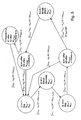
- FIG. 4 shows a simplified linear representation of the planetary gear according to the invention from Figure 1.
- the clutches K1 and K2 are shown, which by means of Thread 10 are shifted when switching the transmission.
- the torque is from the shaft 2 first transferred to the web 3.
- a part of the torque by means the planet gears 16a transferred to the ring gear 20 and a part of the sun gear 5, according to the associated transmission ratios.
- the link plate 8 At the ring gear 20 is the link plate 8, in which the pin 9 engages.
- the backdrop 8 corresponds approximately to that shown in FIG. If the pin 9, for example, from shift position 1 of the gate 8 to switch position 5 moves, so K1 closes and K2 opens.
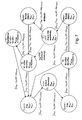
- FIG. 5 shows a state diagram which shows the various switching states of the planetary gear mechanism from FIG. 1 with the link disk from FIG.
- the numbers in the circles indicate the corresponding switching states of the scenery.
- M KW and M RS are the respective torques on the crankshaft 2 and the pulley 4, where "+” means an increase and “-” means a decrease of the torque.
- M Tow denotes the drag torque of the clutch, which can be positive “+” or negative “-” and is a function of the speed (f (delta n)).
- the adjustment angle between pin 9 and crank plate 8 is generally denoted by Dj and results from the time-integrated speed difference of crankshaft 2 and pulley 4 (nKW and nRS) when the gear ratio is 1: 1, otherwise the gear ratio (iPlanet) must be considered ,
- the Dj indicated in FIG. 5 are the required angular rotations in order to achieve the corresponding switching states on the link disk 8.
- the state diagram clarifies that the states can only be traversed in one direction due to the axial recesses, whereby two possible paths result in the switching state 4. If the starter generator is slower than the shaft 2, the groove area 8b (FIG. 2) leads to the switching position 1 on the link disk.
- Figure 6 shows another link plate for a transmission according to the invention.
- a centrifugal force lock 13 is mounted in the groove portion 8b is, which switches from the low gear ratio to the high gear ratio of the transmission.
- the Centrifugal lock 13 blocks the groove 8b at high speeds, so that an upshift of Translation is not possible.
- a special feature of this scenery disc is that they are part of the Front side of the pulley 4 is, wherein the groove 8a incorporated in the pulley end face are.
- the gate includes an additional recess 8h in the groove 8a, thereby it is possible to switch a generator high mode (switching position 5 '), that is the starter generator and the ancillaries are with 3: 1 or with the gear ratio driven (“thrust 3: 1").
- the groove portions 8i and 8k serve the outer To achieve switching positions 1 and 5 faster, without having to drive through the entire groove. This can z. B. from “train 1: 1” in the shaft position 3 to "thrust 1: 1" in the shaft position. 2 be switched faster without opening the coupling units. Likewise of “thrust 3: 1" in the outer switching position 5 without opening the coupling units in the "Train 3: 1" to be switched. "
- FIG. 7 shows the state diagram associated with FIG. 6 analogously to FIG. 5.
- a new switching state 5 ' in which the starter generator is operated in high operation. Due to the switching state 5 'results in a further shaft state 5 (outside), where a "thrust 3: 1" is possible, that is, where the starter generator the shaft 2 drives.
- a centrifugal lock can be used be engaged at shaft speeds less than 500 U / min in the groove and the pin to her to Plant comes, whereby a "thrust 3: 1" operation is switched. Exceeds the shaft speed a critical speed, so the centrifugal force protection opens the groove and there is a switch the translation of z. B. 3: 1 to 1: 1, whereby the ancillaries protected against overspeeding become.
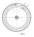
- Figure 8 is analogous to Figure 6 link disc 8 with the same switching states, however shown without centrifugal lock, but also attachable.
- the difference to The backdrop of Figure 6 is that a rotation of about 700 ° between pin 9 and link plate 8 is necessary to switch between the coupling units K1 and K2.
- this solution is disadvantageous with a higher Friction wear connected to pin 9 and groove 8a.
- Figure 9 shows a further embodiment of the transmission according to the invention, in the ring gear 20 is permanently connected to the stationary housing 6.
- the Shaft 2 crankshaft
- the bridge 3 is connected to the sun 5, and in the lower translation (1: 1), the pulley 4 is connected directly to the web 3.
- the advantages are characterized by the far inner coupling units and given the internal thread, resulting in small friction moments to let.
- the disadvantage is that at the small translation (1: 1) the planets empty revolve, causing friction losses.
- the pin 9 is held via a spring-trained pin connection 9a, which on a Passage element 9c is mounted, which (eg star-shaped) by a Coupling ring 10b attacks, the pressure plate for opening and closing the coupling units K1 and K2 carries.
- the penetration element 9c is with respect to axial displacement by means of a securing ring 22 or a corresponding thrust bearing secured against axial displacement, as well as a screw sleeve 15, which is located on a located in the center of the transmission screw 14a.
- the Screw 14a is axially movable and includes a thread 10 and a thread 10 ' with reverse slope.
- FIG. 10 shows a further exemplary embodiment of a planetary gear according to the invention with a structure similar to that shown in FIG.
- the thread is 10th arranged outside and the pin 9 and the crank disc 8 are in the radial direction between the coupling units K1, K2 and the ring gear 20, the link 8 on the ring gear 20 and the pin 9 is attached to the coupling carrier.
- a special spring band thread 30 (“Raberfeder") is used, which is a special development representing the applicant and is described in more detail in DE 100 81 936.
- spring band thread 30 is a resilient flat steel (spring band) helically wound, wherein its flat side is arranged in the radial direction.
- spring steel z When used as a thread is the spring steel z.
- Figure 11 shows schematically a similar embodiment according to the invention as in Figure 10, wherein the couplings K1, K2 and the spring band thread 30, as well as slide 8 and pin 9, 9 '(9 and 9 'are connected to a leaf spring 9b, not shown) arranged in a different position are.
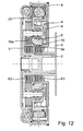
- FIG. 12 shows a further embodiment of the planetary gear according to the invention, wherein the pulley 4 with the ring gear 20 and the crankshaft 2 with the web 3 is connected.
- the sun gear 5 is optionally connected to the stationary housing 6 (high Translation, z. B. 3: 1) or the web (small translation, eg 1: 1) connected. Furthermore, will the sun gear 5 is centered by three stepped planet wheels 16a and has a thread inside 10 trained.
- the link plate 8 is supported on the housing 6 or on the web 3 via the Hollow shaft 9e, which includes an external thread, which with the thread 10 of the sun gear 5 is in operative connection.
- the pin 9 is connected to the sun gear 5. Will the pin 9 relative shifted to the backdrop 8, so the hollow shaft is rotated 9e and is displaced axially. As a result of this axial movement, the clutches K1 and K2 become corresponding to the preceding ones Embodiments shifted.
- adjusting thread 10 and the couplings K1, K2 are arranged inside the planetary gear set, with small friction moments at the adjusting thread and outside space for the arrangement of absorber and Vibration damper is.
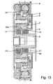
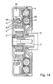
- Figure 14 shows an embodiment of a planetary gear, in which the multi-plate clutches are replaced by jaw clutches 41, 42, wherein the creation of the couplings means an actuator 40 takes place, which replaces the gate circuit.
- Jaw clutches 41, 42 requires that with the starter generator always the Synchronous speed of each gear can be approached to the Claw clutches 41, 42 to switch into the respective recesses 42.
- the advantage is that switches in any switching state as often and thus a change of train and Thrust can be achieved. It is also advantageous that at engine standstill (standing wave 2) almost no drag torque occur, causing ancillaries such. B. occur, whereby ancillaries such. As air conditioners, operated with good efficiency can be.
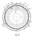
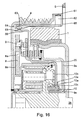
- FIG. 16 and 17 a transmission is shown, in which a link plate 8 of FIG. 15 is an overall front view of a section of FIG. 16.
- FIG is that shows a modified planetary gear according to the invention.
- FIG. 17 shows in one enlarged detail of the individual functional elements of the modified transmission.
- the link disc 8 is shown in a switching position for a ratio of 1: 1.
- the slide track 8a has at the switching points 1,3 and 5, 5 'a radially extending Groove section on. If the pin has arrived in this groove section, he can not initially leave. He is form-fitting with very little play by a flyweight 67, with which the Pin is connected, held in the groove.
- the game is designed much smaller, causing the pin within the Nutbegrenzonne during a pull / push change (a reversal of the currently applied torque) only little is moved. This results in a lower noise. Furthermore, vibrations occurring in the drive can not cause unwanted gear changes. Furthermore, in a shaft position without intervention of the starter generator as often as desired be changed between train / thrust.
- a changeover of the gear ratio always takes place when it is exceeded or falling below a limit speed at which the pin 9 from the inside out or vice versa migrates along the radially formed groove portion.
- the disturbances of the switching process frictional forces caused by moments transmitted at the pin reduced by the constantly existing vibrations, since these a change of plant of Pins cause, whereby always prevail for a short time low frictional forces.
- To this Time pin 9 can then with increasing centrifugal force to the outside or at decreasing Centrifugal force to move inwards.
- the pin switched by the starter generator from the ratio 1: 1 to a higher one (eg 3: 1), since he is now on the inner groove section.
- the switching process z.
- Figure 16 shows an analog planetary gear to that in Figure 1, but with modified Sliding link and additional connection and control elements on the housing and on the pulley. The same parts are the same.
- the ring gear 20 is separated from the housing when the shaft screw 2b is stationary, so that this is free to spin.
- the release and connection of the Ring gear 20 with the housing by means of a support ring 66 and pins 64 which are in recesses 69 can engage in the support ring 66.
- the pins 64 are radial for this purpose movably attached to a ring 65 made of spring steel, this being for improvement have the radial mobility of the pins 64 in the vicinity of recesses can, so that a spring-like mounting of the pins is achieved.
- the ring 65 simultaneously serves to support the torque and is connected to the housing 6.
- a rotation of the Ramprings 63 connects by 30 ° and solves a connection between the spring plate ring 65 and carrier ring 66.
- the Rampring is at least partially resilient, because the pins 64 and the recesses 69 on the carrier ring 66 are not always synchronous stand, whereby the pin biased if necessary, and then by means of the starter generator the correct angular position can be approached. To control an actuator to save the Ramping 63, this is targeted twisted by the generator.
- a freewheel plate 62 which on the pulley 4 is fixed by means of a ring 61, and rotated with this. Femer becomes the fact exploited that the pulley 4 in operation relative to the housing always only right (operating direction) moves, bringing a turn in the other direction can be used for switching.
- the freewheel plate 62 includes spring-trained wedge-shaped elements, depending on the direction of rotation of the pulley 4 with different Angles on Rampring 63 come to the plant. This will create a "ratchet mechanism" achieved, by means of which the Rampring 63 are passed over or twisted can.
- the ram ring 63 is skipped and maintains its position relative to the spring washer. Turns the pulley 4 in the other direction, the ram ring is taken and the pins 64 can with the recesses 69 of the support plate are connected, creating a connection between ring gear 20 and housing 6 is made. At higher speeds in the operating direction the friction between freewheel plate and ram-ring is thereby reduced that the wedge-shaped elements of the freewheel plate 62 by the centrifugal force to the outside Move away from Rampring 63. This increases the efficiency in normal operation.
- Pos. designation Pos. designation Pos. designation Pos. designation 1 absorber 21 connecting web 101 1b circlip 22 circlip 102 1c screw 23 Hohlradtagen 103 1d pressure plate 24 sealing element 104 2 Shaft, crankshaft 24a sealing element 105 2a Chain, timing belt, wheel 25 thrust 106 2 B shaft screw 30 Spring band thread 107 2c wedge 40 actuator 108 3 web 41 claw clutch 109 4 pulley 42 claw clutch 110 4b cover 43 recesses 111 5 sun 50 planetary gear 112 6 casing 61 ring 113 7 clutch 62 Freewheel sheet 114 8th Scenery, backdrop 63 Rampring 115 8a groove 64 pen 116 8b Groove, groove area 65 Spring steel ring 117 8c return 66 support plate 118 8d Return, line 67 flyweight 119 8e plate 68 Return spring 120 8f Return in the groove 69 recess 121 8g axial return 72 122 8i groove sections 73 123 8k groove sections 74 124 9 Pin code 75 125 9 ' Pin code
Landscapes
- Engineering & Computer Science (AREA)
- General Engineering & Computer Science (AREA)
- Mechanical Engineering (AREA)
- Chemical & Material Sciences (AREA)
- Combustion & Propulsion (AREA)
- Transmission Devices (AREA)
- Structure Of Transmissions (AREA)
Applications Claiming Priority (2)
| Application Number | Priority Date | Filing Date | Title |
|---|---|---|---|
| DE102004002346 | 2004-01-16 | ||
| DE102004002346 | 2004-01-16 |
Publications (2)
| Publication Number | Publication Date |
|---|---|
| EP1555456A2 true EP1555456A2 (fr) | 2005-07-20 |
| EP1555456A3 EP1555456A3 (fr) | 2009-12-09 |
Family
ID=34609586
Family Applications (1)
| Application Number | Title | Priority Date | Filing Date |
|---|---|---|---|
| EP04030074A Withdrawn EP1555456A3 (fr) | 2004-01-16 | 2004-12-18 | Commande d'un train épicycloidal à démarreur/générateur comme auxiliaire par commande de la vitesse du démarreur/générateur |
Country Status (3)
| Country | Link |
|---|---|
| EP (1) | EP1555456A3 (fr) |
| CN (1) | CN1641246A (fr) |
| DE (1) | DE102004060991A1 (fr) |
Cited By (6)
| Publication number | Priority date | Publication date | Assignee | Title |
|---|---|---|---|---|
| WO2012083913A1 (fr) * | 2010-12-24 | 2012-06-28 | Schaeffler Technologies AG & Co. KG | Entraînement à courroie comportant une transmission à trains épicycloïdaux pouvant être commandée |
| EP2481955A1 (fr) * | 2011-02-01 | 2012-08-01 | Audi AG | Agencement doté d'un moteur à combustion interne, d'une machine électrique et d'un engrenage épicycloïdal entre celui-ci, ainsi que procédé de modification d'un type de fonctionnement dans un tel agencement |
| EP2481954A1 (fr) * | 2011-02-01 | 2012-08-01 | Audi AG | Agencement doté d'un engrenage épicycloïdal pour véhicules automobiles, véhicule automobile ainsi que procédé de fonctionnement d'un engrenage épicycloïdal |
| EP2481622A1 (fr) * | 2011-02-01 | 2012-08-01 | Audi AG | Agencement doté d'un moteur à combustion interne et d'un engrenage épicycloïdal y étant accouplé et véhicule automobile |
| DE102011010088A1 (de) * | 2011-02-01 | 2012-08-02 | Audi Ag | Anordnung mit einem Planetengetriebe und einer daran koppelbaren Riemenscheibe |
| WO2013186032A1 (fr) * | 2012-06-13 | 2013-12-19 | Schaeffler Technologies AG & Co. KG | Procédé de commande d'une chaîne cinématique comprenant un alternateur à poulie |
Families Citing this family (13)
| Publication number | Priority date | Publication date | Assignee | Title |
|---|---|---|---|---|
| DE102010050073A1 (de) | 2009-11-16 | 2011-05-19 | Schaeffler Technologies Gmbh & Co. Kg | Mehrstufiges Getriebe |
| DE112011104570B4 (de) | 2010-12-24 | 2020-12-17 | Schaeffler Technologies AG & Co. KG | Verfahren zur Steuerung eines schaltbaren Planetengetriebes in einer Riemenscheibenebene eines Antriebstrangs |
| WO2012083927A1 (fr) | 2010-12-24 | 2012-06-28 | Schaeffler Technologies AG & Co. KG | Transmission à courroie à rapports enclenchés par un actionneur à levier |
| DE102011088205A1 (de) | 2010-12-24 | 2012-06-28 | Schaeffler Technologies Gmbh & Co. Kg | Riementrieb mit schaltbarer Übersetzung |
| DE102012220719A1 (de) | 2011-12-08 | 2013-06-13 | Schaeffler Technologies AG & Co. KG | Kupplungseinrichtung |
| CN103343804B (zh) * | 2013-07-22 | 2016-08-10 | 段鹏飞 | 一种皮带复合传动系统用皮带轮 |
| DE102014217740B4 (de) | 2013-10-02 | 2020-08-27 | Schaeffler Technologies AG & Co. KG | Riemenscheibenanordnung mit als Kupplung wirkender Rückdrehkulisse für Start-Stopp-Systeme |
| DE102014208794A1 (de) * | 2014-05-09 | 2015-11-12 | Zf Friedrichshafen Ag | Vorrichtung zum Schalten eines ersten und zweiten Schaltelements, und Getriebe mit einer solchen Vorrichtung |
| DE102015120818B4 (de) | 2015-12-01 | 2023-03-30 | Dr. Ing. H.C. F. Porsche Aktiengesellschaft | Getriebe mit schaltbarem Planetensatz sowie Freilaufkupplung für ein elektrisch antreibbares Kraftfahrzeug |
| US10527111B2 (en) * | 2016-10-24 | 2020-01-07 | Deere & Company | Work vehicle drive assembly with electric motor overspeed protection |
| DE112018004976A5 (de) * | 2017-10-26 | 2020-06-18 | Schaeffler Technologies AG & Co. KG | Vorrichtung und Verfahren zum Synchronisieren |
| DE102018206297B4 (de) | 2018-04-24 | 2022-07-07 | Zf Friedrichshafen Ag | Wellenverbindungseinrichtung, Verfahren zum Schalten einer Wellenverbindungseinrichtung und Fahrzeuggetriebe |
| CN113048199B (zh) * | 2021-04-01 | 2024-11-05 | 赫菲斯精密机械(滁州)有限公司 | 一种用于自行车变速器的离合执行装置及系统 |
Citations (2)
| Publication number | Priority date | Publication date | Assignee | Title |
|---|---|---|---|---|
| DE4112215C1 (en) | 1991-04-13 | 1992-09-10 | Mercedes-Benz Aktiengesellschaft, 7000 Stuttgart, De | Starter for IC engine - has rotor driving engine via first clutch during starting and via second clutch during running |
| DE19941705A1 (de) | 1998-09-09 | 2000-03-16 | Luk Lamellen & Kupplungsbau | Antriebsstrang |
Family Cites Families (1)
| Publication number | Priority date | Publication date | Assignee | Title |
|---|---|---|---|---|
| JP2001519504A (ja) * | 1997-10-07 | 2001-10-23 | ローベルト ボツシユ ゲゼルシヤフト ミツト ベシユレンクテル ハフツング | 電気機械 |
-
2004
- 2004-12-18 EP EP04030074A patent/EP1555456A3/fr not_active Withdrawn
- 2004-12-18 DE DE102004060991A patent/DE102004060991A1/de not_active Withdrawn
-
2005
- 2005-01-17 CN CN 200510005675 patent/CN1641246A/zh active Pending
Patent Citations (2)
| Publication number | Priority date | Publication date | Assignee | Title |
|---|---|---|---|---|
| DE4112215C1 (en) | 1991-04-13 | 1992-09-10 | Mercedes-Benz Aktiengesellschaft, 7000 Stuttgart, De | Starter for IC engine - has rotor driving engine via first clutch during starting and via second clutch during running |
| DE19941705A1 (de) | 1998-09-09 | 2000-03-16 | Luk Lamellen & Kupplungsbau | Antriebsstrang |
Cited By (12)
| Publication number | Priority date | Publication date | Assignee | Title |
|---|---|---|---|---|
| WO2012083913A1 (fr) * | 2010-12-24 | 2012-06-28 | Schaeffler Technologies AG & Co. KG | Entraînement à courroie comportant une transmission à trains épicycloïdaux pouvant être commandée |
| EP2481955A1 (fr) * | 2011-02-01 | 2012-08-01 | Audi AG | Agencement doté d'un moteur à combustion interne, d'une machine électrique et d'un engrenage épicycloïdal entre celui-ci, ainsi que procédé de modification d'un type de fonctionnement dans un tel agencement |
| EP2481954A1 (fr) * | 2011-02-01 | 2012-08-01 | Audi AG | Agencement doté d'un engrenage épicycloïdal pour véhicules automobiles, véhicule automobile ainsi que procédé de fonctionnement d'un engrenage épicycloïdal |
| EP2481622A1 (fr) * | 2011-02-01 | 2012-08-01 | Audi AG | Agencement doté d'un moteur à combustion interne et d'un engrenage épicycloïdal y étant accouplé et véhicule automobile |
| DE102011010088A1 (de) * | 2011-02-01 | 2012-08-02 | Audi Ag | Anordnung mit einem Planetengetriebe und einer daran koppelbaren Riemenscheibe |
| CN102628400A (zh) * | 2011-02-01 | 2012-08-08 | 奥迪股份公司 | 带机动车行星传动机构的布置结构、机动车及行星传动机构运行方法 |
| CN102673557A (zh) * | 2011-02-01 | 2012-09-19 | 奥迪股份公司 | 具发动机、电机和它们间的行星传动机构的布置结构以及改变这种布置结构运行方式的方法 |
| US8517889B2 (en) | 2011-02-01 | 2013-08-27 | Audi Ag | Assembly with a planetary gear train for a motor vehicle, a motor vehicle and a method for operating a planetary gear train |
| US8882633B2 (en) | 2011-02-01 | 2014-11-11 | Audi Ag | Assembly with a combustion engine, an electric machine and a planetary gear train arranged therebetween, as well as a method for changing an operating mode of such assembly |
| CN102673557B (zh) * | 2011-02-01 | 2016-05-11 | 奥迪股份公司 | 具发动机、电机和它们间的行星传动机构的布置结构以及改变这种布置结构运行方式的方法 |
| DE102011010088B4 (de) * | 2011-02-01 | 2016-11-24 | Audi Ag | Anordnung mit einem Planetengetriebe und einer daran koppelbaren Riemenscheibe |
| WO2013186032A1 (fr) * | 2012-06-13 | 2013-12-19 | Schaeffler Technologies AG & Co. KG | Procédé de commande d'une chaîne cinématique comprenant un alternateur à poulie |
Also Published As
| Publication number | Publication date |
|---|---|
| DE102004060991A1 (de) | 2005-08-04 |
| CN1641246A (zh) | 2005-07-20 |
| EP1555456A3 (fr) | 2009-12-09 |
Similar Documents
| Publication | Publication Date | Title |
|---|---|---|
| EP1047874B1 (fr) | Moteur electrique avec engrenage | |
| EP1282772B1 (fr) | Engrenage reducteur pour le demarreur-generateur d'un moteur a combustion interne | |
| EP1020008B1 (fr) | Moteur electrique | |
| DE102004060991A1 (de) | Steuerung eines Planetengetriebes mit einem Startergenerator im Nebenabtrieb durch Drehzahlsteuerung des Startergenerators | |
| EP1650071B1 (fr) | Agencement d'actionnement | |
| EP0088150B1 (fr) | Agencement d'une transmission mécanique à changement de vitesse sous charge | |
| DE10196189T5 (de) | Vorrichtung zur automatisierten Kraftübertragung mit Drehmomentumsetzung, insbesondere für Kraftfahrzeuge | |
| DE3843989A1 (de) | Betaetiger fuer ein reibungseingriffsmittel | |
| EP0096814A2 (fr) | Engrenage à variation de vitesse sans embrayage | |
| EP1274937A1 (fr) | Dispositif permettant d'accoupler au moins un ensemble auxiliaire a un ensemble principal | |
| EP1220987A1 (fr) | Dispositif pour accoupler au moins un groupe auxiliaire a un groupe principal | |
| DE102005048611A1 (de) | Antriebsanordnung | |
| DE10252434B4 (de) | Schaltbarer Zahnriemenantrieb | |
| DE747653C (de) | Schalteinrichtung fuer ein aus zwei in Reihe arbeitenden Umlaufraedergetrieben bestehendes Geschwindigkeitswechselgetriebe | |
| DE3740082C2 (de) | Drehmomentübertragungseinheit | |
| DE10037134B4 (de) | Doppelkupplungsgetriebe mit zwei Getriebeeingangswellen | |
| DE3812359A1 (de) | Doppelkupplungsgetriebe | |
| DE102012216231B3 (de) | Planetengetriebe mit einer Kupplungseinrichtung sowie Getriebeeinrichtung für ein Fahrzeug mit dem Planetengetriebe | |
| DE19736549A1 (de) | Extruder-Antriebsvorrichtung für Doppelschneckenextruder | |
| DE1650907A1 (de) | Umlaufraederwechselgetriebe | |
| DE69916861T2 (de) | Leistungsgetriebe mit mehreren planetenradantrieben | |
| DE802605C (de) | Schaltvorrichtung fuer Umlaufraederwechselgetriebe | |
| EP1079086A2 (fr) | Moteur à combustion interne avec un entraínement auxiliaire avec une électro-machine | |
| DE102021109204A1 (de) | Fahrradtretlagergetriebe mit miteinander gekoppelten Kupplungsvorrichtungen | |
| WO2020074269A1 (fr) | Dispositif d'accouplement à roue libre bidirectionnel commutable et dispositif d'entraînement destiné à un véhicule automobile muni dudit dispositif d'accouplement |
Legal Events
| Date | Code | Title | Description |
|---|---|---|---|
| PUAI | Public reference made under article 153(3) epc to a published international application that has entered the european phase |
Free format text: ORIGINAL CODE: 0009012 |
|
| AK | Designated contracting states |
Kind code of ref document: A2 Designated state(s): AT BE BG CH CY CZ DE DK EE ES FI FR GB GR HU IE IS IT LI LT LU MC NL PL PT RO SE SI SK TR |
|
| AX | Request for extension of the european patent |
Extension state: AL BA HR LV MK YU |
|
| PUAL | Search report despatched |
Free format text: ORIGINAL CODE: 0009013 |
|
| AK | Designated contracting states |
Kind code of ref document: A3 Designated state(s): AT BE BG CH CY CZ DE DK EE ES FI FR GB GR HU IE IS IT LI LT LU MC NL PL PT RO SE SI SK TR |
|
| AX | Request for extension of the european patent |
Extension state: AL BA HR LV MK YU |
|
| AKY | No designation fees paid | ||
| STAA | Information on the status of an ep patent application or granted ep patent |
Free format text: STATUS: THE APPLICATION IS DEEMED TO BE WITHDRAWN |
|
| 18D | Application deemed to be withdrawn |
Effective date: 20100610 |
|
| REG | Reference to a national code |
Ref country code: DE Ref legal event code: 8566 Ref country code: DE Ref legal event code: R108 Effective date: 20101221 |
|
| P01 | Opt-out of the competence of the unified patent court (upc) registered |
Effective date: 20230522 |