EP2481954A1 - Agencement doté d'un engrenage épicycloïdal pour véhicules automobiles, véhicule automobile ainsi que procédé de fonctionnement d'un engrenage épicycloïdal - Google Patents
Agencement doté d'un engrenage épicycloïdal pour véhicules automobiles, véhicule automobile ainsi que procédé de fonctionnement d'un engrenage épicycloïdal Download PDFInfo
- Publication number
- EP2481954A1 EP2481954A1 EP12000522A EP12000522A EP2481954A1 EP 2481954 A1 EP2481954 A1 EP 2481954A1 EP 12000522 A EP12000522 A EP 12000522A EP 12000522 A EP12000522 A EP 12000522A EP 2481954 A1 EP2481954 A1 EP 2481954A1
- Authority
- EP
- European Patent Office
- Prior art keywords
- sun gear
- arrangement
- ring
- planet carrier
- gear
- Prior art date
- Legal status (The legal status is an assumption and is not a legal conclusion. Google has not performed a legal analysis and makes no representation as to the accuracy of the status listed.)
- Withdrawn
Links
Images


Classifications
-
- F—MECHANICAL ENGINEERING; LIGHTING; HEATING; WEAPONS; BLASTING
- F16—ENGINEERING ELEMENTS AND UNITS; GENERAL MEASURES FOR PRODUCING AND MAINTAINING EFFECTIVE FUNCTIONING OF MACHINES OR INSTALLATIONS; THERMAL INSULATION IN GENERAL
- F16H—GEARING
- F16H55/00—Elements with teeth or friction surfaces for conveying motion; Worms, pulleys or sheaves for gearing mechanisms
- F16H55/32—Friction members
- F16H55/36—Pulleys
-
- F—MECHANICAL ENGINEERING; LIGHTING; HEATING; WEAPONS; BLASTING
- F16—ENGINEERING ELEMENTS AND UNITS; GENERAL MEASURES FOR PRODUCING AND MAINTAINING EFFECTIVE FUNCTIONING OF MACHINES OR INSTALLATIONS; THERMAL INSULATION IN GENERAL
- F16D—COUPLINGS FOR TRANSMITTING ROTATION; CLUTCHES; BRAKES
- F16D27/00—Magnetically- or electrically- actuated clutches; Control or electric circuits therefor
- F16D27/004—Magnetically- or electrically- actuated clutches; Control or electric circuits therefor with permanent magnets combined with electromagnets
-
- F—MECHANICAL ENGINEERING; LIGHTING; HEATING; WEAPONS; BLASTING
- F16—ENGINEERING ELEMENTS AND UNITS; GENERAL MEASURES FOR PRODUCING AND MAINTAINING EFFECTIVE FUNCTIONING OF MACHINES OR INSTALLATIONS; THERMAL INSULATION IN GENERAL
- F16D—COUPLINGS FOR TRANSMITTING ROTATION; CLUTCHES; BRAKES
- F16D47/00—Systems of clutches, or clutches and couplings, comprising devices of types grouped under at least two of the following sets of groups: F16D1/00 - F16D9/00, F16D11/00 - F16D23/00, F16D25/00 - F16D29/00, F16D31/00 - F16D39/00, F16D41/00 - F16D45/00
- F16D47/04—Systems of clutches, or clutches and couplings, comprising devices of types grouped under at least two of the following sets of groups: F16D1/00 - F16D9/00, F16D11/00 - F16D23/00, F16D25/00 - F16D29/00, F16D31/00 - F16D39/00, F16D41/00 - F16D45/00 of which at least one is a freewheel
-
- F—MECHANICAL ENGINEERING; LIGHTING; HEATING; WEAPONS; BLASTING
- F16—ENGINEERING ELEMENTS AND UNITS; GENERAL MEASURES FOR PRODUCING AND MAINTAINING EFFECTIVE FUNCTIONING OF MACHINES OR INSTALLATIONS; THERMAL INSULATION IN GENERAL
- F16H—GEARING
- F16H3/00—Toothed gearings for conveying rotary motion with variable gear ratio or for reversing rotary motion
- F16H3/44—Toothed gearings for conveying rotary motion with variable gear ratio or for reversing rotary motion using gears having orbital motion
- F16H3/46—Gearings having only two central gears, connected by orbital gears
- F16H3/48—Gearings having only two central gears, connected by orbital gears with single orbital gears or pairs of rigidly-connected orbital gears
- F16H3/52—Gearings having only two central gears, connected by orbital gears with single orbital gears or pairs of rigidly-connected orbital gears comprising orbital spur gears
- F16H3/54—Gearings having only two central gears, connected by orbital gears with single orbital gears or pairs of rigidly-connected orbital gears comprising orbital spur gears one of the central gears being internally toothed and the other externally toothed
-
- B—PERFORMING OPERATIONS; TRANSPORTING
- B60—VEHICLES IN GENERAL
- B60K—ARRANGEMENT OR MOUNTING OF PROPULSION UNITS OR OF TRANSMISSIONS IN VEHICLES; ARRANGEMENT OR MOUNTING OF PLURAL DIVERSE PRIME-MOVERS IN VEHICLES; AUXILIARY DRIVES FOR VEHICLES; INSTRUMENTATION OR DASHBOARDS FOR VEHICLES; ARRANGEMENTS IN CONNECTION WITH COOLING, AIR INTAKE, GAS EXHAUST OR FUEL SUPPLY OF PROPULSION UNITS IN VEHICLES
- B60K17/00—Arrangement or mounting of transmissions in vehicles
- B60K17/02—Arrangement or mounting of transmissions in vehicles characterised by arrangement, location, or kind of clutch
-
- B—PERFORMING OPERATIONS; TRANSPORTING
- B60—VEHICLES IN GENERAL
- B60K—ARRANGEMENT OR MOUNTING OF PROPULSION UNITS OR OF TRANSMISSIONS IN VEHICLES; ARRANGEMENT OR MOUNTING OF PLURAL DIVERSE PRIME-MOVERS IN VEHICLES; AUXILIARY DRIVES FOR VEHICLES; INSTRUMENTATION OR DASHBOARDS FOR VEHICLES; ARRANGEMENTS IN CONNECTION WITH COOLING, AIR INTAKE, GAS EXHAUST OR FUEL SUPPLY OF PROPULSION UNITS IN VEHICLES
- B60K25/00—Auxiliary drives
- B60K25/02—Auxiliary drives directly from an engine shaft
- B60K2025/022—Auxiliary drives directly from an engine shaft by a mechanical transmission
- B60K2025/024—Auxiliary drives directly from an engine shaft by a mechanical transmission with variable ratio
-
- F—MECHANICAL ENGINEERING; LIGHTING; HEATING; WEAPONS; BLASTING
- F16—ENGINEERING ELEMENTS AND UNITS; GENERAL MEASURES FOR PRODUCING AND MAINTAINING EFFECTIVE FUNCTIONING OF MACHINES OR INSTALLATIONS; THERMAL INSULATION IN GENERAL
- F16H—GEARING
- F16H55/00—Elements with teeth or friction surfaces for conveying motion; Worms, pulleys or sheaves for gearing mechanisms
- F16H55/32—Friction members
- F16H55/36—Pulleys
- F16H2055/366—Pulleys with means providing resilience or vibration damping
-
- F—MECHANICAL ENGINEERING; LIGHTING; HEATING; WEAPONS; BLASTING
- F16—ENGINEERING ELEMENTS AND UNITS; GENERAL MEASURES FOR PRODUCING AND MAINTAINING EFFECTIVE FUNCTIONING OF MACHINES OR INSTALLATIONS; THERMAL INSULATION IN GENERAL
- F16H—GEARING
- F16H61/00—Control functions within control units of change-speed- or reversing-gearings for conveying rotary motion ; Control of exclusively fluid gearing, friction gearing, gearings with endless flexible members or other particular types of gearing
- F16H61/04—Smoothing ratio shift
- F16H2061/044—Smoothing ratio shift when a freewheel device is disengaged or bridged
-
- F—MECHANICAL ENGINEERING; LIGHTING; HEATING; WEAPONS; BLASTING
- F16—ENGINEERING ELEMENTS AND UNITS; GENERAL MEASURES FOR PRODUCING AND MAINTAINING EFFECTIVE FUNCTIONING OF MACHINES OR INSTALLATIONS; THERMAL INSULATION IN GENERAL
- F16H—GEARING
- F16H59/00—Control inputs to control units of change-speed- or reversing-gearings for conveying rotary motion
- F16H59/36—Inputs being a function of speed
- F16H59/46—Inputs being a function of speed dependent on a comparison between speeds
Definitions
- a planetary gear has the following elements: a sun gear, a planet carrier with planets that can rotate around the sun gear, and a ring gear that surrounds the planets. All three elements are usually rotatable unless an element is held.
- the DE 199 41 705 A1 describes the use of a planetary gear for coupling an electric machine with an internal combustion engine in a motor vehicle.
- the planetary gear allows different transmission stages between the electric machine and the internal combustion engine. Possibly. can other aggregates such.
- B. a compressor for an air conditioning system of the motor vehicle may be additionally provided. The compressor can be coupled via a belt drive with the electric machine, which also serves to couple the electric machine to the sun gear of the planetary gear.
- a freewheel also has disadvantages.
- the excitations from a finite number of combustion chambers lead to fluctuations in the rotational speed. This may mean that the freewheel opens and closes again and again at short notice. This leads to increased wear of the freewheel.
- this operation of the freewheel can also cause noise.
- the object is achieved in one aspect by an arrangement having the features according to claim 1, in a second aspect achieved by a motor vehicle having the features according to claim 13, and in another aspect by a method having the features according to claim 15.
- the arrangement comprises means for at least indirectly measuring a respective speed of the two selected elements. For example, the speed of an electric machine coupled via a belt drive element based on the speed of the electric machine can be determined, the speed of each element then results from the measured speed multiplied by the ratio of the belt drive. Since the rotational speeds of the two selected elements are known, a control device, which receives the measurement signals from the means for measuring, then be adapted to the clutch under at least one predetermined Condition to close at least one of the measured speed values.
- the clutch is actually closed when the operating state of the planetary gear requires coupling of the two selected elements and this is possible due to the structure of the clutch without damaging these or other elements of the arrangement.
- the predetermined condition includes in particular that the rotational speeds of the two selected elements deviate from each other by at most a maximum value.
- the maximum value may be an absolute value of a rotational speed difference between the two selected elements, because then the control can be implemented particularly easily by the control device.
- the maximum value depends on the speed of one of the two elements, z.
- the maximum value may be a percentage value of the speed with always the same percentage, or the maximum value may be stored in a corresponding table in a memory associated with the controller.
- one of the two selected elements is the planetary carrier.
- the element that does not belong to the two specific (selected) elements, ie the ring gear, when the selected element is the sun gear, in particular via a further clutch or brake with a non-rotatable member can be coupled, for. B. in the arrangement in a motor vehicle with a combustion engine fixed component coupled.
- the second selected element is the sun gear.
- the clutch is preferably designed as follows: A ring is connected to the sun gear, and a permanent magnet is connected to the planet carrier, which is pressed by a (plate) spring against the ring.
- the arrangement comprises an electromagnet for the clutch, through which the Permanent magnet is then wegziehbar of the ring.
- the coupling can be executed in particular as an electrically controllable coupling, which facilitates the interaction with the control device. Due to the fact that the planet carrier is initially coupled to the sun gear when the electromagnet is not energized due to the spring, ie the clutch is closed in the ground state, the fact that the clutch is closed in most or most frequent operating states is taken into account.
- the ring is a friction ring, i. the permanent magnet is frictionally connected to the sun gear or the ring.
- the ring can fit positively to the permanent magnet, wherein z. B. a toothing on the ring and the permanent magnet may be formed (so that a toothed coupling is provided) or alternatively, a dog clutch may be provided.
- the ring gear designed to be axially displaceable in order to provide different gear ratios by the transmission.
- the ring gear in the present case preferably has an armature (which is in particular formed integrally with the remaining ring gear), and the arrangement comprises an electromagnet for the further coupling, by which the armature can be attracted and thus the ring gear is displaceable.
- This embodiment has the advantage that the ring gear can circulate freely in a ground state and is held fast only when the associated electromagnet is energized on a further component (for example a component fixed to the internal combustion engine).
- the sun gear is connected to a pulley.
- the pulley may be part of a belt drive, via which, for example, just an electric machine is coupled to the planetary gear. This is partly necessary for reasons of space in a motor vehicle, in which the electric machine can not be arranged in extension of the internal combustion engine, but must be arranged laterally of this.
- both electromagnets in the preferred embodiments described above are preferably disposed directly radially inside the pulley, i. H. immediately adjacent to the pulley, and radially inner, so that the pulley surrounds the entirety of planetary gear and clutches with the electromagnet and therefore can seal together with other cover elements.
- the arrangement of the electromagnet and thus also the permanent magnet or the armature radially outside the heart of the planetary gear is advantageous because then the planetary gear can be built compact.
- the electromagnets essentially each consist of a coil and a soft-magnetic bobbin as their carrier and field amplification. This bobbin can also be designed so that the two coils use a common, specially shaped bobbin.
- the planet carrier is coupled to a shaft on which a vibration damper or -tilgeriens sits outside of the planetary gear, damps or eliminates the vibrations of the shaft.
- vibration damper or -dilgerüen are known per se. It represents an advantageous embodiment, to couple this unit directly to the shaft, can be entered on the moment and thus vibrations can be entered.
- the vibration damper unit comprises z. B. a support plate, which rotates with the shaft, and a coupled with the support plate metal damper ring which receives the vibrations.
- the damper ring is in this case z. B. coupled via an elastic material such as rubber, but it can also be stored in a viscous oil.
- the arrangement according to the invention is provided in an embodiment in which the pulley is coupled to the sun gear.
- An internal combustion engine of the motor vehicle is coupled to the planet carrier, and an electric machine is coupled to the sun gear via a belt drive, which comprises just this pulley.
- This arrangement has the advantage that the electric machine can be coupled particularly well via the belt drive and therefore can be arranged at a suitable location in the engine compartment of the motor vehicle.
- the ring gear which is directly coupled neither to the electric machine nor to the internal combustion engine, can then be freely circulated or held fast.
- This embodiment can be made particularly compact, in particular in the embodiment with the attractable via an electromagnet anchor as part of the ring gear.
- a tachometer measures the rotational speed of a rotor of the electric machine and thus the rotational speed of the sun gear, at least indirectly.
- the speed of the crankshaft can be measured directly and thus the speed of the planet carrier.
- the arrangement of the tachometer on the electric machine is less expensive than on a sun gear in the transmission, in which you do not want to introduce excessive cable.
- the inventive method for operating a planetary gear in which the planet carrier and the sun gear are connected to each other via a freewheel includes that with equality of the rotational speed of the planet carrier and the sun gear up to a predetermined Ma- ⁇ e towards (defined by a predetermined criterion) a clutch between the planet carrier and sun gear is closed.
- the clutch is then closed when the speeds deviate from each other by a predetermined value at a maximum, which is the same for all speeds or alternatively depends on the speed of the planet carrier or the sun gear.
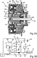
- a generally designated 10 arrangement is used for coupling an internal combustion engine 12 with an electric machine 14.
- the assembly 10 includes in particular a planetary gear with a sun gear 16, which carries a pulley 18. Der Sonnenrad 16 ist mit dem Clarrad 16 ownership.
- the pulley 18 is part of a belt drive 20 with a belt 22 and a pulley 24, which rotates with a rotor of the electric machine 14, not shown in the figure. Via the belt drive 20 is thus the electric machine 14 coupled to the sun gear 16.
- the planetary gear 10 further includes a plurality of planets 26, in this case, for example, four planets, which are coupled together via a planet carrier or web 28.
- the planet carrier comprises two parts, a part 28a coupled to the crankshaft 30 of the internal combustion engine 12, and the sun gear side second part 28b.
- the two parts 28a and 28b are connected to each other via the planet gears 26, namely in each case via a pin 32 penetrating them.
- the planetary gear further includes a ring gear 34.
- the sun gear 16 is coupled to an element 16 ', which rotates with it, and between the element 16' and the second part of the planet carrier 28b, a freewheel 36 is provided.
- the orientation of the freewheel 36 is such that the passage direction extends from the crankshaft 30 to the belt drive 20, that is, from the internal combustion engine 12 to the electric machine 14, whereas the electric machine 14 can overtake the internal combustion engine 12.
- a first clutch 38 is provided parallel to the freewheel 36, by which the crankshaft 30 can be coupled directly to the sun gear.
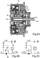
- the clutch 38 is realized such that a friction ring 40 is connected to the sun gear 16, see Fig. 1A , From a plate spring 42, a permanent magnetized disc 44 is pressed against the friction wheel 40. Under the action of a first electromagnet 46, the permanent magnetized disc 44 is pulled away from the friction disc 40 against the force of the disc spring 42 and the clutch is opened. In the ground state, with non-energized electromagnet 46, the clutch 38 is thus closed, see Fig. 1 B ,
- the ring gear 34 is designed to be axially displaceable in the present case. Integral with the ring gear is an armature 48, which extends over the same radial region as the friction plate 40 and the permanent magnetized disc 44. Thus, directly next to the electromagnet 46, a further electromagnet 50 may be provided, namely applied to a bobbin 52 additionally a second winding be, and this further permanent magnet can attract the armature 48 and thus hold the ring gear 46.
- a further electromagnet 50 may be provided, namely applied to a bobbin 52 additionally a second winding be, and this further permanent magnet can attract the armature 48 and thus hold the ring gear 46.
- a further electromagnet 50 may be provided, namely applied to a bobbin 52 additionally a second winding be, and this further permanent magnet can attract the armature 48 and thus hold the ring gear 46.
- a in the ground state - ie when not energized solenoid 50 - open clutch (or brake) 54 illustrate
- a damper arrangement 58 which comprises a directly with the crankshaft 30, ie on the side of the internal combustion engine before the planetary gear coupled support plate 60 which carries a rubber-elastic mass 62, which in turn holds a steel ring 64, which thus rotate with the support plate 60 can, but at the same time absorb and dampen vibrations.
- the compressor 66 for an air conditioning system of the motor vehicle which is part of the belt drive 22 via a belt pulley 68 and thus also the sun gear 16 is coupled to the electric machine 14.
- the air conditioning compressor 66 can therefore be operated both by the internal combustion engine 12 and by the electric machine 14.
- the clutch 38 can not always be closed immediately or opened immediately. Rather, the purpose of the clutch 38 is to then bypass the freewheel 36 when the freewheel would otherwise receive excessive dynamic loads or would operate excessively loud.
- the clutch 38 can be closed. There is thus a tachometer 70 for the rotational speed of the crankshaft 30.
- a tachometer 72 for the rotational speed of the crankshaft 30.
- the rotational speed of a rotor of the electric machine 14 or the pulley 24 is measured by a tachometer 72.
- the speed of the sun gear 16 can be derived by dividing by the gear ratio of the belt drive 20.
- a control device 74 which is adapted to energize the two electromagnets 46 and 50 and thus to open the clutch 38 or bring it to a close by deenergizing the electromagnet 46, and likewise to close the clutch 54 (by energizing the electromagnet 50) or to reopen (by deenergizing the solenoid 50).
- the controller 74 effects the manufacture of the below with reference to Fig. 2A to 5 shown operating conditions in the motor vehicle given the appropriate conditions for this.
- the power flow goes from the pulley 18 via the permanent magnetized disc 44 and a coupling piece 76 in the second part of the planet carrier 28b, via the planet 26 in the first part 28a of the planet carrier and thus in the crankshaft 30; because the freewheel 36 locks here.
- the electric machine 14 can therefore rotate much faster than the internal combustion engine 12, which is supposed to be put into rotation.
- the advantage is that because of the one-third of the speed, the applied torque is tripled. When starting the internal combustion engine but in particular a high torque is required.
- the ring gear does not rotate, so its speed n 2 is equal to 0.
- the power flow then passes through two parallel paths, namely firstly directly from the crankshaft 30 via the freewheel 36 in the parallel path is force on the first planet carrier member 28a, the planet 26 and the two planet carrier 28b, the coupling piece 76 and finally also on the permanent magnetized Transfer plate 44 to the pulley 18.
- the freewheel 36 is bridged.
- the electric machine can quickly bring the sun gear to a rotational speed which is the crankshaft 30, and the first clutch 38 can be closed for a short time.
- the described arrangement 10 thus makes it possible for the electric internal combustion engine to start with a ratio of 3: 1 and boost it with a ratio of 1: 1.
- the electric machine can be operated as a generator, which selectively rotates with a gear ratio of 1: 3 or 1: 1.
- the electric Machine carried out a stationary air conditioning with switched off internal combustion engine.
- the clutch 38 in particular the freewheel 36 is bridged and thus relieved, because the power flow is then not exclusively on the freewheel. This leads to less wear and less noise.
Landscapes
- Engineering & Computer Science (AREA)
- General Engineering & Computer Science (AREA)
- Mechanical Engineering (AREA)
- Physics & Mathematics (AREA)
- Electromagnetism (AREA)
- Structure Of Transmissions (AREA)
- Retarders (AREA)
- Pulleys (AREA)
Applications Claiming Priority (1)
| Application Number | Priority Date | Filing Date | Title |
|---|---|---|---|
| DE102011010086A DE102011010086A1 (de) | 2011-02-01 | 2011-02-01 | Anordnung mit einem Planetengetriebe für Kraftfahrzeug, Kraftfahrzeug sowie Verfahren zum Betreiben eines Planetengetriebes |
Publications (1)
| Publication Number | Publication Date |
|---|---|
| EP2481954A1 true EP2481954A1 (fr) | 2012-08-01 |
Family
ID=45606929
Family Applications (1)
| Application Number | Title | Priority Date | Filing Date |
|---|---|---|---|
| EP12000522A Withdrawn EP2481954A1 (fr) | 2011-02-01 | 2012-01-27 | Agencement doté d'un engrenage épicycloïdal pour véhicules automobiles, véhicule automobile ainsi que procédé de fonctionnement d'un engrenage épicycloïdal |
Country Status (4)
| Country | Link |
|---|---|
| US (1) | US8517889B2 (fr) |
| EP (1) | EP2481954A1 (fr) |
| CN (1) | CN102628400A (fr) |
| DE (1) | DE102011010086A1 (fr) |
Families Citing this family (18)
| Publication number | Priority date | Publication date | Assignee | Title |
|---|---|---|---|---|
| IT1395630B1 (it) * | 2009-09-10 | 2012-10-16 | Gea Niro Soavi S P A Ora Gea Mechanical Equipment Italia S P A | Omogeneizzatore ad alta pressione con riduttore epicicloidale |
| US9228640B2 (en) * | 2010-06-10 | 2016-01-05 | Irobot Corporation | Transmission assemblies |
| DE102012015863A1 (de) * | 2012-08-06 | 2014-05-15 | Getrag Getriebe- Und Zahnradfabrik Hermann Hagenmeyer Gmbh & Cie Kg | Stufengetriebe für ein Kraftfahrzeug |
| JP5920321B2 (ja) * | 2013-11-27 | 2016-05-18 | トヨタ自動車株式会社 | 電気自動車用トランスアクスル |
| DE102014201716A1 (de) * | 2014-01-31 | 2015-01-22 | Schaeffler Technologies Gmbh & Co. Kg | Antriebsanordnung für ein Nebenaggregat und Verfahren zum Betreiben der Antriebsanordnung |
| US10320722B2 (en) * | 2014-10-23 | 2019-06-11 | Level 3 Communications, Llc | Subscription/notification of a conference in a collaboration conferencing system |
| DE102015203194B4 (de) * | 2015-02-23 | 2018-08-16 | Schaeffler Technologies AG & Co. KG | Verfahren zum Schalten eines Schaltgetriebeabschnitts für ein Fahrzeug |
| DE102015103584B4 (de) * | 2015-03-11 | 2024-10-10 | Gkn Automotive Limited | Getriebeanordnung und Elektroantrieb mit einer solchen Getriebeanordnung |
| JP6344357B2 (ja) * | 2015-09-30 | 2018-06-20 | マツダ株式会社 | 遠心振子ダンパ付き動力伝達装置 |
| JP6344373B2 (ja) * | 2015-12-07 | 2018-06-20 | マツダ株式会社 | 遠心振子ダンパ付きパワートレインの制御装置 |
| JP6278046B2 (ja) * | 2016-01-06 | 2018-02-14 | マツダ株式会社 | 遠心振子ダンパ付きパワートレインの制御装置 |
| FR3049658B1 (fr) * | 2016-03-30 | 2020-12-18 | Renault Sas | Strategie de demarrage par temps froids avec alterno-demarreur |
| JP6361695B2 (ja) * | 2016-06-09 | 2018-07-25 | トヨタ自動車株式会社 | 駆動伝達装置 |
| FR3053394B1 (fr) * | 2016-06-30 | 2019-08-09 | Hutchinson | Poulie de decouplage a embrayage deporte |
| CN107191564A (zh) * | 2017-05-19 | 2017-09-22 | 重庆凯瑞电动汽车系统有限公司 | 适用于电动车的两档变速器 |
| US10955025B2 (en) * | 2018-05-31 | 2021-03-23 | GM Global Technology Operations LLC | Vehicle powertrain variable vibration absorber assembly |
| CN112204271B (zh) * | 2018-06-02 | 2023-09-26 | 有能沛思株式会社 | 电动汽车用二级变速器 |
| CN212695833U (zh) * | 2019-12-24 | 2021-03-12 | 熵零技术逻辑工程院集团股份有限公司 | 一种驱动机构 |
Citations (9)
| Publication number | Priority date | Publication date | Assignee | Title |
|---|---|---|---|---|
| JPS56148133U (fr) * | 1980-04-05 | 1981-11-07 | ||
| DE19941705A1 (de) | 1998-09-09 | 2000-03-16 | Luk Lamellen & Kupplungsbau | Antriebsstrang |
| DE19822426C2 (de) | 1998-05-19 | 2000-03-23 | Daimler Chrysler Ag | Antriebsvorrichtung für Nebenaggregate einer Hubkolbenbrennkraftmaschine |
| JP2004245316A (ja) * | 2003-02-13 | 2004-09-02 | Ntn Corp | 回転伝達機構 |
| EP1459931A1 (fr) * | 2003-03-18 | 2004-09-22 | Mitsubishi Denki Kabushiki Kaisha | Engrenage planétaire pour véhicule à moteur |
| EP1555456A2 (fr) * | 2004-01-16 | 2005-07-20 | LuK Lamellen und Kupplungsbau Beteiligungs KG | Commande d'un train épicycloidal à démarreur/générateur comme auxiliaire par commande de la vitesse du démarreur/générateur |
| EP1282772B1 (fr) | 2000-05-17 | 2006-04-12 | Tesma Motoren- und Getriebetechnik Ges.m.b.H. | Engrenage reducteur pour le demarreur-generateur d'un moteur a combustion interne |
| DE102006053139A1 (de) * | 2006-11-10 | 2008-05-15 | Compact Dynamics Gmbh | Antriebsvorrichtung mit einer elektrischen Maschine |
| WO2010144753A1 (fr) * | 2009-06-10 | 2010-12-16 | Czero, Inc. | Systèmes et procédés d'hybridation de véhicule motorisé utilisant des composants hydrauliques |
Family Cites Families (3)
| Publication number | Priority date | Publication date | Assignee | Title |
|---|---|---|---|---|
| GB1269457A (en) * | 1971-01-06 | 1972-04-06 | Praga Automobilove Zd Y Narodn | Four forward ratio and reverse ratio planetary change-speed gear device |
| JPS6448133U (fr) | 1987-09-18 | 1989-03-24 | ||
| CN2738458Y (zh) * | 2004-10-28 | 2005-11-02 | 李光宗 | 电机换向增矩轮毂 |
-
2011
- 2011-02-01 DE DE102011010086A patent/DE102011010086A1/de not_active Withdrawn
-
2012
- 2012-01-27 EP EP12000522A patent/EP2481954A1/fr not_active Withdrawn
- 2012-01-31 US US13/362,956 patent/US8517889B2/en not_active Expired - Fee Related
- 2012-02-01 CN CN2012100970121A patent/CN102628400A/zh not_active Withdrawn
Patent Citations (9)
| Publication number | Priority date | Publication date | Assignee | Title |
|---|---|---|---|---|
| JPS56148133U (fr) * | 1980-04-05 | 1981-11-07 | ||
| DE19822426C2 (de) | 1998-05-19 | 2000-03-23 | Daimler Chrysler Ag | Antriebsvorrichtung für Nebenaggregate einer Hubkolbenbrennkraftmaschine |
| DE19941705A1 (de) | 1998-09-09 | 2000-03-16 | Luk Lamellen & Kupplungsbau | Antriebsstrang |
| EP1282772B1 (fr) | 2000-05-17 | 2006-04-12 | Tesma Motoren- und Getriebetechnik Ges.m.b.H. | Engrenage reducteur pour le demarreur-generateur d'un moteur a combustion interne |
| JP2004245316A (ja) * | 2003-02-13 | 2004-09-02 | Ntn Corp | 回転伝達機構 |
| EP1459931A1 (fr) * | 2003-03-18 | 2004-09-22 | Mitsubishi Denki Kabushiki Kaisha | Engrenage planétaire pour véhicule à moteur |
| EP1555456A2 (fr) * | 2004-01-16 | 2005-07-20 | LuK Lamellen und Kupplungsbau Beteiligungs KG | Commande d'un train épicycloidal à démarreur/générateur comme auxiliaire par commande de la vitesse du démarreur/générateur |
| DE102006053139A1 (de) * | 2006-11-10 | 2008-05-15 | Compact Dynamics Gmbh | Antriebsvorrichtung mit einer elektrischen Maschine |
| WO2010144753A1 (fr) * | 2009-06-10 | 2010-12-16 | Czero, Inc. | Systèmes et procédés d'hybridation de véhicule motorisé utilisant des composants hydrauliques |
Also Published As
| Publication number | Publication date |
|---|---|
| US8517889B2 (en) | 2013-08-27 |
| US20130029804A1 (en) | 2013-01-31 |
| CN102628400A (zh) | 2012-08-08 |
| DE102011010086A1 (de) | 2012-08-02 |
Similar Documents
| Publication | Publication Date | Title |
|---|---|---|
| EP2481954A1 (fr) | Agencement doté d'un engrenage épicycloïdal pour véhicules automobiles, véhicule automobile ainsi que procédé de fonctionnement d'un engrenage épicycloïdal | |
| DE102014217455B4 (de) | Verfahren zum Starten eines Verbrennungsmotors durch einen riemengetriebenen Startergenerator | |
| DE102004033522A1 (de) | Nockenwellenversteller mit elektrischem Antrieb | |
| DE102010001259A1 (de) | Getriebeölpumpe für ein Automatgetriebe und Verfahren zum Betreiben der Getriebeölpumpe | |
| DE19931963A1 (de) | Antriebsvorrichtung | |
| WO2012031650A1 (fr) | Amortisseur électrique pour un véhicule à moteur | |
| WO2018192892A1 (fr) | Chaîne cinématique hybride pour un véhicule hybride | |
| DE19952625A1 (de) | Antriebssystem | |
| DE102010033364A1 (de) | Fahrzeugantrieb | |
| DE102014207720B4 (de) | Verfahren zur Steuerung eines Riementriebs für eine Brennkraftmaschine | |
| DE102015215965A1 (de) | Antriebseinrichtung für ein Kraftfahrzeug, insbesondere ein Elektrofahrzeug, sowie Verfahren zum Antreiben eines solchen Kraftfahrzeugs | |
| DE102007055706A1 (de) | Verfahren zum verschleißfreien Bremsen bei einem ein elektrodynamisches Antriebssystem aufweisenden Fahrzeug | |
| DE102007020867A1 (de) | Riementriebanordnung für Nebenaggregate eines Kraftfahrzeugmotors | |
| DE102014220926A1 (de) | Verfahren zum Regeln der Riemenspannung eines Riementriebes für eine Brennkraftmaschine | |
| DE3819986A1 (de) | Regelbarer antrieb und verfahren zu seiner steuerung | |
| DE102012218455A1 (de) | Spannvorrichtung für Zugmitteltrieb mit variabler Vorspannkraft und Verfahren zum Steuern desselben | |
| DE102017222711B4 (de) | Getriebe für ein Kraftfahrzeug | |
| EP2481955B1 (fr) | Agencement doté d'un moteur à combustion interne, d'une machine électrique et d'un engrenage épicycloïdal entre celui-ci | |
| DE102014200331A1 (de) | Ölpumpenantrieb mit schaltbarer Antriebsübersetzung | |
| DE102012217407A1 (de) | Ausgleichswelle | |
| DE102011087524A1 (de) | Riementrieb mit schaltbarem Planetengetriebe | |
| DE102011102798A1 (de) | Pumpenanordnung | |
| WO2010052047A1 (fr) | Agencement de démarreur avec entraînement par groupe auxiliaire | |
| DE3523999A1 (de) | Variable drehzahluebersetzungsvorrichtung fuer eine lichtmaschine eines kraftfahrzeugs | |
| EP3173663A1 (fr) | Boite de vitesses d'un vehicule automobile, et groupe motopropulseur pour un vehicule automobile equipe d'une telle boite de vitesses |
Legal Events
| Date | Code | Title | Description |
|---|---|---|---|
| PUAI | Public reference made under article 153(3) epc to a published international application that has entered the european phase |
Free format text: ORIGINAL CODE: 0009012 |
|
| AK | Designated contracting states |
Kind code of ref document: A1 Designated state(s): AL AT BE BG CH CY CZ DE DK EE ES FI FR GB GR HR HU IE IS IT LI LT LU LV MC MK MT NL NO PL PT RO RS SE SI SK SM TR |
|
| AX | Request for extension of the european patent |
Extension state: BA ME |
|
| 17P | Request for examination filed |
Effective date: 20130201 |
|
| 17Q | First examination report despatched |
Effective date: 20130725 |
|
| STAA | Information on the status of an ep patent application or granted ep patent |
Free format text: STATUS: THE APPLICATION HAS BEEN WITHDRAWN |
|
| 18W | Application withdrawn |
Effective date: 20140805 |