EP1556588B1 - Systeme de refroidissement d'un groupe motopropulseur, notament de vehicule automobile, comprenant un echangeur liquide/liquide - Google Patents
Systeme de refroidissement d'un groupe motopropulseur, notament de vehicule automobile, comprenant un echangeur liquide/liquide Download PDFInfo
- Publication number
- EP1556588B1 EP1556588B1 EP03782509A EP03782509A EP1556588B1 EP 1556588 B1 EP1556588 B1 EP 1556588B1 EP 03782509 A EP03782509 A EP 03782509A EP 03782509 A EP03782509 A EP 03782509A EP 1556588 B1 EP1556588 B1 EP 1556588B1
- Authority
- EP
- European Patent Office
- Prior art keywords
- cooling
- engine
- radiator
- loop
- secondary loop
- Prior art date
- Legal status (The legal status is an assumption and is not a legal conclusion. Google has not performed a legal analysis and makes no representation as to the accuracy of the status listed.)
- Expired - Lifetime
Links
- 238000001816 cooling Methods 0.000 title claims abstract description 47
- 239000007788 liquid Substances 0.000 title description 4
- 239000012809 cooling fluid Substances 0.000 claims description 22
- 239000003921 oil Substances 0.000 claims description 14
- 238000004378 air conditioning Methods 0.000 claims description 12
- 239000010705 motor oil Substances 0.000 claims description 4
- 238000002485 combustion reaction Methods 0.000 claims description 2
- 230000005540 biological transmission Effects 0.000 claims 1
- 239000007789 gas Substances 0.000 claims 1
- 239000012530 fluid Substances 0.000 abstract description 8
- 239000002826 coolant Substances 0.000 abstract 3
- 239000012080 ambient air Substances 0.000 abstract 1
- XLYOFNOQVPJJNP-UHFFFAOYSA-N water Substances O XLYOFNOQVPJJNP-UHFFFAOYSA-N 0.000 description 6
- 238000010438 heat treatment Methods 0.000 description 4
- 230000003247 decreasing effect Effects 0.000 description 2
- 239000013529 heat transfer fluid Substances 0.000 description 2
- 235000021183 entrée Nutrition 0.000 description 1
- 239000000446 fuel Substances 0.000 description 1
- 239000003507 refrigerant Substances 0.000 description 1
Images

Classifications
-
- F—MECHANICAL ENGINEERING; LIGHTING; HEATING; WEAPONS; BLASTING
- F01—MACHINES OR ENGINES IN GENERAL; ENGINE PLANTS IN GENERAL; STEAM ENGINES
- F01P—COOLING OF MACHINES OR ENGINES IN GENERAL; COOLING OF INTERNAL-COMBUSTION ENGINES
- F01P7/00—Controlling of coolant flow
- F01P7/14—Controlling of coolant flow the coolant being liquid
- F01P7/16—Controlling of coolant flow the coolant being liquid by thermostatic control
- F01P7/165—Controlling of coolant flow the coolant being liquid by thermostatic control characterised by systems with two or more loops
-
- F—MECHANICAL ENGINEERING; LIGHTING; HEATING; WEAPONS; BLASTING
- F01—MACHINES OR ENGINES IN GENERAL; ENGINE PLANTS IN GENERAL; STEAM ENGINES
- F01P—COOLING OF MACHINES OR ENGINES IN GENERAL; COOLING OF INTERNAL-COMBUSTION ENGINES
- F01P5/00—Pumping cooling-air or liquid coolants
- F01P5/10—Pumping liquid coolant; Arrangements of coolant pumps
- F01P2005/105—Using two or more pumps
-
- F—MECHANICAL ENGINEERING; LIGHTING; HEATING; WEAPONS; BLASTING
- F01—MACHINES OR ENGINES IN GENERAL; ENGINE PLANTS IN GENERAL; STEAM ENGINES
- F01P—COOLING OF MACHINES OR ENGINES IN GENERAL; COOLING OF INTERNAL-COMBUSTION ENGINES
- F01P5/00—Pumping cooling-air or liquid coolants
- F01P5/10—Pumping liquid coolant; Arrangements of coolant pumps
- F01P5/12—Pump-driving arrangements
- F01P2005/125—Driving auxiliary pumps electrically
-
- F—MECHANICAL ENGINEERING; LIGHTING; HEATING; WEAPONS; BLASTING
- F01—MACHINES OR ENGINES IN GENERAL; ENGINE PLANTS IN GENERAL; STEAM ENGINES
- F01P—COOLING OF MACHINES OR ENGINES IN GENERAL; COOLING OF INTERNAL-COMBUSTION ENGINES
- F01P2050/00—Applications
- F01P2050/02—Marine engines
- F01P2050/06—Marine engines using liquid-to-liquid heat exchangers
-
- F—MECHANICAL ENGINEERING; LIGHTING; HEATING; WEAPONS; BLASTING
- F01—MACHINES OR ENGINES IN GENERAL; ENGINE PLANTS IN GENERAL; STEAM ENGINES
- F01P—COOLING OF MACHINES OR ENGINES IN GENERAL; COOLING OF INTERNAL-COMBUSTION ENGINES
- F01P2060/00—Cooling circuits using auxiliaries
- F01P2060/02—Intercooler
-
- F—MECHANICAL ENGINEERING; LIGHTING; HEATING; WEAPONS; BLASTING
- F01—MACHINES OR ENGINES IN GENERAL; ENGINE PLANTS IN GENERAL; STEAM ENGINES
- F01P—COOLING OF MACHINES OR ENGINES IN GENERAL; COOLING OF INTERNAL-COMBUSTION ENGINES
- F01P2060/00—Cooling circuits using auxiliaries
- F01P2060/04—Lubricant cooler
-
- F—MECHANICAL ENGINEERING; LIGHTING; HEATING; WEAPONS; BLASTING
- F01—MACHINES OR ENGINES IN GENERAL; ENGINE PLANTS IN GENERAL; STEAM ENGINES
- F01P—COOLING OF MACHINES OR ENGINES IN GENERAL; COOLING OF INTERNAL-COMBUSTION ENGINES
- F01P2060/00—Cooling circuits using auxiliaries
- F01P2060/04—Lubricant cooler
- F01P2060/045—Lubricant cooler for transmissions
-
- F—MECHANICAL ENGINEERING; LIGHTING; HEATING; WEAPONS; BLASTING
- F01—MACHINES OR ENGINES IN GENERAL; ENGINE PLANTS IN GENERAL; STEAM ENGINES
- F01P—COOLING OF MACHINES OR ENGINES IN GENERAL; COOLING OF INTERNAL-COMBUSTION ENGINES
- F01P2060/00—Cooling circuits using auxiliaries
- F01P2060/08—Cabin heater
-
- F—MECHANICAL ENGINEERING; LIGHTING; HEATING; WEAPONS; BLASTING
- F01—MACHINES OR ENGINES IN GENERAL; ENGINE PLANTS IN GENERAL; STEAM ENGINES
- F01P—COOLING OF MACHINES OR ENGINES IN GENERAL; COOLING OF INTERNAL-COMBUSTION ENGINES
- F01P2060/00—Cooling circuits using auxiliaries
- F01P2060/14—Condenser
-
- F—MECHANICAL ENGINEERING; LIGHTING; HEATING; WEAPONS; BLASTING
- F01—MACHINES OR ENGINES IN GENERAL; ENGINE PLANTS IN GENERAL; STEAM ENGINES
- F01P—COOLING OF MACHINES OR ENGINES IN GENERAL; COOLING OF INTERNAL-COMBUSTION ENGINES
- F01P2060/00—Cooling circuits using auxiliaries
- F01P2060/16—Outlet manifold
Definitions
- the invention relates to a cooling system for a powertrain, in particular for a motor vehicle, comprising a motor, in particular a heat engine, cooled by a circulation of a cooling fluid and a cooling radiator cooled by an external atmospheric air circulation. .
- Engines, thermal or otherwise, of motor vehicles are usually cooled by means of a cooling radiator placed at the front of the vehicle and cooled by a flow of fresh air passing through it.
- a cooling circuit circulates a heat transfer fluid between the engine and the cooling radiator to cool the engine.
- motor vehicles include many equipment that exchange thermal energy with their external environment.
- This equipment is, for example, the condenser of the air conditioning circuit of the passenger compartment of the motor vehicle, a charge air radiator, a radiator for cooling the engine oil and / or the gearbox, or a radiator for cooling the fuel.
- the air conditioning circuit of the passenger compartment of the motor vehicle comprises a heat exchanger, constituting a condenser, disposed at the front of the vehicle, in front of the cooling radiator of the engine.
- a particular refrigerant separate from the heat transfer fluid of the engine, travels through the air conditioning circuit.
- Special pipes are needed to connect the condenser to the evaporator which is located in the housing of the air conditioning and heating unit of the passenger compartment of the vehicle.
- the cooling of the air is performed in an air-air heat exchanger which is arranged at the front of the vehicle and which is cooled by a circulation of air. atmospheric air.
- each exchanger is sized to provide sufficient cooling for its own critical point that does not necessarily correspond to the critical operating conditions of other exchangers.
- the air conditioning condenser and the charge air radiator do not operate at full speed necessarily at the same times.
- the exchangers penalize each other by decreasing the flow rate or the air velocity available for the other radiators.
- the air conditioning condenser placed in front of the engine cooling radiator, slows down the air flow, even when the air conditioning system is not in operation.
- the present invention relates to a cooling system of a powertrain as mentioned above which overcomes these disadvantages.
- the cooling system uses a unique cooling exchanger that exchanges with atmospheric air. Consequently, this radiator can be dimensioned widely and it is not penalized by the presence in front of or behind it of a number of secondary radiators of smaller size, such as the condenser of the air conditioning circuit, the air radiator of supercharger, oil cooler, etc.
- the equipment of the vehicle to be cooled is not cooled, as in the prior art, by means of special exchangers exchanging heat directly with the outside atmospheric air, but by an exchanger connected to the secondary loop and cooled by the circulation of the cooling fluid.
- said intermediate exchanger the heat exchange between the first and second fluid takes place, advantageously, directly, that is to say, without involving a third fluid.
- Said intermediate exchanger is thus crossed only by the cooling fluid of the loop primary and by the cooling fluid of the secondary loop.
- This cooling system consists of a primary loop designated by the general reference 2 and a secondary loop designated by the general reference 4.
- the primary loop includes the engine 10 of the vehicle and a water pump 12, usually a pump mechanical, which circulates a cooling fluid through the engine block in order to evacuate excess calories.
- a thermostatic housing 14 At the motor output, there is a thermostatic housing 14.
- the secondary loop 4 comprises a cooling radiator 18 traversed by an outside air flow and located at the front of the vehicle.
- the secondary loop further comprises a number of exchangers for cooling, possibly heating, various equipment of the motor vehicle.
- the cooling system comprises a charge air cooler 22 and a condenser 24.
- the charge air radiator 22 is intended to cool the air prior to admission into the combustion chambers of the engine. .
- the condenser 24 is part of the air conditioning circuit of the passenger compartment of the vehicle.
- a water pump 20, generally an electric pump, circulates the cooling fluid in the secondary loop 4. The same fluid flows in the primary loop 2 and the secondary loop 4.
- the primary loop and the secondary loop are in heat exchange relationship with each other by an intermediate heat exchanger 26 disposed between them.
- the engine cooling fluid after passing through the thermostatic housing 14, is conveyed via a pipe 30 to the intermediate heat exchanger 26. It emerges from the heat exchanger via a pipe 32 which returns it to the pump 12 and to the block motor 10.
- the cooling fluid leaving the charge air cooler 22 and the condenser 24 is led through a pipe 34 in the intermediate heat exchanger 26.
- the cooling fluid cools the cooling fluid of the primary loop.
- the cooling fluid of the secondary loop leaves the intermediate heat exchanger via a pipe 36 which returns it to the water pump 20, then through a pipe 38 to the cooling radiator 18 in which it is cooled again.
- the motor 10 is not cooled directly by heat exchange with the ambient atmospheric air, as is usually done, but by a liquid / liquid heat exchange in the intermediate exchanger 26. that the cooling radiator 18 is the only radiator of the cooling system of the invention.
- the exchangers 22 and 24 are respectively air-water and freon-water exchangers which are cooled by the cooling fluid flowing in the secondary loop.
- the radiator 18 serves both to cool the engine block 10, the charge air radiator 22 and the condenser 24. This greatly reduces the number of exchangers on the front of the vehicle compared to currently known systems. The system gains in simplicity and its size in the front face is decreased.
- the cooling system of the invention comprises a heater pipe 40 on which is mounted a heater 42 used for heating the passenger compartment of the vehicle.
- the pipe 40 is mounted parallel to the engine block.
- the thermostatic housing 14 circulates a fraction of the cooling fluid leaving the engine block 10 through the heater pipe 40.
- a cooling radiator 44 exhaust gas can be advantageously mounted on the duct heater 40.
- the system of the invention shown on the Figure 1 further comprises an oil radiator pipe 46 on which is mounted an oil radiator 48.
- the pipe 46 is connected to the thermostatic housing 14.
- the oil radiator is used to cool the gearbox oil or the oil cooler. engine, or both.
- the oil radiator 48 may be integrated in the intermediate heat exchanger 26. In this case, the oil radiator pipe 46 is eliminated.
- the exchanger 26 is then a multi-fluid and multi-temperature exchanger. In the same way, it is possible to move the thermal control system, in other words the thermostatic housing 14, on the intermediate heat exchanger 26.
- the cooling system comprises a bypass line 52 connected to the thermostatic housing 14 and which passes through an expansion tank 54. After passing through the expansion vessel, the cooling fluid returns to the water pump 12 without having been cooled.
- This bypass or short circuit also called bypass (bypass)
- bypass is used at low temperatures to promote the temperature rise of the engine.
- the secondary loop 4 also comprises a pipe 56 connected to the inlet of the radiator 18 and at the outlet of the intermediate exchanger 26, which passes through the expansion vessel 54, which is thus an expansion vessel common to the primary loop 2 and the secondary loop 4.
- the two loops do not are not isolated from one another and can communicate with one another via the expansion vessel 54.
- the cooling system of the Figure 2 is distinguished by the fact that it comprises a four-way distribution valve 60 located radiator output 18.
- the distribution valve 60 comprises an inlet channel through which the cold cooling fluid exiting the radiator 18 enters, and three outlets designated respectively by the references 60-1, 60-2 and 60-3.
- Channel 60-1 is connected to condenser 24, track 60-2 is connected to the charge air cooler 22 and track 60-3 is connected to a short-circuit line 62 which is not on the control system. the Figure 1 .
- the short-circuiting line 62 allows the cooling fluid of the secondary loop to avoid the exchangers 22 and 24 when this is not necessary. For example, at low engine power, it is not necessary to cool the air admitted to the engine chambers. Also, when the outside temperature is low, the air conditioning system of the cabin is not used. Thus, the entire cooling capacity of the radiator 18 is available for other functions, in particular for cooling the engine 10 of the vehicle.
Landscapes
- Engineering & Computer Science (AREA)
- Chemical & Material Sciences (AREA)
- Combustion & Propulsion (AREA)
- Mechanical Engineering (AREA)
- General Engineering & Computer Science (AREA)
- Cooling, Air Intake And Gas Exhaust, And Fuel Tank Arrangements In Propulsion Units (AREA)
- Motor Or Generator Cooling System (AREA)
- Electric Propulsion And Braking For Vehicles (AREA)
Description
- L'invention concerne un système de refroidissement d'un groupe motopropulseur, notamment de véhicule automobile, comprenant un moteur, notamment thermique, refroidi par une circulation d'un fluide de refroidissement et un radiateur de refroidissement refroidi par une circulation d'air atmosphérique extérieur.
- Les moteurs, thermiques ou autres, de véhicules automobiles sont refroidis habituellement au moyen d'un radiateur de refroidissement placé à l'avant du véhicule et refroidi par un flux d'air frais qui le traverse. Un circuit de refroidissement permet de faire circuler un fluide caloporteur entre le moteur et le radiateur de refroidissement pour refroidir le moteur.
- En outre, les véhicules automobiles comportent de nombreux équipements qui échangent de l'énergie thermique avec leur environnement extérieur. Ces équipements sont, par exemple, le condenseur du circuit de climatisation de l'habitacle du véhicule automobile, un radiateur d'air de suralimentation, un radiateur de refroidissement de l'huile du moteur et/ou de la boîte de vitesses, ou encore un radiateur de refroidissement du carburant.
- Dans les véhicules fabriqués actuellement, on prévoit un circuit de fluide spécial pour chaque équipement à refroidir ou à réchauffer. Par exemple, le circuit de climatisation de l'habitacle du véhicule automobile comporte un échangeur de chaleur, constituant un condenseur, disposé à l'avant du véhicule, devant le radiateur de refroidissement du moteur thermique. Un fluide frigorigène particulier, distinct du fluide caloporteur du moteur thermique, parcourt le circuit de climatisation. Des conduites spéciales sont nécessaires pour relier le condenseur à l'évaporateur qui est situé dans le boîtier de l'appareil de climatisation et de chauffage de l'habitacle du véhicule. De même, si le véhicule est équipé d'un refroidisseur d'air de suralimentation, le refroidissement de l'air est effectué dans un échangeur air-air qui est disposé à l'avant du véhicule et qui est refroidi par une circulation d'air atmosphérique.
- Cette conception se traduit par la présence d'un grand nombre d'échangeurs distincts en face avant du véhicule. Ces échangeurs occupent un espace important. En outre, les canalisations de raccordement augmentent encore le coût et l'encombrement de ces systèmes. De plus, chaque échangeur est dimensionné de manière à assurer un refroidissement suffisant pour son propre point critique qui ne correspond pas nécessairement aux conditions de fonctionnement critique des autres échangeurs.
- Par exemple, le condenseur du circuit de climatisation et le radiateur d'air de suralimentation ne fonctionnent pas à plein régime nécessairement aux mêmes instants. De ce fait, les échangeurs se pénalisent les uns les autres en diminuant le débit ou la vitesse de l'air disponible pour les autres radiateurs. Par exemple, le condenseur du circuit de climatisation, placé devant le radiateur de refroidissement du moteur, ralentit le débit de l'air, y compris lorsque le circuit de climatisation n'est pas en fonctionnement.
- Il est en outre connu du document
JP1155021 US 3080857A ) un système de refroidissement selon le préambule de la revendication 1. - La présente invention a pour objet un système de refroidissement d'un groupe motopropulseur tel qu'évoqué plus haut qui remédie à ces inconvénients.
- Ces buts sont atteints, conformément à l'invention, par les caractéristiques de la revendication 1.
- Par fluide « de même nature », on entend que les fluides ont sensiblement les mêmes caractéristiques physiques, notamment la même viscosité et/ou les mêmes points de changement d'état, voire la même composition.
- Grâce à cette caractéristique, le système de refroidissement utilise un échangeur de refroidissement unique échangeant avec l'air atmosphérique. En conséquence, ce radiateur peut être dimensionné largement et il n'est pas pénalisé par la présence devant ou derrière lui d'un certain nombre de radiateurs secondaires de plus petite dimension, comme le condenseur du circuit de climatisation, le radiateur d'air de suralimentation, le radiateur d'huile, etc.
- Les équipements du véhicule qui doivent être refroidis ne sont pas refroidis, comme dans l'art antérieur, au moyen d'échangeurs particuliers échangeant directement de la chaleur avec l'air atmosphérique extérieur, mais par un échangeur raccordé à la boucle secondaire et refroidi par la circulation du fluide de refroidissement.
- Dans ledit échangeur intermédiaire, l'échange thermique entre le premier et le second fluide a lieu, avantageusement, de façon directe, c'est-à-dire, sans faire intervenir de troisième fluide. Ledit échangeur intermédiaire est ainsi traversé uniquement par le fluide de refroidissement de la boucle primaire et par le fluide de refroidissement de la boucle secondaire.
- Des caractéristiques complémentaires et/ou alternatives de l'invention sont énumérées ci-après :
- le système de refroidissement comporte une branche d'aérotherme montée en parallèle entre la sortie du fluide de refroidissement et l'entrée du fluide de refroidissement dans le moteur thermique ;
- un échangeur de refroidissement des gaz d'échappement est monté sur la branche d'aérotherme ;
- le système de refroidissement comporte une branche de radiateur à huile sur laquelle est monté un radiateur de refroidissement de l'huile du moteur et/ou de la boîte de vitesses ;
- le système de refroidissement comporte un radiateur à huile de refroidissement de l'huile du moteur et/ou de la boîte de vitesses intégré au radiateur intermédiaire ;
- la boucle primaire et la boucle secondaire possèdent chacune une branche de vase d'expansion reliée à un vase d'expansion commun ;
- la boucle secondaire comporte un radiateur d'air de suralimentation ;
- la boucle secondaire comporte un condenseur faisant partie d'un circuit de climatisation de l'habitacle du véhicule ;
- il comporte une vanne de distribution à quatre voies, la vanne comportant une voie de sortie reliée au condenseur, une voie de sortie reliée au radiateur d'air de suralimentation et une voie reliée à une canalisation de court-circuit ;
- il comporte un boîtier thermostatique intégré à l'échangeur intermédiaire.
- D'autres caractéristiques et avantages de l'invention apparaîtront encore à la lecture de la description qui suit d'exemples de réalisation donnés à titre illustratif en référence aux figures annexées. Sur ces figures :
- la Figure 1illustre une première variante de réalisation d'un système de refroidissement conforme à la présente invention ; et
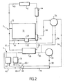
- la Figure 2illustre une seconde variante d'un système de refroidissement conforme à l'invention.
- On a représenté sur la
Figure 1 une vue d'ensemble d'un système de refroidissement d'un moteur thermique 10 de véhicule conforme à l'invention. Ce système de refroidissement est constitué d'une boucle primaire désignée par la référence générale 2 et d'une boucle secondaire désignée par la référence générale 4. La boucle primaire inclut le moteur thermique 10 du véhicule et une pompe à eau 12, généralement une pompe mécanique, qui fait circuler un fluide de refroidissement à travers le bloc du moteur afin d'évacuer les calories excédentaires. En sortie de moteur, on trouve un boîtier thermostatique 14. - La boucle secondaire 4 comprend un radiateur de refroidissement 18 traversé par un flux d'air extérieur et situé à l'avant du véhicule. La boucle secondaire comprend, en outre, un certain nombre d'échangeurs destinés à refroidir, éventuellement à réchauffer, divers équipements du véhicule automobile. Dans l'exemple représenté, le système de refroidissement comprend un radiateur d'air de suralimentation 22 et un condenseur 24. Le radiateur d'air de suralimentation 22 est destiné à refroidir l'air préalablement à son admission dans les chambres de combustion du moteur. Le condenseur 24 fait partie du circuit de climatisation de l'habitacle du véhicule. Une pompe à eau 20, généralement une pompe électrique, met en circulation le fluide de refroidissement dans la boucle secondaire 4. Le même fluide circule dans la boucle primaire 2 et la boucle secondaire 4.
- La boucle primaire et la boucle secondaire sont en relation d'échange thermique l'une avec l'autre par un échangeur de chaleur intermédiaire 26 disposé entre elles. Le fluide de refroidissement du moteur, après avoir traversé le boîtier thermostatique 14, est acheminé par une canalisation 30 jusqu'à l'échangeur intermédiaire 26. Il ressort de l'échangeur par une canalisation 32 qui le ramène à la pompe 12 et au bloc moteur 10.
- De la même manière, le fluide de refroidissement qui sort du refroidisseur d'air de suralimentation 22 et du condenseur 24 est conduit par une canalisation 34 dans l'échangeur intermédiaire 26. Dans cet échangeur, le fluide de refroidissement refroidit le fluide de refroidissement de la boucle primaire. Ensuite, le fluide de refroidissement de la boucle secondaire quitte l'échangeur intermédiaire par une canalisation 36 qui le ramène à la pompe à eau 20, puis, par une canalisation 38, au radiateur de refroidissement 18 dans lequel il est à nouveau refroidi.
- Ainsi, le moteur 10 n'est pas refroidi directement par échange de chaleur avec l'air atmosphérique ambiant, comme cela se fait habituellement, mais par un échange de chaleur liquide/liquide dans l'échangeur intermédiaire 26. On constate, en outre, que le radiateur de refroidissement 18 est l'unique radiateur du système de refroidissement de l'invention. Les échangeurs 22 et 24 sont respectivement des échangeurs air-eau et fréon-eau qui sont refroidis par le fluide de refroidissement qui circule dans la boucle secondaire.
- Ainsi, le radiateur 18 sert à la fois au refroidissement du bloc moteur 10, du radiateur d'air de suralimentation 22 et du condenseur 24. On réduit ainsi fortement le nombre d'échangeurs en face avant du véhicule par rapport aux systèmes actuellement connus. Le système gagne en simplicité et son encombrement en face avant est diminué.
- Le système de refroidissement de l'invention comporte une canalisation d'aérotherme 40 sur laquelle est monté un aérotherme 42 utilisé pour le chauffage de l'habitacle du véhicule. La canalisation 40 est montée parallèlement au bloc moteur. Lorsque le chauffage de l'habitacle est souhaité, par exemple par basse température extérieure, le boîtier thermostatique 14 fait circuler une fraction du fluide de refroidissement sortant du bloc moteur 10 par la canalisation d'aérotherme 40. En outre, un radiateur 44 de refroidissement des gaz d'échappement peut être avantageusement monté sur la canalisation d'aérotherme 40.
- Le système de l'invention représenté sur la
Figure 1 comporte, en outre, une canalisation 46 de radiateur à huile sur laquelle est monté un radiateur à huile 48. La canalisation 46 est raccordée au boîtier thermostatique 14. Le radiateur à huile est utilisé pour refroidir l'huile de la boîte de vitesses ou celle du moteur, voire les deux. En variante de réalisation, le radiateur à huile 48 peut être intégré à l'échangeur intermédiaire 26. Dans ce cas, la canalisation 46 de radiateur à huile est supprimée. L'échangeur 26 est alors un échangeur multi-fluides et multi-températures. De la même manière, il est possible de déplacer le système de régulation thermique, en d'autres termes le boîtier thermostatique 14, sur l'échangeur intermédiaire 26. - Enfin, le système de refroidissement comporte une canalisation de dérivation 52 raccordée au boîtier thermostatique 14 et qui transite par un vase d'expansion 54. Après avoir traversé le vase d'expansion, le fluide de refroidissement retourne vers la pompe à eau 12 sans avoir été refroidi. Cette canalisation de dérivation ou de court-circuit, encore appelée bipasse («by-pass»), est utilisée à basse température pour favoriser la montée en température du moteur. La boucle secondaire 4 comporte également une canalisation 56 raccordée à l'entrée du radiateur 18 et à la sortie de l'échangeur intermédiaire 26, qui transite par le vase d'expansion 54, qui est ainsi un vase d'expansion commun à la boucle primaire 2 et à la boucle secondaire 4. Ainsi, les deux boucles ne sont pas isolées l'une de l'autre et peuvent communiquer entre elles par l'intermédiaire du vase d'expansion 54.
- On a représenté sur la
Figure 2 une variante de réalisation du système de refroidissement de laFigure 1 . Sur laFigure 2 , les mêmes chiffres de référence désignent les mêmes éléments de la boucle primaire 2 et de la boucle secondaire 4. Le système de refroidissement de laFigure 2 se distingue par le fait qu'il comporte une vanne de distribution à quatre voies 60 située en sortie de radiateur 18. - La vanne de distribution 60 comporte une voie d'entrée par laquelle le fluide de refroidissement froid sortant du radiateur 18 pénètre, et trois sorties désignées respectivement par les références 60-1, 60-2 et 60-3. La voie 60-1 est reliée au condenseur 24, la voie 60-2 est reliée au radiateur d'air de suralimentation 22 et la voie 60-3 est reliée à une canalisation de court-circuit 62 qui ne figure pas sur le système de la
Figure 1 . - La canalisation de court-circuit 62 permet au fluide de refroidissement de la boucle secondaire d'éviter les échangeurs 22 et 24 lorsque cela n'est pas nécessaire. Par exemple, à faible puissance du moteur, il n'est pas nécessaire de refroidir l'air admis dans les chambres du moteur. Egalement, lorsque la température extérieure est basse, le système de climatisation de l'habitacle n'est pas utilisé. Ainsi, la totalité de la capacité de refroidissement du radiateur 18 est disponible pour d'autres fonctions, notamment pour le refroidissement du moteur 10 du véhicule.
Claims (9)
- Système de refroidissement d'un groupe motopropulseur, notamment de véhicule automobile, comprenant un moteur (10), notamment thermique, refroidi par une circulation d'un fluide de refroidissement, et un radiateur de refroidissement (18) refroidi par une circulation d'air atmosphérique extérieur, le moteur (10) faisant partie d'une boucle primaire (2) et le radiateur de refroidissement (18) faisant partie d'une boucle secondaire (4), lesdites boucles primaires et secondaires étant aptes à autoriser une circulation indépendante d'un premier et d'un second fluide de refroidissement, de même nature, la boucle primaire (2) et la boucle secondaire (4) étant en relation d'échange thermique l'une avec l'autre par l'intermédiaire d'un échangeur intermédiaire (26) traversé à la fois par le fluide de refroidissement de la boucle primaire (2) et par le fluide de refroidissement de la boucle secondaire (4) caractérisé en ce qu'il comporte une branche d'aérotherme (40) montée en parallèle entre la sortie et l'entrée du bloc moteur (10) comportant un aérotherme (42).
- Système selon la revendication 1, caractérisé en ce qu'un échangeur (44) de refroidissement des gaz d'échappement est monté sur la branche d'aérotherme (40).
- Système selon l'une des revendications 1 à 2, caractérisé en ce qu'il comporte une branche de radiateur à huile (46) sur laquelle est monté un radiateur à huile (48) de refroidissement de l'huile du moteur et/ou de la boîte de vitesses.
- Système selon l'une des revendications 1 à 2, caractérisé en ce qu'il comporte un radiateur à huile intégré à l'échangeur intermédiaire (26).
- Système selon l'une des revendications 1 à 4, caractérisé en ce que la boucle primaire (2) et la boucle secondaire (4) possèdent chacune une branche de vase d'expansion (52, 56) reliée à un vase d'expansion commun (54).
- Système selon l'une des revendications 1 à 5, caractérisé en ce que la boucle secondaire (4) comporte un radiateur d'air de suralimentation (22).
- Système selon l'une des revendications 1 à 6, caractérisé en ce que la boucle secondaire (4) comporte un condenseur (24) faisant partie d'un circuit de climatisation de l'habitacle du véhicule.
- Système selon les revendications 6 et 7, caractérisé en ce qu'il comporte une vanne de distribution (60) à quatre voies, la vanne (60) comportant une voie de sortie (60-1) reliée au condenseur (24), une voie de sortie (60-2) reliée au radiateur d'air de suralimentation (22) et une voie (60-3) reliée à une canalisation de court-circuit (62).
- Système selon l'une des revendications 1 à 8, caractérisé en ce qu'il comporte un boîtier thermostatique intégré à l'échangeur intermédiaire (26).
Applications Claiming Priority (3)
| Application Number | Priority Date | Filing Date | Title |
|---|---|---|---|
| FR0213539A FR2846368B1 (fr) | 2002-10-29 | 2002-10-29 | Systeme de refroidissement d'un moteur thermique de vehicule automobile comprenant un echangeur liquide/liquide |
| FR0213539 | 2002-10-29 | ||
| PCT/FR2003/003195 WO2004040105A1 (fr) | 2002-10-29 | 2003-10-28 | Systeme de refroidissement d'un groupe motopropulseur, notament de vehicule automobile, comprenant un echangeur liquide/liquide |
Publications (2)
| Publication Number | Publication Date |
|---|---|
| EP1556588A1 EP1556588A1 (fr) | 2005-07-27 |
| EP1556588B1 true EP1556588B1 (fr) | 2012-01-18 |
Family
ID=32088390
Family Applications (1)
| Application Number | Title | Priority Date | Filing Date |
|---|---|---|---|
| EP03782509A Expired - Lifetime EP1556588B1 (fr) | 2002-10-29 | 2003-10-28 | Systeme de refroidissement d'un groupe motopropulseur, notament de vehicule automobile, comprenant un echangeur liquide/liquide |
Country Status (5)
| Country | Link |
|---|---|
| EP (1) | EP1556588B1 (fr) |
| AT (1) | ATE542034T1 (fr) |
| AU (1) | AU2003290146A1 (fr) |
| FR (1) | FR2846368B1 (fr) |
| WO (1) | WO2004040105A1 (fr) |
Families Citing this family (5)
| Publication number | Priority date | Publication date | Assignee | Title |
|---|---|---|---|---|
| GB2420175B (en) * | 2004-11-10 | 2009-10-28 | Agco Gmbh & Co | Cooling system for farming tractors |
| RU2293190C1 (ru) * | 2005-09-28 | 2007-02-10 | Федеральное государственное унитарное предприятие Всероссийский научно-исследовательский и конструкторско-технологический институт подвижного состава Министерства путей сообщения Российской Федерации (ФГУП ВНИКТИ МПС России) | Объединенная система охлаждения двигателя внутреннего сгорания и его наддувочного воздуха |
| DE102010039810A1 (de) * | 2010-08-26 | 2012-03-01 | Behr Gmbh & Co. Kg | Kühlsystem und Kühlverfahren für ein Fahrzeug |
| DE102012223069A1 (de) * | 2012-12-13 | 2014-06-18 | Bayerische Motoren Werke Aktiengesellschaft | Kühlmittelkreislauf für eine Brennkraftmaschine |
| SE1851252A1 (en) * | 2018-10-12 | 2019-09-13 | Scania Cv Ab | Cooling system and method for controlling temperature of coolant |
Family Cites Families (7)
| Publication number | Priority date | Publication date | Assignee | Title |
|---|---|---|---|---|
| DE384738C (de) * | 1923-11-05 | Norddeutsche Kuehlerfabrik G M | Einrichtung zur Regelung der Temperatur des Kuehlwassers von Automobilmotoren | |
| FR728749A (fr) * | 1931-12-23 | 1932-07-11 | Expl Des App Rotor Sa D | Procédé et dispositif de refroidissement des moteurs |
| DE1128702B (de) * | 1959-03-26 | 1962-04-26 | Sueddeutsche Kuehler Behr | Fluessigkeits-Kuehlanlage fuer Brennkraftmaschinen mit Aufladung |
| US3080857A (en) * | 1960-12-14 | 1963-03-12 | Int Harvester Co | Engine coolant system |
| JPH0742856B2 (ja) * | 1987-12-11 | 1995-05-15 | 株式会社クボタ | 水冷エンジンの排熱回収装置 |
| SE514537C2 (sv) * | 1998-11-12 | 2001-03-12 | Volvo Ab | Förbränningsmotorinstallation i ett motorfordon |
| IT1308421B1 (it) * | 1999-03-11 | 2001-12-17 | Fiat Ricerche | Sistema di raffreddamento per un motore a combustione interna. |
-
2002
- 2002-10-29 FR FR0213539A patent/FR2846368B1/fr not_active Expired - Fee Related
-
2003
- 2003-10-28 AT AT03782509T patent/ATE542034T1/de active
- 2003-10-28 WO PCT/FR2003/003195 patent/WO2004040105A1/fr not_active Ceased
- 2003-10-28 EP EP03782509A patent/EP1556588B1/fr not_active Expired - Lifetime
- 2003-10-28 AU AU2003290146A patent/AU2003290146A1/en not_active Abandoned
Also Published As
| Publication number | Publication date |
|---|---|
| EP1556588A1 (fr) | 2005-07-27 |
| FR2846368A1 (fr) | 2004-04-30 |
| ATE542034T1 (de) | 2012-02-15 |
| AU2003290146A1 (en) | 2004-05-25 |
| WO2004040105A1 (fr) | 2004-05-13 |
| FR2846368B1 (fr) | 2007-02-09 |
Similar Documents
| Publication | Publication Date | Title |
|---|---|---|
| US7168398B2 (en) | System for managing the heat energy produced by a motor vehicle heat engine | |
| US6230668B1 (en) | Locomotive cooling system | |
| AU2008305323B2 (en) | System and method for providing an integrated cooling system using an independent multi-control system | |
| EP1620637B1 (fr) | Systeme de refroidissement a basse temperature d'un equipement, notamment d'un equipement de vehicule automobile, et echangeurs de chaleur associes | |
| EP1282535B1 (fr) | Procede et dispositif de regulation thermique d'un habitacle de vehicule automobile | |
| EP3564504B1 (fr) | Systeme de refroidissement d'un moteur avec deux thermostats et integrant un circuit selon un cycle de rankine | |
| FR2832186A1 (fr) | Systeme de gestion de l'energie thermique d'un moteur thermique comprenant deux reseaux | |
| EP2102575A1 (fr) | Echangeur de chaleur comprenant au moins trois parties d'echanges de chaleur et systeme de gestion de l'energie thermique comportant un tel echangeur | |
| FR3093766A1 (fr) | Système de conditionnement d’air équipé d’un système de gestion thermique d’huile et d’air pressurisé | |
| FR3036135A1 (fr) | Circuit de refroidissement d’un moteur | |
| EP1966473B1 (fr) | Dispositif de gestion thermique pour vehicule automobile | |
| EP4127431B1 (fr) | Dispositif de gestion thermique pour un véhicule automobile hybride | |
| WO2004040105A1 (fr) | Systeme de refroidissement d'un groupe motopropulseur, notament de vehicule automobile, comprenant un echangeur liquide/liquide | |
| FR2976322A1 (fr) | Repartiteur d'air comprenant un dispositif adapte a echanger de la chaleur avec de l'air de suralimentation, et systeme de transfert thermique comprenant un tel repartiteur | |
| FR2610989A1 (fr) | Circuit de refroidissement auxiliaire pour vehicule automobile | |
| FR2832185A1 (fr) | Systeme de gestion de l'energie thermique developpee par un moteur thermique de vehicule automobile | |
| FR2988467A1 (fr) | Installation de chauffage pour un vehicule hybride | |
| EP1963657A1 (fr) | Dispositif de refroidissement de l'air d'admission et des gaz d'echappement recircules | |
| EP1819910B1 (fr) | Systeme de refroidissement a basse temperature d'un equipement, notamment d'un equipement de vehicule automobile, et echangeurs de chaleur associes | |
| EP2061959B1 (fr) | Systeme de refroidissement d'un groupe motopropulseur de vehicule automobile, et procede de commande d'un tel systeme | |
| EP3680468B1 (fr) | Système d'échangeur thermique à trois voies pour unité d'alimentation auxiliaire | |
| FR2761405A1 (fr) | Circuit de refroidissement pour condenseur de climatisation de vehicule | |
| FR3144548A1 (fr) | Système de gestion thermique pour véhicule | |
| EP0992377A1 (fr) | Dispositif thermostatique de récupération de la chaleur des gaz d'échappement d'un véhicule | |
| FR2458412A1 (fr) | Dispositif de chauffage pour vehicule a moteur thermique, a refroidissement par air notamment |
Legal Events
| Date | Code | Title | Description |
|---|---|---|---|
| PUAI | Public reference made under article 153(3) epc to a published international application that has entered the european phase |
Free format text: ORIGINAL CODE: 0009012 |
|
| 17P | Request for examination filed |
Effective date: 20050317 |
|
| AK | Designated contracting states |
Kind code of ref document: A1 Designated state(s): AT BE BG CH CY CZ DE DK EE ES FI FR GB GR HU IE IT LI LU MC NL PT RO SE SI SK TR |
|
| AX | Request for extension of the european patent |
Extension state: AL LT LV MK |
|
| DAX | Request for extension of the european patent (deleted) | ||
| RAP1 | Party data changed (applicant data changed or rights of an application transferred) |
Owner name: VALEO SYSTEMES THERMIQUES |
|
| 17Q | First examination report despatched |
Effective date: 20110203 |
|
| GRAP | Despatch of communication of intention to grant a patent |
Free format text: ORIGINAL CODE: EPIDOSNIGR1 |
|
| GRAS | Grant fee paid |
Free format text: ORIGINAL CODE: EPIDOSNIGR3 |
|
| GRAA | (expected) grant |
Free format text: ORIGINAL CODE: 0009210 |
|
| AK | Designated contracting states |
Kind code of ref document: B1 Designated state(s): AT BE BG CH CY CZ DE DK EE ES FI FR GB GR HU IE IT LI LU MC NL PT RO SE SI SK TR |
|
| REG | Reference to a national code |
Ref country code: GB Ref legal event code: FG4D Free format text: NOT ENGLISH |
|
| REG | Reference to a national code |
Ref country code: CH Ref legal event code: EP |
|
| REG | Reference to a national code |
Ref country code: IE Ref legal event code: FG4D Free format text: LANGUAGE OF EP DOCUMENT: FRENCH Ref country code: AT Ref legal event code: REF Ref document number: 542034 Country of ref document: AT Kind code of ref document: T Effective date: 20120215 |
|
| REG | Reference to a national code |
Ref country code: DE Ref legal event code: R096 Ref document number: 60339782 Country of ref document: DE Effective date: 20120315 |
|
| REG | Reference to a national code |
Ref country code: NL Ref legal event code: VDEP Effective date: 20120118 |
|
| PG25 | Lapsed in a contracting state [announced via postgrant information from national office to epo] |
Ref country code: BG Free format text: LAPSE BECAUSE OF FAILURE TO SUBMIT A TRANSLATION OF THE DESCRIPTION OR TO PAY THE FEE WITHIN THE PRESCRIBED TIME-LIMIT Effective date: 20120418 Ref country code: NL Free format text: LAPSE BECAUSE OF FAILURE TO SUBMIT A TRANSLATION OF THE DESCRIPTION OR TO PAY THE FEE WITHIN THE PRESCRIBED TIME-LIMIT Effective date: 20120118 |
|
| REG | Reference to a national code |
Ref country code: IE Ref legal event code: FD4D |
|
| PG25 | Lapsed in a contracting state [announced via postgrant information from national office to epo] |
Ref country code: FI Free format text: LAPSE BECAUSE OF FAILURE TO SUBMIT A TRANSLATION OF THE DESCRIPTION OR TO PAY THE FEE WITHIN THE PRESCRIBED TIME-LIMIT Effective date: 20120118 Ref country code: GR Free format text: LAPSE BECAUSE OF FAILURE TO SUBMIT A TRANSLATION OF THE DESCRIPTION OR TO PAY THE FEE WITHIN THE PRESCRIBED TIME-LIMIT Effective date: 20120419 Ref country code: PT Free format text: LAPSE BECAUSE OF FAILURE TO SUBMIT A TRANSLATION OF THE DESCRIPTION OR TO PAY THE FEE WITHIN THE PRESCRIBED TIME-LIMIT Effective date: 20120518 |
|
| REG | Reference to a national code |
Ref country code: AT Ref legal event code: MK05 Ref document number: 542034 Country of ref document: AT Kind code of ref document: T Effective date: 20120118 |
|
| PG25 | Lapsed in a contracting state [announced via postgrant information from national office to epo] |
Ref country code: CY Free format text: LAPSE BECAUSE OF FAILURE TO SUBMIT A TRANSLATION OF THE DESCRIPTION OR TO PAY THE FEE WITHIN THE PRESCRIBED TIME-LIMIT Effective date: 20120118 |
|
| PG25 | Lapsed in a contracting state [announced via postgrant information from national office to epo] |
Ref country code: EE Free format text: LAPSE BECAUSE OF FAILURE TO SUBMIT A TRANSLATION OF THE DESCRIPTION OR TO PAY THE FEE WITHIN THE PRESCRIBED TIME-LIMIT Effective date: 20120118 Ref country code: SI Free format text: LAPSE BECAUSE OF FAILURE TO SUBMIT A TRANSLATION OF THE DESCRIPTION OR TO PAY THE FEE WITHIN THE PRESCRIBED TIME-LIMIT Effective date: 20120118 Ref country code: IE Free format text: LAPSE BECAUSE OF FAILURE TO SUBMIT A TRANSLATION OF THE DESCRIPTION OR TO PAY THE FEE WITHIN THE PRESCRIBED TIME-LIMIT Effective date: 20120118 Ref country code: SE Free format text: LAPSE BECAUSE OF FAILURE TO SUBMIT A TRANSLATION OF THE DESCRIPTION OR TO PAY THE FEE WITHIN THE PRESCRIBED TIME-LIMIT Effective date: 20120118 Ref country code: DK Free format text: LAPSE BECAUSE OF FAILURE TO SUBMIT A TRANSLATION OF THE DESCRIPTION OR TO PAY THE FEE WITHIN THE PRESCRIBED TIME-LIMIT Effective date: 20120118 Ref country code: RO Free format text: LAPSE BECAUSE OF FAILURE TO SUBMIT A TRANSLATION OF THE DESCRIPTION OR TO PAY THE FEE WITHIN THE PRESCRIBED TIME-LIMIT Effective date: 20120118 Ref country code: CZ Free format text: LAPSE BECAUSE OF FAILURE TO SUBMIT A TRANSLATION OF THE DESCRIPTION OR TO PAY THE FEE WITHIN THE PRESCRIBED TIME-LIMIT Effective date: 20120118 |
|
| PLBE | No opposition filed within time limit |
Free format text: ORIGINAL CODE: 0009261 |
|
| STAA | Information on the status of an ep patent application or granted ep patent |
Free format text: STATUS: NO OPPOSITION FILED WITHIN TIME LIMIT |
|
| PG25 | Lapsed in a contracting state [announced via postgrant information from national office to epo] |
Ref country code: IT Free format text: LAPSE BECAUSE OF FAILURE TO SUBMIT A TRANSLATION OF THE DESCRIPTION OR TO PAY THE FEE WITHIN THE PRESCRIBED TIME-LIMIT Effective date: 20120118 Ref country code: SK Free format text: LAPSE BECAUSE OF FAILURE TO SUBMIT A TRANSLATION OF THE DESCRIPTION OR TO PAY THE FEE WITHIN THE PRESCRIBED TIME-LIMIT Effective date: 20120118 |
|
| 26N | No opposition filed |
Effective date: 20121019 |
|
| PG25 | Lapsed in a contracting state [announced via postgrant information from national office to epo] |
Ref country code: AT Free format text: LAPSE BECAUSE OF FAILURE TO SUBMIT A TRANSLATION OF THE DESCRIPTION OR TO PAY THE FEE WITHIN THE PRESCRIBED TIME-LIMIT Effective date: 20120118 |
|
| REG | Reference to a national code |
Ref country code: DE Ref legal event code: R097 Ref document number: 60339782 Country of ref document: DE Effective date: 20121019 |
|
| BERE | Be: lapsed |
Owner name: VALEO SYSTEMES THERMIQUES Effective date: 20121031 |
|
| PG25 | Lapsed in a contracting state [announced via postgrant information from national office to epo] |
Ref country code: ES Free format text: LAPSE BECAUSE OF FAILURE TO SUBMIT A TRANSLATION OF THE DESCRIPTION OR TO PAY THE FEE WITHIN THE PRESCRIBED TIME-LIMIT Effective date: 20120429 |
|
| PG25 | Lapsed in a contracting state [announced via postgrant information from national office to epo] |
Ref country code: MC Free format text: LAPSE BECAUSE OF NON-PAYMENT OF DUE FEES Effective date: 20121031 |
|
| REG | Reference to a national code |
Ref country code: CH Ref legal event code: PL |
|
| GBPC | Gb: european patent ceased through non-payment of renewal fee |
Effective date: 20121028 |
|
| PG25 | Lapsed in a contracting state [announced via postgrant information from national office to epo] |
Ref country code: GB Free format text: LAPSE BECAUSE OF NON-PAYMENT OF DUE FEES Effective date: 20121028 Ref country code: BE Free format text: LAPSE BECAUSE OF NON-PAYMENT OF DUE FEES Effective date: 20121031 Ref country code: CH Free format text: LAPSE BECAUSE OF NON-PAYMENT OF DUE FEES Effective date: 20121031 Ref country code: LI Free format text: LAPSE BECAUSE OF NON-PAYMENT OF DUE FEES Effective date: 20121031 |
|
| PG25 | Lapsed in a contracting state [announced via postgrant information from national office to epo] |
Ref country code: TR Free format text: LAPSE BECAUSE OF FAILURE TO SUBMIT A TRANSLATION OF THE DESCRIPTION OR TO PAY THE FEE WITHIN THE PRESCRIBED TIME-LIMIT Effective date: 20120118 |
|
| PG25 | Lapsed in a contracting state [announced via postgrant information from national office to epo] |
Ref country code: LU Free format text: LAPSE BECAUSE OF NON-PAYMENT OF DUE FEES Effective date: 20121028 |
|
| PG25 | Lapsed in a contracting state [announced via postgrant information from national office to epo] |
Ref country code: HU Free format text: LAPSE BECAUSE OF FAILURE TO SUBMIT A TRANSLATION OF THE DESCRIPTION OR TO PAY THE FEE WITHIN THE PRESCRIBED TIME-LIMIT Effective date: 20031028 |
|
| REG | Reference to a national code |
Ref country code: FR Ref legal event code: PLFP Year of fee payment: 13 |
|
| REG | Reference to a national code |
Ref country code: FR Ref legal event code: PLFP Year of fee payment: 14 |
|
| REG | Reference to a national code |
Ref country code: FR Ref legal event code: PLFP Year of fee payment: 15 |
|
| REG | Reference to a national code |
Ref country code: FR Ref legal event code: PLFP Year of fee payment: 16 |
|
| PGFP | Annual fee paid to national office [announced via postgrant information from national office to epo] |
Ref country code: FR Payment date: 20201030 Year of fee payment: 18 Ref country code: DE Payment date: 20201009 Year of fee payment: 18 |
|
| REG | Reference to a national code |
Ref country code: DE Ref legal event code: R119 Ref document number: 60339782 Country of ref document: DE |
|
| PG25 | Lapsed in a contracting state [announced via postgrant information from national office to epo] |
Ref country code: DE Free format text: LAPSE BECAUSE OF NON-PAYMENT OF DUE FEES Effective date: 20220503 |
|
| PG25 | Lapsed in a contracting state [announced via postgrant information from national office to epo] |
Ref country code: FR Free format text: LAPSE BECAUSE OF NON-PAYMENT OF DUE FEES Effective date: 20211031 |