EP1556599B1 - Ensemble bride de carter - Google Patents
Ensemble bride de carter Download PDFInfo
- Publication number
- EP1556599B1 EP1556599B1 EP03773455A EP03773455A EP1556599B1 EP 1556599 B1 EP1556599 B1 EP 1556599B1 EP 03773455 A EP03773455 A EP 03773455A EP 03773455 A EP03773455 A EP 03773455A EP 1556599 B1 EP1556599 B1 EP 1556599B1
- Authority
- EP
- European Patent Office
- Prior art keywords
- housing flange
- bearing
- valve shaft
- flap
- gas cooler
- Prior art date
- Legal status (The legal status is an assumption and is not a legal conclusion. Google has not performed a legal analysis and makes no representation as to the accuracy of the status listed.)
- Expired - Lifetime
Links
- 239000007789 gas Substances 0.000 claims description 27
- 238000007789 sealing Methods 0.000 claims description 4
- 238000003466 welding Methods 0.000 claims description 4
- 238000010276 construction Methods 0.000 description 1
- 239000000498 cooling water Substances 0.000 description 1
- 239000003344 environmental pollutant Substances 0.000 description 1
- 239000002184 metal Substances 0.000 description 1
- 231100000719 pollutant Toxicity 0.000 description 1
- 239000011343 solid material Substances 0.000 description 1
Images

Classifications
-
- F—MECHANICAL ENGINEERING; LIGHTING; HEATING; WEAPONS; BLASTING
- F02—COMBUSTION ENGINES; HOT-GAS OR COMBUSTION-PRODUCT ENGINE PLANTS
- F02D—CONTROLLING COMBUSTION ENGINES
- F02D9/00—Controlling engines by throttling air or fuel-and-air induction conduits or exhaust conduits
- F02D9/08—Throttle valves specially adapted therefor; Arrangements of such valves in conduits
- F02D9/10—Throttle valves specially adapted therefor; Arrangements of such valves in conduits having pivotally-mounted flaps
- F02D9/1035—Details of the valve housing
-
- F—MECHANICAL ENGINEERING; LIGHTING; HEATING; WEAPONS; BLASTING
- F16—ENGINEERING ELEMENTS AND UNITS; GENERAL MEASURES FOR PRODUCING AND MAINTAINING EFFECTIVE FUNCTIONING OF MACHINES OR INSTALLATIONS; THERMAL INSULATION IN GENERAL
- F16K—VALVES; TAPS; COCKS; ACTUATING-FLOATS; DEVICES FOR VENTING OR AERATING
- F16K1/00—Lift valves or globe valves, i.e. cut-off apparatus with closure members having at least a component of their opening and closing motion perpendicular to the closing faces
- F16K1/16—Lift valves or globe valves, i.e. cut-off apparatus with closure members having at least a component of their opening and closing motion perpendicular to the closing faces with pivoted closure-members
- F16K1/18—Lift valves or globe valves, i.e. cut-off apparatus with closure members having at least a component of their opening and closing motion perpendicular to the closing faces with pivoted closure-members with pivoted discs or flaps
- F16K1/22—Lift valves or globe valves, i.e. cut-off apparatus with closure members having at least a component of their opening and closing motion perpendicular to the closing faces with pivoted closure-members with pivoted discs or flaps with axis of rotation crossing the valve member, e.g. butterfly valves
- F16K1/226—Shaping or arrangements of the sealing
- F16K1/2268—Sealing means for the axis of rotation
-
- F—MECHANICAL ENGINEERING; LIGHTING; HEATING; WEAPONS; BLASTING
- F16—ENGINEERING ELEMENTS AND UNITS; GENERAL MEASURES FOR PRODUCING AND MAINTAINING EFFECTIVE FUNCTIONING OF MACHINES OR INSTALLATIONS; THERMAL INSULATION IN GENERAL
- F16K—VALVES; TAPS; COCKS; ACTUATING-FLOATS; DEVICES FOR VENTING OR AERATING
- F16K27/00—Construction of housing; Use of materials therefor
- F16K27/02—Construction of housing; Use of materials therefor of lift valves
- F16K27/0209—Check valves or pivoted valves
- F16K27/0218—Butterfly valves
-
- F—MECHANICAL ENGINEERING; LIGHTING; HEATING; WEAPONS; BLASTING
- F16—ENGINEERING ELEMENTS AND UNITS; GENERAL MEASURES FOR PRODUCING AND MAINTAINING EFFECTIVE FUNCTIONING OF MACHINES OR INSTALLATIONS; THERMAL INSULATION IN GENERAL
- F16K—VALVES; TAPS; COCKS; ACTUATING-FLOATS; DEVICES FOR VENTING OR AERATING
- F16K41/00—Spindle sealings
- F16K41/02—Spindle sealings with stuffing-box ; Sealing rings
- F16K41/04—Spindle sealings with stuffing-box ; Sealing rings with at least one ring of rubber or like material between spindle and housing
- F16K41/043—Spindle sealings with stuffing-box ; Sealing rings with at least one ring of rubber or like material between spindle and housing for spindles which only rotate, i.e. non-rising spindles
- F16K41/046—Spindle sealings with stuffing-box ; Sealing rings with at least one ring of rubber or like material between spindle and housing for spindles which only rotate, i.e. non-rising spindles for rotating valves
-
- F—MECHANICAL ENGINEERING; LIGHTING; HEATING; WEAPONS; BLASTING
- F02—COMBUSTION ENGINES; HOT-GAS OR COMBUSTION-PRODUCT ENGINE PLANTS
- F02D—CONTROLLING COMBUSTION ENGINES
- F02D9/00—Controlling engines by throttling air or fuel-and-air induction conduits or exhaust conduits
- F02D9/08—Throttle valves specially adapted therefor; Arrangements of such valves in conduits
- F02D9/10—Throttle valves specially adapted therefor; Arrangements of such valves in conduits having pivotally-mounted flaps
- F02D9/1065—Mechanical control linkage between an actuator and the flap, e.g. including levers, gears, springs, clutches, limit stops of the like
Definitions
- the invention relates to a Gepuruseflaneineheit, which consists of a housing flange in which is perpendicular to the longitudinal axis of the housing flange a flap shaft rotatably mounted with a centrally located flap with a first bearing and a second bearing, on the outside of the first bearing a circular disc has, which engages in a cup-shaped seat of the housing flange, as well as on a use of Gepuruseflaneineheit.
- Housing flange units are known. They are usually flowed through by gases and are composed of several parts. In general, they have a perpendicular to the longitudinal axis of the housing flange rotatably mounted flap shaft, on which a flap for closing piping units is arranged. As a rule, it is desirable that the gases can not escape via the bearings of the valve shaft, especially if the gases contain pollutants. This possibility is given by the fact that the flap shaft is usually driven from the outside and a corresponding seal can not be effectively realized by sealing rings due to high temperatures to which the Gezzauseflanheitheit is usually exposed. From DE 40 19 264 A1 discloses a housing unit with the features of Gerissauseflanheitheit according to the preamble of claim 1 is known. US-A-5 687 691 shows a throttle valve device having a housing flange unit.
- the invention is therefore an object of the invention to provide a Gepatiuseflansaku, through which an outlet of the flowing medium can be effectively avoided by the storage of the valve shaft, even at higher operating temperatures.
- the object underlying the invention is achieved by a Gepatiuseflanheitheit of the type mentioned, in which for sealing the flap shaft (4) in the housing flange (1), the circular disc (6) with the flap shaft (2) fixedly connected by welding or as a projection of the valve shaft is executed and in the housing flange (1) a pot (7) is fixed with a circular recess in which the circular disc (6) is embedded.
- a flap for example, a circular metal disk is used.
- the first bearing and the second bearing are in a particularly advantageous manner to bearing sleeves.
- the circular disc is perpendicular to the longitudinal axis of the valve shaft.
- the circular disc can be connected, for example, by welding with the valve shaft.
- the circular disc is designed as a projection of the flap shaft and thus forms an item with the flap shaft.
- the cup-shaped seat of the housing flange is formed, for example, circular.
- the pot consists of a round solid material, which is recessed on its side facing the center of the housing flange in a corresponding shape, so that the circular disc can be completely embedded in the recess. It has surprisingly been found that an outflow of the flowing medium from the Gezzauseflanheitheit can be avoided even at higher operating temperatures. It can be dispensed with the arrangement of additional seals. The flowing media, such as gases, may still pass through the first bearing to the circular disc, which engages in a cup-shaped seat of the housing flange. As a result of this intervention, the flowing media can not escape via the circular disk and the pot.
- a preferred embodiment of the invention is that the end of the flap shaft positioned at the first bearing is connected to an actuator.
- the flap shaft particularly advantageous in a rotational movement At the same time it is ensured that no flowing media can escape to the outside.
- the invention is finally the use of Gezzauseflanheitheit as a closure unit for a gas cooler with an inner channel whose internal dimensions with the outer dimensions of the flap in compliance with Tolerances match.
- the tolerances must be chosen so that the inner channel can be closed gas-tight by the flap.
- Such gas coolers have in addition to the inner channel usually several outer channels for the medium to be flowed. In contrast to the inner channel, the outer channels of the gas cooler are cooled. By adjusting various positions of the flap, the flow rate of the inflowing medium can be distributed according to the outer channels or on the inner channel. The flowing media are then directed through the inner channel, if desired, to retain their higher temperatures. If, on the other hand, the flowing media are to be cooled down, then it is necessary to largely close the inner channel of the gas cooler with the flap and thus to conduct the flowing media almost completely through the outer channels.
- a particular embodiment is the use of Gezzauseflanshim as a closure unit for a gas cooler for exhaust gases of a motor vehicle. Especially in the exhaust gases of a motor vehicle is desired that the exhaust gases do not reach the outside by the storage of the valve shaft. Furthermore, it is desired to keep part of the exhaust gases at a higher temperature.
- the division of the exhaust gas flow can be realized in a particularly advantageous manner by the Gepuruseflanheitheit in a particularly advantageous manner, wherein leakage of the exhaust gases from the Gephaseflanheit is avoided.
- the Gezzauseflanschö is shown together with the actuator 11 in cross section.
- the Gezzauseflanheitheit consists of a housing flange 1, in which perpendicular to the longitudinal axis of the housing flange 1, a flap shaft 2 is rotatably mounted with a centrally located flap 3 with a first bearing 4 and a second bearing 5.
- the first bearing 4 and the second bearing 5 are bearing sleeves.
- the flap shaft 2 has on the outside of the first bearing 4 on a circular disc 6 which is fixedly connected to the flap shaft 2. The connection can be done for example by welding.
- the circular disc 6 engages in a cup-shaped seat 10 of the housing flange 1 a.
- a pot 7 is fixed with a circular recess.
- the circular disc 6 is embedded.
- flowing media for example gases
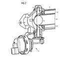
- the Gezzauseflansaku is shown in perspective view with a connected gas cooler 9.
- the gas cooler 9 has an inner channel 8 and outer channels 12.
- the Gezzauseflanheitheit serves as a closure unit for the gas cooler with respect to the inner channel 8.
- the inner dimensions of the inner channel 8 are consistent with the outer dimensions of the flap 3 in compliance with tolerances, so that the inner channel 8 of the gas cooler 9 can be completely closed by the flap 3 , In this case (not shown), the flowing in the direction of arrow in the Gescouseflanheitheit flowing media are directed into the outer channels 12, which are usually washed with cooling water and the flowing media thus cool.
- the Gezzauseflanheitheit is particularly suitable as a closure unit for a gas cooler 9 for exhaust gases of a motor vehicle.
Landscapes
- Engineering & Computer Science (AREA)
- General Engineering & Computer Science (AREA)
- Mechanical Engineering (AREA)
- Chemical & Material Sciences (AREA)
- Combustion & Propulsion (AREA)
- Lift Valve (AREA)
- Control Of Throttle Valves Provided In The Intake System Or In The Exhaust System (AREA)
- Valve Housings (AREA)
Claims (4)
- Ensemble bride de carter, qui se compose d'une bride de carter (1), dans laquelle, perpendiculairement à l'axe longitudinal de la bride de carter (1), un arbre de clapet (2), portant un clapet (3) placé en son centre, est suspendu en rotation sur un premier palier (4) et un deuxième palier (5), ledit arbre de clapet comportant, sur le côté extérieur du premier palier (4), un disque circulaire (6) qui s'insère dans un siège (10) en forme de gobelet de la bride de carter (1), caractérisé par le fait que, pour l'étanchéification de l'arbre (2) du clapet dans la bride de carter (1), le disque circulaire (6) est fixé par soudure à l'arbre du clapet (2) ou est exécuté comme épaulement de l'arbre du clapet et que, dans la bride de carter (1), est fixé un pot (7) comportant un évidement circulaire dans lequel s'insère le disque circulaire (6).
- Ensemble bride de carter selon la revendication 1, dans lequel l'extrémité de l'arbre du clapet (2) positionnée près du premier palier (4) est liée à un mécanisme de commande (11).
- Utilisation de l'ensemble bride de carter selon la revendication 1 ou la revendication 2, en tant qu'ensemble d'obturation pour un radiateur de gaz (9) comportant un canal intérieur (8), dont les dimensions intérieures concordent avec les dimensions extérieures du clapet (3), tout en respectant des tolérances.
- Utilisation selon la revendication 3 en tant qu'ensemble d'obturation pour un radiateur (9) de gaz d'échappement d'un véhicule automobile.
Applications Claiming Priority (3)
| Application Number | Priority Date | Filing Date | Title |
|---|---|---|---|
| DE10251179 | 2002-10-31 | ||
| DE10251179A DE10251179A1 (de) | 2002-10-31 | 2002-10-31 | Gehäuseflanscheinheit |
| PCT/DE2003/003183 WO2004040109A1 (fr) | 2002-10-31 | 2003-09-24 | Ensemble bride de carter |
Publications (2)
| Publication Number | Publication Date |
|---|---|
| EP1556599A1 EP1556599A1 (fr) | 2005-07-27 |
| EP1556599B1 true EP1556599B1 (fr) | 2007-03-21 |
Family
ID=32103289
Family Applications (1)
| Application Number | Title | Priority Date | Filing Date |
|---|---|---|---|
| EP03773455A Expired - Lifetime EP1556599B1 (fr) | 2002-10-31 | 2003-09-24 | Ensemble bride de carter |
Country Status (5)
| Country | Link |
|---|---|
| US (1) | US7198252B2 (fr) |
| EP (1) | EP1556599B1 (fr) |
| JP (1) | JP2006504042A (fr) |
| DE (2) | DE10251179A1 (fr) |
| WO (1) | WO2004040109A1 (fr) |
Families Citing this family (2)
| Publication number | Priority date | Publication date | Assignee | Title |
|---|---|---|---|---|
| EP1685322A1 (fr) * | 2003-10-17 | 2006-08-02 | Honeywell International, Inc. | Refroidisseur de gaz d'echappement a conduite de derivation interne |
| DE102016122045B4 (de) * | 2015-11-30 | 2022-09-29 | Cummins Inc. | WASTEGATE- und MOTOR-ANORDNUNG sowie Verfahren zum Betreiben eines Motors |
Family Cites Families (21)
| Publication number | Priority date | Publication date | Assignee | Title |
|---|---|---|---|---|
| AT142057B (de) * | 1933-06-14 | 1935-06-11 | Befa Beteiligungs & Finanzieru | Einrichtung zur Anpassung von Absperrklappen an verschiedene Durchströmquerschnitte. |
| DE922800C (de) * | 1952-12-23 | 1955-01-24 | Kloeckner Humboldt Deutz Ag | Drosselklappe in einem kugelartigen Gehaeuse der Auspuffleitung zur Verstaerkung derBremswirkung |
| FR2255522B1 (fr) * | 1973-12-19 | 1982-11-12 | Amri | |
| US4022424A (en) * | 1975-09-29 | 1977-05-10 | General Electric Company | Shaft bearing and seals for butterfly valves |
| DE3707904A1 (de) * | 1987-03-12 | 1988-09-22 | Sueddeutsche Kuehler Behr | Klappenventil fuer eine abgasleitung eines kraftfahrzeuges |
| JPH02149733A (ja) * | 1988-11-30 | 1990-06-08 | Hitachi Ltd | 電動絞弁制御装置 |
| US4938452A (en) * | 1988-12-10 | 1990-07-03 | Aisan Kogyo Kabushiki Kaisha | Air control device for internal combustion engine |
| DE4019264A1 (de) * | 1990-06-16 | 1991-12-19 | Vdo Schindling | Arretierungsvorrichtung |
| DE4205496C1 (fr) | 1992-02-22 | 1993-01-28 | Mercedes-Benz Aktiengesellschaft, 7000 Stuttgart, De | |
| DE4413145C2 (de) * | 1994-04-15 | 1999-11-04 | Daimler Chrysler Ag | Drosselklappenanordnung, insbesondere für eine Kraftfahrzeug-Abgasanlage |
| FR2731766B1 (fr) * | 1995-03-14 | 1997-05-23 | Ksb Ag | Dispositif de robinetteries |
| DE19510622A1 (de) * | 1995-03-23 | 1996-09-26 | Bosch Gmbh Robert | Drosselvorrichtung und Verfahren zur Herstellung einer Drosselvorrichtung |
| US5630571A (en) * | 1995-10-16 | 1997-05-20 | General Motors Corporation | Exhaust flow control valve |
| JPH1019140A (ja) * | 1996-07-05 | 1998-01-23 | Kubota Corp | 二重構造管路用弁装置 |
| FR2754583B1 (fr) * | 1996-10-11 | 1998-12-31 | Ecia Equip Composants Ind Auto | Vanne, notamment pour tubulure d'une ligne d'echappement |
| US5953898A (en) | 1997-02-26 | 1999-09-21 | Foster Wheeler Energia Oy | Power generation method including control of temperature of flue gases entering a high temperature ceramic filter |
| US5839717A (en) * | 1997-03-25 | 1998-11-24 | Feigel; Kurt R. | Valve with improved shaft retainer |
| DE10045109A1 (de) * | 2000-09-12 | 2002-03-21 | Horst Schuth | Schaltwellenabdichtung |
| US6595488B2 (en) * | 2001-01-19 | 2003-07-22 | Zwick Gmbh | Butterfly valve |
| DE10142411A1 (de) * | 2001-08-31 | 2003-04-03 | Siemens Ag | Einstückige Ventilklappe und Rotationsventil |
| JP4446635B2 (ja) * | 2001-09-03 | 2010-04-07 | 本田技研工業株式会社 | 内燃機関の排ガス弁装置 |
-
2002
- 2002-10-31 DE DE10251179A patent/DE10251179A1/de not_active Withdrawn
-
2003
- 2003-09-24 WO PCT/DE2003/003183 patent/WO2004040109A1/fr not_active Ceased
- 2003-09-24 JP JP2004547388A patent/JP2006504042A/ja active Pending
- 2003-09-24 EP EP03773455A patent/EP1556599B1/fr not_active Expired - Lifetime
- 2003-09-24 DE DE50306868T patent/DE50306868D1/de not_active Expired - Lifetime
-
2005
- 2005-04-25 US US11/113,008 patent/US7198252B2/en not_active Expired - Fee Related
Also Published As
| Publication number | Publication date |
|---|---|
| DE50306868D1 (de) | 2007-05-03 |
| JP2006504042A (ja) | 2006-02-02 |
| US20050236598A1 (en) | 2005-10-27 |
| EP1556599A1 (fr) | 2005-07-27 |
| US7198252B2 (en) | 2007-04-03 |
| WO2004040109A1 (fr) | 2004-05-13 |
| DE10251179A1 (de) | 2004-05-13 |
Similar Documents
| Publication | Publication Date | Title |
|---|---|---|
| DE60302743T2 (de) | Ventil mit selbstreiningender Drosselvorrichtung | |
| DE60009590T2 (de) | Abgasrückführungssystem und Betätigungsvorrichtung dafür | |
| EP1509692B1 (fr) | Echangeur de chaleur des gaz d'echappement a commutation | |
| DE102009035349B4 (de) | Steuervorrichtung für den Kühlmittelfluss im Kühlkreislauf einer Brennkraftmaschine | |
| EP2025911B1 (fr) | Dispositif de refroidissement de gaz d'échappement pour un moteur à combustion interne | |
| DE102012101322A1 (de) | Turbolader | |
| DE102020100252A1 (de) | Steuerventil | |
| DE10329336A1 (de) | Klappenventil | |
| DE102018111139A1 (de) | Ventileinrichtung | |
| DE10392436T5 (de) | Elektrisch gesteuertes Ventil für eine Fluidzirkulationsschaltung | |
| EP1510739A1 (fr) | Soupape d'échappement | |
| DE102016107933B4 (de) | Ventil für einen Abgasstrang einer Brennkraftmaschine und Verfahren zum Steuern von zwei Abgasströmen | |
| EP1556599B1 (fr) | Ensemble bride de carter | |
| EP1431527A1 (fr) | Dispositif de refroidissement de gaz | |
| DE102007007111A1 (de) | Klappenventil | |
| EP1556638A1 (fr) | Soupape | |
| EP1573240B1 (fr) | Soupape | |
| DE102004049292A1 (de) | Zylinderkopfdichtung | |
| WO2006024495A1 (fr) | Soupape en particulier soupape de piston rotatif, et systeme de retour des gaz d'echappement comprenant une soupape de ce type | |
| DE10101412A1 (de) | Abgasrückführeinrichtung für eine Brennkraftmaschine | |
| DE102005041146A1 (de) | Ventil, insbesondere Drehkolbenventil, und Abgasrückführsystem mit einem solchen Ventil | |
| DE102015111252B4 (de) | Ventil für einen Abgasstrang einer Brennkraftmaschine | |
| WO2007022807A1 (fr) | Echangeur de chaleur, notamment refroidisseur d'huile pour un moteur a combustion interne | |
| DE102019219399B4 (de) | Ventilklappe zur Steuerung eines Fluiddurchflusses durch einen Strömungskanal und Ventil | |
| DE3507654C2 (de) | Sammler für einen Wärmetauscher einer Heizungs- und Klimaanlge eines Kraftfahrzeuges |
Legal Events
| Date | Code | Title | Description |
|---|---|---|---|
| PUAI | Public reference made under article 153(3) epc to a published international application that has entered the european phase |
Free format text: ORIGINAL CODE: 0009012 |
|
| 17P | Request for examination filed |
Effective date: 20050401 |
|
| AK | Designated contracting states |
Kind code of ref document: A1 Designated state(s): AT BE BG CH CY CZ DE DK EE ES FI FR GB GR HU IE IT LI LU MC NL PT RO SE SI SK TR |
|
| AX | Request for extension of the european patent |
Extension state: AL LT LV MK |
|
| DAX | Request for extension of the european patent (deleted) | ||
| RBV | Designated contracting states (corrected) |
Designated state(s): DE FR |
|
| GRAP | Despatch of communication of intention to grant a patent |
Free format text: ORIGINAL CODE: EPIDOSNIGR1 |
|
| GRAS | Grant fee paid |
Free format text: ORIGINAL CODE: EPIDOSNIGR3 |
|
| GRAA | (expected) grant |
Free format text: ORIGINAL CODE: 0009210 |
|
| AK | Designated contracting states |
Kind code of ref document: B1 Designated state(s): DE FR |
|
| REF | Corresponds to: |
Ref document number: 50306868 Country of ref document: DE Date of ref document: 20070503 Kind code of ref document: P |
|
| ET | Fr: translation filed | ||
| PLBE | No opposition filed within time limit |
Free format text: ORIGINAL CODE: 0009261 |
|
| STAA | Information on the status of an ep patent application or granted ep patent |
Free format text: STATUS: NO OPPOSITION FILED WITHIN TIME LIMIT |
|
| 26N | No opposition filed |
Effective date: 20071227 |
|
| REG | Reference to a national code |
Ref country code: FR Ref legal event code: TP |
|
| PGFP | Annual fee paid to national office [announced via postgrant information from national office to epo] |
Ref country code: FR Payment date: 20121010 Year of fee payment: 10 |
|
| REG | Reference to a national code |
Ref country code: FR Ref legal event code: ST Effective date: 20140530 |
|
| PG25 | Lapsed in a contracting state [announced via postgrant information from national office to epo] |
Ref country code: FR Free format text: LAPSE BECAUSE OF NON-PAYMENT OF DUE FEES Effective date: 20130930 |
|
| PGFP | Annual fee paid to national office [announced via postgrant information from national office to epo] |
Ref country code: DE Payment date: 20160930 Year of fee payment: 14 |
|
| REG | Reference to a national code |
Ref country code: DE Ref legal event code: R119 Ref document number: 50306868 Country of ref document: DE |
|
| PG25 | Lapsed in a contracting state [announced via postgrant information from national office to epo] |
Ref country code: DE Free format text: LAPSE BECAUSE OF NON-PAYMENT OF DUE FEES Effective date: 20180404 |