EP1556600B1 - Soupape - Google Patents
Soupape Download PDFInfo
- Publication number
- EP1556600B1 EP1556600B1 EP03773468A EP03773468A EP1556600B1 EP 1556600 B1 EP1556600 B1 EP 1556600B1 EP 03773468 A EP03773468 A EP 03773468A EP 03773468 A EP03773468 A EP 03773468A EP 1556600 B1 EP1556600 B1 EP 1556600B1
- Authority
- EP
- European Patent Office
- Prior art keywords
- sealing ring
- gap
- piston sealing
- flap
- ring
- Prior art date
- Legal status (The legal status is an assumption and is not a legal conclusion. Google has not performed a legal analysis and makes no representation as to the accuracy of the status listed.)
- Expired - Lifetime
Links
- 238000007789 sealing Methods 0.000 claims abstract description 36
- 229910052751 metal Inorganic materials 0.000 claims abstract description 7
- 239000002184 metal Substances 0.000 claims abstract description 7
- 229910000831 Steel Inorganic materials 0.000 claims description 4
- 239000011324 bead Substances 0.000 claims description 4
- 239000010959 steel Substances 0.000 claims description 4
- 229910052782 aluminium Inorganic materials 0.000 claims description 3
- XAGFODPZIPBFFR-UHFFFAOYSA-N aluminium Chemical compound [Al] XAGFODPZIPBFFR-UHFFFAOYSA-N 0.000 claims description 3
- 238000003466 welding Methods 0.000 claims description 2
- 239000004411 aluminium Substances 0.000 claims 1
- 239000007789 gas Substances 0.000 description 11
- 230000015572 biosynthetic process Effects 0.000 description 3
- 230000035939 shock Effects 0.000 description 1
Images
Classifications
-
- F—MECHANICAL ENGINEERING; LIGHTING; HEATING; WEAPONS; BLASTING
- F16—ENGINEERING ELEMENTS AND UNITS; GENERAL MEASURES FOR PRODUCING AND MAINTAINING EFFECTIVE FUNCTIONING OF MACHINES OR INSTALLATIONS; THERMAL INSULATION IN GENERAL
- F16K—VALVES; TAPS; COCKS; ACTUATING-FLOATS; DEVICES FOR VENTING OR AERATING
- F16K1/00—Lift valves or globe valves, i.e. cut-off apparatus with closure members having at least a component of their opening and closing motion perpendicular to the closing faces
- F16K1/16—Lift valves or globe valves, i.e. cut-off apparatus with closure members having at least a component of their opening and closing motion perpendicular to the closing faces with pivoted closure-members
- F16K1/18—Lift valves or globe valves, i.e. cut-off apparatus with closure members having at least a component of their opening and closing motion perpendicular to the closing faces with pivoted closure-members with pivoted discs or flaps
- F16K1/22—Lift valves or globe valves, i.e. cut-off apparatus with closure members having at least a component of their opening and closing motion perpendicular to the closing faces with pivoted closure-members with pivoted discs or flaps with axis of rotation crossing the valve member, e.g. butterfly valves
- F16K1/226—Shaping or arrangements of the sealing
- F16K1/2261—Shaping or arrangements of the sealing the sealing being arranged on the valve member
-
- F—MECHANICAL ENGINEERING; LIGHTING; HEATING; WEAPONS; BLASTING
- F02—COMBUSTION ENGINES; HOT-GAS OR COMBUSTION-PRODUCT ENGINE PLANTS
- F02D—CONTROLLING COMBUSTION ENGINES
- F02D9/00—Controlling engines by throttling air or fuel-and-air induction conduits or exhaust conduits
- F02D9/08—Throttle valves specially adapted therefor; Arrangements of such valves in conduits
- F02D9/10—Throttle valves specially adapted therefor; Arrangements of such valves in conduits having pivotally-mounted flaps
- F02D9/1005—Details of the flap
- F02D9/101—Special flap shapes, ribs, bores or the like
- F02D9/1015—Details of the edge of the flap, e.g. for lowering flow noise or improving flow sealing in closed flap position
-
- F—MECHANICAL ENGINEERING; LIGHTING; HEATING; WEAPONS; BLASTING
- F02—COMBUSTION ENGINES; HOT-GAS OR COMBUSTION-PRODUCT ENGINE PLANTS
- F02M—SUPPLYING COMBUSTION ENGINES IN GENERAL WITH COMBUSTIBLE MIXTURES OR CONSTITUENTS THEREOF
- F02M26/00—Engine-pertinent apparatus for adding exhaust gases to combustion-air, main fuel or fuel-air mixture, e.g. by exhaust gas recirculation [EGR] systems
- F02M26/65—Constructional details of EGR valves
- F02M26/70—Flap valves; Rotary valves; Sliding valves; Resilient valves
Definitions
- the invention relates to a valve as a gas recirculation valve of a motor vehicle.
- Valves for example for gas channels are known. They often consist of a housing with a valve seat, in which a rotatably arranged flap for closing the gas channel is arranged. To avoid leakage air, the flap is provided with an outer circumferential piston seal. This usually consists of a metal ring, which has a gap for reasons of compliance. In operation, this causes the disadvantage that this gap often can not be completely closed, so that leakage air is guided through this gap, which is not desirable.
- a valve which consists of a housing with a valve seat for a flap, which is rotatably mounted on a drive shaft, in which outside of the flap a first piston sealing ring and a second piston sealing ring in one circumferential groove of the flap are arranged, which are each designed as a metal ring with a first gap or a second gap, which are not aligned.
- This valve is used as a pipe seal.
- the invention is therefore based on the object to provide a simple valve for a gas passage in a motor vehicle, in which the formation of leakage air can be largely avoided.
- a secure closing of the gas channel should therefore be largely ensured even at higher and fluctuating temperatures of the gas.
- the object underlying the invention is achieved by a gas recirculation valve with the features of claim 1.
- the use of the valve according to the invention is to be regarded as particularly advantageous because the gases conducted through a gas recirculation valve of a motor vehicle generally have high temperatures and high temperature fluctuations and yet the formation of leakage air is avoided.
- the valve seat can for example be itself a part of the housing.
- the flap is usually circular and made of steel, for example.
- the first piston sealing ring and the second piston sealing ring are each formed as a flat metal ring.
- the first piston sealing ring has a first gap.
- the second piston sealing ring has the second gap. In the first gap and at the second gap one speaks each of a shock game.
- a first variant of the invention consists in that in each case a weld point is arranged in the groove of the flap at the location of the first gap and at the location of the second gap. It is advantageous that both the first piston sealing ring and the second piston sealing ring, for example, do not have to be connected at one point with the flap.
- the welds in the groove of the flap prevent in a relatively simple manner an alignment of the first gap with the second gap.
- the first piston sealing ring or the second piston sealing ring has corrugations on its respective flat side facing the adjacent piston sealing ring.
- the beads are punctiform projections, which are located directly on the respective flat side.
- the beads press each other on or in the flat side of the adjacent piston sealing ring, which leads in an advantageous manner to that an alignment of the first gap with the second gap is also avoided.
- this measure may even be sufficient alone to prevent alignment of the first gap with the second gap, so that further precautions to avoid such alignment are not required.
- valve seat is designed as a steel ring which is pressed in the housing. In this way, the wear resistance of the valve seat is advantageously increased.
- a further embodiment of the invention is that a housing made of aluminum is arranged. As a result, the weight of the valve can be reduced, while the wear resistance is given in the valve seat.
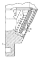
- Fig. Shows the valve in cross section.
- the valve is shown in cross section.
- the valve consists of a housing 5 with a valve seat 4 for a flap 2, which is rotatably mounted on a drive shaft 1.
- a first piston sealing ring 3a and a second piston sealing ring 3b are arranged in a circumferential groove of the flap 2.
- the first piston sealing ring 3a is designed as a flat metal ring with a first gap 3 '.
- the second piston sealing ring 3b is designed as a flat metal ring with a second gap 3 "The first gap 3 'and the second gap 3" do not align with one another.
- the valve seat 4 is designed as a steel ring, which is in the housing 5, which is made of aluminum in an advantageous manner, is pressed.
- the valve is particularly suitable as a gas recirculation valve of a motor vehicle.
Landscapes
- Engineering & Computer Science (AREA)
- General Engineering & Computer Science (AREA)
- Mechanical Engineering (AREA)
- Chemical & Material Sciences (AREA)
- Combustion & Propulsion (AREA)
- Lift Valve (AREA)
- Sliding Valves (AREA)
- Sealing Devices (AREA)
Abstract
Claims (3)
- Soupape de réinjection des gaz dans un véhicule automobile, avec un corps de soupape (5) qui comporte un siège de soupape (4) pour un clapet (2), lequel est monté en rotation sur un arbre d'entraînement (1), où sont disposés extérieurement autour du clapet (2), dans une rainure périphérique du clapet (2), un premier segment d'étanchéité (3a) et un deuxième segment d'étanchéité (3b), qui sont chacun exécutés en tant que bague en métal avec une première fente (3') et, respectivement, une deuxième fente (3") qui ne sont pas en alignement l'une sur l'autre,
caractérisée par le fait que le premier segment d'étanchéité (3a) et le deuxième segment d'étanchéité (3b) sont maintenus dans leur position relative radiale par le fait que, dans la rainure périphérique du clapet (2), est disposé un point de soudure à l'endroit de la première fente (3') et à l'endroit de la deuxième fente (3") et/ou que le premier segment d'étanchéité (3a) et le deuxième segment d'étanchéité (3b) comportent des collets sur la face plate qui est tournée vers le segment d'étanchéité (3a, 3b) voisin. - Soupape de réinjection des gaz selon la revendication 1,
caractérisée par le fait que le siège de soupape (4) est conçu comme bague en acier qui est engagée par pression dans le corps de soupape (5). - Soupape de réinjection des gaz selon la revendication 2,
caractérisée par le fait que le corps de soupape (5) est en aluminium.
Applications Claiming Priority (3)
| Application Number | Priority Date | Filing Date | Title |
|---|---|---|---|
| DE10251384 | 2002-11-01 | ||
| DE10251384A DE10251384A1 (de) | 2002-11-01 | 2002-11-01 | Ventil |
| PCT/DE2003/003262 WO2004040110A1 (fr) | 2002-11-01 | 2003-09-30 | Soupape |
Publications (2)
| Publication Number | Publication Date |
|---|---|
| EP1556600A1 EP1556600A1 (fr) | 2005-07-27 |
| EP1556600B1 true EP1556600B1 (fr) | 2006-11-22 |
Family
ID=32103331
Family Applications (1)
| Application Number | Title | Priority Date | Filing Date |
|---|---|---|---|
| EP03773468A Expired - Lifetime EP1556600B1 (fr) | 2002-11-01 | 2003-09-30 | Soupape |
Country Status (4)
| Country | Link |
|---|---|
| US (1) | US7007926B2 (fr) |
| EP (1) | EP1556600B1 (fr) |
| DE (2) | DE10251384A1 (fr) |
| WO (1) | WO2004040110A1 (fr) |
Families Citing this family (9)
| Publication number | Priority date | Publication date | Assignee | Title |
|---|---|---|---|---|
| DE10260252A1 (de) * | 2002-12-20 | 2004-07-22 | Siemens Ag | Ventil |
| DE102005048417A1 (de) * | 2005-10-10 | 2007-04-12 | Siemens Ag | Toleranzring für eine Drosselklappe |
| DE102007010536A1 (de) * | 2007-03-05 | 2008-09-11 | Continental Automotive Gmbh | Ventil |
| DE102007014373A1 (de) * | 2007-03-26 | 2008-10-30 | Continental Automotive Gmbh | Ventil |
| DE102007027234A1 (de) | 2007-06-13 | 2008-12-18 | Continental Automotive Gmbh | Ventil |
| EP2339243A1 (fr) * | 2009-12-22 | 2011-06-29 | Convotherm Elektrogeräte GmbH | Appareil de cuisson industriel, en particulier four de cuisson à la vapeur |
| CN102390023A (zh) * | 2010-12-11 | 2012-03-28 | 西安合升动力科技有限公司 | 防尘密封型交流永磁同步电主轴 |
| DE102010054864A1 (de) * | 2010-12-17 | 2012-06-21 | Continental Automotive Gmbh | Ventil und Verwendung des Ventils |
| CN104674775B (zh) * | 2015-03-05 | 2017-08-25 | 黄河养护集团有限公司 | 排灌水泵自动拍门及其制造和施工方法 |
Family Cites Families (27)
| Publication number | Priority date | Publication date | Assignee | Title |
|---|---|---|---|---|
| US1419781A (en) * | 1921-03-05 | 1922-06-13 | Christ W Trippensee | Piston ring |
| US1860619A (en) * | 1930-07-12 | 1932-05-31 | Allis Chalmers Mfg Co | Valve |
| US1956513A (en) * | 1933-08-04 | 1934-04-24 | Grover C Neault | Piston ring |
| US2059656A (en) * | 1935-12-21 | 1936-11-03 | Allis Chalmers Mfg Co | Butterfly valve |
| US2380821A (en) * | 1941-01-21 | 1945-07-31 | Allegheny Ludlum Steel | Poppet valve and valve seat for internal-combustion engines |
| US2840338A (en) * | 1953-04-10 | 1958-06-24 | Standard Thomson Corp | Butterfly valve |
| GB732184A (en) * | 1953-05-20 | 1955-06-22 | Teddington Aircraft Controls L | Improvements in or relating to butterfly valves |
| US3991455A (en) * | 1972-04-10 | 1976-11-16 | Alfred Bergeron | Coupled piston ring method of manufacture |
| US3905577A (en) * | 1973-03-08 | 1975-09-16 | Anchor Darling Valve Co | Valve |
| US3902697A (en) * | 1973-09-27 | 1975-09-02 | Milwaukee Valve | Butterfly valve |
| NL7402578A (nl) * | 1974-02-26 | 1975-08-28 | Philips Nv | Kathodestraalbuis voor het weergeven van ge- kleurde beelden. |
| DE2443723B2 (de) * | 1974-09-12 | 1976-07-29 | Gebr. Adams, 4630 Bochum | Klappenventil |
| US4240644A (en) * | 1977-04-27 | 1980-12-23 | Gemini Seals, Inc. | Piston seal |
| US4290615A (en) * | 1979-12-14 | 1981-09-22 | International Telephone And Telegraph Corporation | Butterfly valve |
| US4384729A (en) * | 1981-05-20 | 1983-05-24 | Benjamin Birenbaum | Interlocking dual plane gapped compression rings |
| US4632360A (en) * | 1981-08-14 | 1986-12-30 | United Aircraft Products, Inc. | Butterfly type valve seal |
| JPH01188772A (ja) * | 1988-01-21 | 1989-07-28 | Akira Oshima | バタフライ弁の正逆両圧シール装置 |
| DE3839968A1 (de) * | 1988-11-26 | 1990-05-31 | Audi Ag | Turbinengehaeuse eines abgasturboladers |
| JPH0296402U (fr) * | 1989-01-19 | 1990-08-01 | ||
| FR2683289B1 (fr) * | 1991-11-04 | 1995-02-17 | Alain Verdelet | Joint pour vanne a papillon et vanne a papillon pourvue d'un tel joint. |
| US5326077A (en) * | 1993-10-04 | 1994-07-05 | General Electric Company | Butterfly valve seal retainer |
| US5531205A (en) * | 1995-03-31 | 1996-07-02 | Siemens Electric Limited | Rotary diesel electric EGR valve |
| US6135415A (en) * | 1998-07-30 | 2000-10-24 | Siemens Canada Limited | Exhaust gas recirculation assembly |
| DE19934113A1 (de) * | 1999-07-21 | 2001-01-25 | Bosch Gmbh Robert | Klappenventil |
| EP1242760A4 (fr) * | 1999-12-29 | 2005-03-23 | Visteon Global Tech Inc | Soupape d'echappement pour moteurs a combustion |
| US6739579B1 (en) * | 1999-12-29 | 2004-05-25 | Visteon Global Technologies, Inc. | Exhaust valve for combustion engines |
| US6439255B1 (en) * | 2000-11-17 | 2002-08-27 | Mks Instruments, Inc. | Valve flapper with dynamic circumference seal |
-
2002
- 2002-11-01 DE DE10251384A patent/DE10251384A1/de not_active Withdrawn
-
2003
- 2003-09-30 EP EP03773468A patent/EP1556600B1/fr not_active Expired - Lifetime
- 2003-09-30 WO PCT/DE2003/003262 patent/WO2004040110A1/fr not_active Ceased
- 2003-09-30 DE DE50305790T patent/DE50305790D1/de not_active Expired - Lifetime
-
2004
- 2004-12-20 US US11/014,994 patent/US7007926B2/en not_active Expired - Fee Related
Also Published As
| Publication number | Publication date |
|---|---|
| DE50305790D1 (de) | 2007-01-04 |
| US20050129550A1 (en) | 2005-06-16 |
| US7007926B2 (en) | 2006-03-07 |
| WO2004040110A1 (fr) | 2004-05-13 |
| DE10251384A1 (de) | 2004-05-13 |
| EP1556600A1 (fr) | 2005-07-27 |
Similar Documents
| Publication | Publication Date | Title |
|---|---|---|
| DE102012101322B4 (de) | Turbolader | |
| EP0877183B1 (fr) | Joint de culasse métallique | |
| DE102011077766A1 (de) | Betätigungseinrichtung für ein Abgasstrom-Steuerelement eines Abgasturboladers | |
| EP1556600B1 (fr) | Soupape | |
| EP3430250B1 (fr) | Dispositif de ressort pour un volet wastegate et dispositif de soupape pour un turbochargeur | |
| DE60206333T2 (de) | Kopfdichtung | |
| DE102009027758A1 (de) | Motorzylinderkopfdichtungsanordnung | |
| EP2020544B1 (fr) | Soupape, en particulier soupape de recyclage de gaz d'échappement | |
| DE4426471A1 (de) | Drehabsperrorgan | |
| EP1573240B1 (fr) | Soupape | |
| DE102008057207A1 (de) | Welleneinrichtung mit einer Dichtungsvorrichtung | |
| EP1556638A1 (fr) | Soupape | |
| WO2023169669A1 (fr) | Soupape à tiroir rotatif pour circuit de refroidissement de véhicule automobile | |
| DE2450914C2 (de) | Dichtung, insbesondere Flachdichtung | |
| EP1561057B1 (fr) | Soupape | |
| DE2753264C2 (de) | Steuerscheibenventil, insbesondere Sanitärventil | |
| DE4411050A1 (de) | Kugelhahn | |
| DE19629203B4 (de) | Hydraulische Spielausgleichsvorrichtung | |
| DE4417669A1 (de) | Absperrarmatur zum Absperren einer Strömung | |
| DE102004024056A1 (de) | Ventil für eine Abgasleitung | |
| WO2007022807A1 (fr) | Echangeur de chaleur, notamment refroidisseur d'huile pour un moteur a combustion interne | |
| DE102014207671B4 (de) | Abgasturbolader mit einem Wastegate-Ventil | |
| EP1556599B1 (fr) | Ensemble bride de carter | |
| EP1182386A2 (fr) | Dispositif d'arrêt avec joint d'étanchéité | |
| WO2025056745A1 (fr) | Soupape, système modulaire, siège de soupape, tige de soupape et procédé de production |
Legal Events
| Date | Code | Title | Description |
|---|---|---|---|
| PUAI | Public reference made under article 153(3) epc to a published international application that has entered the european phase |
Free format text: ORIGINAL CODE: 0009012 |
|
| AK | Designated contracting states |
Kind code of ref document: A1 Designated state(s): AT BE BG CH CY CZ DE DK EE ES FI FR GB GR HU IE IT LI LU MC NL PT RO SE SI SK TR |
|
| AX | Request for extension of the european patent |
Extension state: AL LT LV MK |
|
| 17P | Request for examination filed |
Effective date: 20041119 |
|
| DAX | Request for extension of the european patent (deleted) | ||
| RBV | Designated contracting states (corrected) |
Designated state(s): DE FR |
|
| GRAP | Despatch of communication of intention to grant a patent |
Free format text: ORIGINAL CODE: EPIDOSNIGR1 |
|
| GRAS | Grant fee paid |
Free format text: ORIGINAL CODE: EPIDOSNIGR3 |
|
| GRAA | (expected) grant |
Free format text: ORIGINAL CODE: 0009210 |
|
| AK | Designated contracting states |
Kind code of ref document: B1 Designated state(s): DE FR |
|
| REF | Corresponds to: |
Ref document number: 50305790 Country of ref document: DE Date of ref document: 20070104 Kind code of ref document: P |
|
| ET | Fr: translation filed | ||
| PLBE | No opposition filed within time limit |
Free format text: ORIGINAL CODE: 0009261 |
|
| STAA | Information on the status of an ep patent application or granted ep patent |
Free format text: STATUS: NO OPPOSITION FILED WITHIN TIME LIMIT |
|
| 26N | No opposition filed |
Effective date: 20070823 |
|
| REG | Reference to a national code |
Ref country code: FR Ref legal event code: TP |
|
| REG | Reference to a national code |
Ref country code: FR Ref legal event code: PLFP Year of fee payment: 14 |
|
| PGFP | Annual fee paid to national office [announced via postgrant information from national office to epo] |
Ref country code: DE Payment date: 20160930 Year of fee payment: 14 |
|
| REG | Reference to a national code |
Ref country code: FR Ref legal event code: PLFP Year of fee payment: 15 |
|
| PGFP | Annual fee paid to national office [announced via postgrant information from national office to epo] |
Ref country code: FR Payment date: 20170928 Year of fee payment: 15 |
|
| REG | Reference to a national code |
Ref country code: DE Ref legal event code: R119 Ref document number: 50305790 Country of ref document: DE |
|
| PG25 | Lapsed in a contracting state [announced via postgrant information from national office to epo] |
Ref country code: DE Free format text: LAPSE BECAUSE OF NON-PAYMENT OF DUE FEES Effective date: 20180404 |
|
| PG25 | Lapsed in a contracting state [announced via postgrant information from national office to epo] |
Ref country code: FR Free format text: LAPSE BECAUSE OF NON-PAYMENT OF DUE FEES Effective date: 20180930 |