EP1556624B1 - Vorrichtung zum zumindest durchleiten und/oder übertragen von drehmoment - Google Patents
Vorrichtung zum zumindest durchleiten und/oder übertragen von drehmoment Download PDFInfo
- Publication number
- EP1556624B1 EP1556624B1 EP03809262A EP03809262A EP1556624B1 EP 1556624 B1 EP1556624 B1 EP 1556624B1 EP 03809262 A EP03809262 A EP 03809262A EP 03809262 A EP03809262 A EP 03809262A EP 1556624 B1 EP1556624 B1 EP 1556624B1
- Authority
- EP
- European Patent Office
- Prior art keywords
- shaft
- housing
- component
- protective cap
- discharge ring
- Prior art date
- Legal status (The legal status is an assumption and is not a legal conclusion. Google has not performed a legal analysis and makes no representation as to the accuracy of the status listed.)
- Expired - Lifetime
Links
- 230000002463 transducing effect Effects 0.000 title abstract 2
- 230000001681 protective effect Effects 0.000 claims description 14
- 230000005540 biological transmission Effects 0.000 claims description 10
- 239000000463 material Substances 0.000 claims description 7
- 230000006378 damage Effects 0.000 claims description 5
- 239000000314 lubricant Substances 0.000 description 5
- 239000002184 metal Substances 0.000 description 4
- 230000001050 lubricating effect Effects 0.000 description 3
- 239000004033 plastic Substances 0.000 description 3
- 229920003023 plastic Polymers 0.000 description 3
- 239000004020 conductor Substances 0.000 description 2
- 230000005611 electricity Effects 0.000 description 2
- 239000007787 solid Substances 0.000 description 2
- OKTJSMMVPCPJKN-UHFFFAOYSA-N Carbon Chemical compound [C] OKTJSMMVPCPJKN-UHFFFAOYSA-N 0.000 description 1
- 230000032683 aging Effects 0.000 description 1
- 238000001311 chemical methods and process Methods 0.000 description 1
- 238000010276 construction Methods 0.000 description 1
- 230000007797 corrosion Effects 0.000 description 1
- 238000005260 corrosion Methods 0.000 description 1
- 230000001419 dependent effect Effects 0.000 description 1
- 238000009795 derivation Methods 0.000 description 1
- 238000007599 discharging Methods 0.000 description 1
- 229910002804 graphite Inorganic materials 0.000 description 1
- 239000010439 graphite Substances 0.000 description 1
- 239000012212 insulator Substances 0.000 description 1
- 239000010687 lubricating oil Substances 0.000 description 1
- 238000000034 method Methods 0.000 description 1
- 230000003647 oxidation Effects 0.000 description 1
- 238000007254 oxidation reaction Methods 0.000 description 1
- 238000005096 rolling process Methods 0.000 description 1
- 230000003068 static effect Effects 0.000 description 1
- 230000035882 stress Effects 0.000 description 1
Images

Classifications
-
- F—MECHANICAL ENGINEERING; LIGHTING; HEATING; WEAPONS; BLASTING
- F16—ENGINEERING ELEMENTS AND UNITS; GENERAL MEASURES FOR PRODUCING AND MAINTAINING EFFECTIVE FUNCTIONING OF MACHINES OR INSTALLATIONS; THERMAL INSULATION IN GENERAL
- F16C—SHAFTS; FLEXIBLE SHAFTS; ELEMENTS OR CRANKSHAFT MECHANISMS; ROTARY BODIES OTHER THAN GEARING ELEMENTS; BEARINGS
- F16C19/00—Bearings with rolling contact, for exclusively rotary movement
- F16C19/52—Bearings with rolling contact, for exclusively rotary movement with devices affected by abnormal or undesired conditions
-
- F—MECHANICAL ENGINEERING; LIGHTING; HEATING; WEAPONS; BLASTING
- F16—ENGINEERING ELEMENTS AND UNITS; GENERAL MEASURES FOR PRODUCING AND MAINTAINING EFFECTIVE FUNCTIONING OF MACHINES OR INSTALLATIONS; THERMAL INSULATION IN GENERAL
- F16C—SHAFTS; FLEXIBLE SHAFTS; ELEMENTS OR CRANKSHAFT MECHANISMS; ROTARY BODIES OTHER THAN GEARING ELEMENTS; BEARINGS
- F16C41/00—Other accessories, e.g. devices integrated in the bearing not relating to the bearing function as such
- F16C41/002—Conductive elements, e.g. to prevent static electricity
-
- H—ELECTRICITY
- H02—GENERATION; CONVERSION OR DISTRIBUTION OF ELECTRIC POWER
- H02K—DYNAMO-ELECTRIC MACHINES
- H02K11/00—Structural association of dynamo-electric machines with electric components or with devices for shielding, monitoring or protection
- H02K11/40—Structural association with grounding devices
-
- H—ELECTRICITY
- H02—GENERATION; CONVERSION OR DISTRIBUTION OF ELECTRIC POWER
- H02K—DYNAMO-ELECTRIC MACHINES
- H02K5/00—Casings; Enclosures; Supports
- H02K5/04—Casings or enclosures characterised by the shape, form or construction thereof
- H02K5/16—Means for supporting bearings, e.g. insulating supports or means for fitting bearings in the bearing-shields
- H02K5/173—Means for supporting bearings, e.g. insulating supports or means for fitting bearings in the bearing-shields using bearings with rolling contact, e.g. ball bearings
- H02K5/1732—Means for supporting bearings, e.g. insulating supports or means for fitting bearings in the bearing-shields using bearings with rolling contact, e.g. ball bearings radially supporting the rotary shaft at both ends of the rotor
Definitions
- the invention relates to a device for at least passing through and / or transmitting torque.
- Transmissions have an output-side shaft, which can be executed as a solid shaft or hollow shaft and is mounted via at least one bearing in the housing of the transmission
- the efficiency and service life of the transmission is significantly influenced by the lubricant for lubricating the teeth, the aging of which can be influenced by physical and / or chemical processes.
- the invention is therefore based on the object to provide a transmission which is inexpensive to produce and has a long service life in as many applications
- the object is achieved in the transmission or correspondingly related devices according to the features indicated in claim 1.
- the first device for at least passing through and / or transmitting torque comprises a shaft which is mounted via at least one bearing in a housing of the first device, wherein a second device is detachably connectable to the shaft, wherein the housing and the shaft are in an electrically conductive connection via a component, wherein at least one of the contact areas to the component is an annular sliding contact, wherein the component is made of non-insulating, ie electrically conductive material, wherein the component is formed as a co-rotating with the diverting ring, which has an annular sliding contact with the housing in the region of its largest diameter or the component comprises a diverter ring which does not rotate with the shaft and which has an annular sliding contact with the shaft in the region of its smallest diameter, wherein the diverter ring is at least partially surrounded by a protective cap for protection against mechanical damage, wherein the second device presses on the protective cap in the axial direction after detachable connection with the shaft, wherein the diverter ring and the protective cap are
- the sliding contact used is very inexpensive to produce ..
- the electrical connection thus created has a much lower resistance from the shaft to the housing than the resistance of the bearing, a shaft seal including lubricant film or on the inside are located parts.
- the latter resistance depends on various operating factors, such as operating temperature, in particular in the region of the lubricating gap, type of lubricating oil, storage location and the like. It may be in the resistance value range of insulators
- the housing is connected to electrical ground, that is electrically grounded.
- the component is made of non-insulating, ie electrically conductive material. It is advantageous that material with a high electrical conductivity such as metal, but also material with a not so high conductivity, such as graphite-doped plastics, are usable. However, the conductivity must be such that the currents are dissipated so well that build up no significant voltage values, in particular so that the voltage is less than 1 volt.
- the electrical connection from the shaft via the component to the housing by at least an order of magnitude lower resistance than the resistance, which is the other entirety of all electrical connections can be assigned, in particular after removal of the component. It is advantageous in this case that the components located in the interior are protected, since only one extremely low proportion of electricity flows there. In particular, the lubricant is protected from passing through him electrical currents.
- the component comprises a co-rotating with the shaft diverter, which has a sliding contact with the housing in the region of its largest diameter. It is advantageous that a shaft seal on a smaller diameter can be attached and the currents are still derivable via the sliding contact to the housing - even if high relative velocities occur.
- the component may also comprise a diverter ring not rotating with the shaft, which has a sliding contact with the shaft in the region of its smallest diameter.
- the advantage here is that the relative speeds are low and thus the wear is low.
- the diverting ring firmly connected to the protective cap.
- the advantage here is that the second device does not press directly on the sensitive diverter ring and this is thus protected from destruction.
- the second device contacts the protective cap and / or the diverter ring and exerts a force on it such that a spring tension is built up and the diverting ring is brought into contact with the housing.
- the first device is a transmission It is advantageous in this case that the toothing parts and the lubricant are protected.
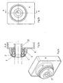
- FIGS. 1a and 1b show a sectional view and plan view of a part of a first device according to the invention with a solid shaft as a shaft.
- Figure 1c shows an associated 3D view.
- FIGS. 2a and 2b show sectional view and top view of a part of a device according to the invention with a hollow shaft as a shaft
- Figure 2c shows an associated 3D view.
- the driven shaft (1, 21) is connected to a second device, which is designed differently depending on the application.
- the shaft (1, 21) is mounted on the bearing 5 in the housing 6 of the device.
- the device is a torque at least passing or transmitting device. So this can be a gear, an adapter, a brake, a clutch or a motor.
- the second device fills at least the in FIG. 1a Dashed line area and thus pushes in the radial direction on the cap. 2
- the cap 2 rotates with the shaft (1, 21) and is firmly connected to the diverter ring 3 surrounded by it, for example welded.
- the diverter ring 3 is pressed at its largest diameter end to the housing 6 and travels along there.
- the construction, forces and materials in the present invention are dimensioned and selected so that the wear is not so strong that the function could not be guaranteed throughout the life of the first device.
- the protective cap 2 made of metal, so as to produce a stable and secure protection in a cost effective manner.
- the diverter ring 3 is electrically conductive and is advantageously made of a plastic, in particular of a graphite enriched Plastic, or a metal manufacturable. But there are also other materials usable, if they are at least electrically conductive and have low wear in the physical conditions occurring in the contact area on the housing 6 In particular, the temperature in the contact area is dependent on the speed of rotation of the shaft occurring thereley.Die rotational speed depends again from the largest diameter of the diverter 3 and the speed, the speed is determined by the application, so the operation and - type of the second device
- the essential purpose of the invention is the removal of static electricity, which may occur, for example, from the second device. Without the diverter ring 3 and / or the protective cap 2, the triboelectrically generated voltage would be applied to the shaft. This can lead to destruction and / or wear of components, in particular downstream components "
- the first device is designed as a transmission.
- the diverter ring prevents a triboelectrically caused voltage can build up, which would cause electrical currents in the transmission, which would flow from the shaft via a toothed part connected to this one or more intermeshing with this toothing toothing parts.
- the lubricant which is located between these toothing parts in their contact area, at least partially destroyed, in particular by splitting long molecules and / or accelerated oxidation processes,
- the housing of the gearbox is electrically connected to a motor housing, which is grounded, that is connected to ground ..
Landscapes
- Engineering & Computer Science (AREA)
- General Engineering & Computer Science (AREA)
- Mechanical Engineering (AREA)
- Power Engineering (AREA)
- Power Steering Mechanism (AREA)
- Motor Or Generator Frames (AREA)
- General Details Of Gearings (AREA)
- Steering Control In Accordance With Driving Conditions (AREA)
- Ultra Sonic Daignosis Equipment (AREA)
Description
- Die Erfindung betrifft eine Vorrichtung zum zumindest Durchleiten und/oder Übertragen von Drehmoment.
- Getriebe weisen eine abtriebsseitige Welle auf, die als Vollwelle oder Hohlwelle ausführbar ist und über mindestens ein Lager im Gehäuse des Getriebes gelagert ist
- Der Wirkungsgrad und die Lebensdauer des Getriebes ist wesentlich mitbestimmt durch den Schmierstoff zur Schmierung der Verzahnungsteile, dessen Alterung durch physikalische und/oder chemische Prozesse beeinflussbar ist.
- Aus der
US 5,812,908 ist ein elektrischer Kontakt für ein rotierendes Element benannt. - Aus der
EP 0 892 471 B1 ist ein Wälzlager mit Dichtung und elektrostatischer Entladungsschutzvorrichtung bekannt. - Aus der
US 6,142,673 ist ein Lager mit elektrischer Brücke bekannt. - Aus der
JP 59 170523 A - Aus der
US 4,530,609 ist ein Kugellager für ein conveyor (Fließband-Förderer) bekannt.. - Der Erfindung liegt daher die Aufgabe zugrunde, ein Getriebe zu schaffen, das kostengünstig herstellbar ist und eine hohe Lebensdauer bei möglichst vielen Anwendungen aufweist
- Erfindungsgemäß wird die Aufgabe bei dem Getriebe oder entsprechend artverwandten Vorrichtungen nach den in Anspruch 1 angegebenen Merkmalen gelöst.
- Wichtige Merkmale bei der Ersten Vorrichtung zum zumindest Durchleiten und/oder Übertragen von Drehmoment sind, dass sie eine Welle umfasst, die über zumindest ein Lager in einem Gehäuse der ersten Vorrichtung gelagert ist,
wobei eine zweite Vorrichtung mit der Welle lösbar verbindbar ist,
wobei das Gehäuse und die Welle über eine Komponente in elektrisch leitfähiger Verbindung stehen,
wobei mindestens einer der Kontaktbereiche zur Komponente ein ringlinienhafter Schleifkontakt ist,
wobei die Komponente aus nicht-isolierendem, also elektrisch leitfähigem Material ist,
wobei die Komponente als mit der Welle mitdrehender Ableitring ausgebildet ist, der Im Bereich seines größten Durchmessers einen ringlinienhaften Schleifkontakt zum Gehäuse aufweist
oder
die Komponente einen mit der Welle nicht-mitdrehenden Ableitring umfasst, der im Bereich seines kleinsten Durchmessers einen ringlinienhaften Schleifkontakt zur Welle aufweist,
wobei der Ableitring zumindest teilweise von einer Schutzkappe zum Schutz gegen mechanische Zerstörungen umgeben ist,
wobei die zweite Vorrichtung nach dem lösbaren Verbinden mit der Welle in axialer Richtung auf die Schutzkappe drückt,
wobei der Ableitring und die Schutzkappe derart fest verbunden sind, dass der Ableitring von der zweiten Vorrichtung mittels der Schutzkappe auf das Gehäuse in axialer Richtung gedrückt wird. - Vorteilig ist dabei, dass abtriebsseitig auftretende Spannungen abgebaut werden, indem die elektrischen Ladungen an das Gehäuse abgeleitet werden, das wiederum mit Masse verbindbar ist, also mit elektrischer Erde verbindbar ist. Die Masseverbindung ist dabei vorteiligerweise dadurch ausführbar, dass der verbundene Motor selbst mit elektrischer Erde verbunden ist. Da das Gehäuse der Vorrichtung und das Motorgehäuse aus Metall gefertigt sind, ist kein zusätzliches Teil zur Erdung des Gehäuses der Vorrichtung notwendig Wesentlich ist dabei aber, dass die Ströme nicht über das Innere des Getriebes, also über Verzahnungsteile, Lager und Schmierfilm, oder über das Innere der entsprechenden Vorrichtungen fließen, Somit sind diese Komponenten im Inneren der Vorrichtung geschützt.
- Der verwendete Schleifkontakt ist dabei sehr kostengünstig herstellbar.. Die so geschaffene elektrische Verbindung weist einen viel geringeren Widerstand von der Welle zum Gehäuse auf als der Widerstand über das Lager, über einen Wellendichtring samt Schmierfilm oder über die im Inneren sich befindenden Teile. Der letztgenannte Widerstand hängt ab von verschiedenen Betriebsfaktoren, wie Betriebstemperatur, insbesondere im Bereich des Schmierspaltes, Schmierölsorte, Lagersorte und dergleichen Er kann dabei im Widerstandswertebereich von Isolatoren liegen
- Bei einer bevorzugten Ausführung ist das Gehäuse mit elektrischer Masse verbunden, also elektrisch geerdet. Vorteilig ist dabei, dass sich keine Spannungen am Gehäuse aufbauen können und diese somit auch keine Gefährdung auslösen können.
- Erfindungsgemäß ist die Komponente aus nicht-isolierendem, also elektrisch leitfähigem Material. Vorteilig ist dabei, dass Material mit einer hohen elektrischen Leitfähigkeit wie Metall, aber auch Material mit einer nicht ganz so hohen Leitfähigkeit, wie beispielsweise mit Graphit dotierte Kunststoffe, verwendbar sind. Die Leitfähigkeit muss aber derart sein, dass die Ströme derart gut abgeleitet werden, dass sich keine wesentlichen Spannungswerte aufbauen, insbesondere also die Spannung kleiner als 1 Volt ist.
- Bei einer bevorzugten Ausführung weist die elektrische Verbindung von der Welle über die Komponente zum Gehäuse einen um mindestens eine Größenordnung niedrigeren Widerstand auf als der Widerstand, der der sonstigen Gesamtheit aller elektrischen Verbindungen zuordenbar ist, insbesondere nach Entfernen der Komponente. Vorteilig ist dabei, dass die im Inneren sich befindenden Komponenten geschützt sind, da nur ein äußerst geringer Anteil an Strom dort fließt. Insbesondere ist der Schmierstoff geschützt vor durch ihn hindurchfließenden elektrischen Strömen.
- Nach der Erfindung umfasst die Komponente einen mit der Welle mitdrehenden Ableitring, der im Bereich seines größten Durchmessers einen Schleifkontakt zum Gehäuse aufweist. Vorteilig ist dabei, dass ein Wellendichtring auf einem kleineren Durchmesser anbringbar ist und die Ströme trotzdem über den Schleifkontakt ableitbar sind an das Gehäuse - auch wenn hohe Relativgeschwindigkeiten auftreten.
- Die Komponente kann auch einen mit der Welle nichtmitdrehenden Ableitring umfassen, der im Bereich seines kleinsten Durchmessers einen Schleifkontakt zur Welle aufweist. Vorteilig ist dabei, dass die Relativgeschwindigkeiten gering sind und somit der Verschleiß gering ist.
- Erfindungsgemäß der Ableitring dabei mit der Schutzkappe fest verbunden. Vorteilig ist dabei, dass die zweite Vorrichtung nicht direkt auf den empfindlichen Ableitring drückt und dieser somit vor Zerstörung geschützt ist..
- Bei einer bevorzugten Ausführung berührt die zweite Vorrichtung die Schutzkappe und/oder den Ableitring und übt auf diese eine Kraft derart aus, dass eine Federspannung aufgebaut wird und der Ableitring mit dem Gehäuse in Kontakt gebracht wird. Vorteilig ist dabei, dass auch bei Verschleiß und dadurch bewirkten Verbrauch von Material des Ableitrings stets Material sozusagen nachgeführt wird und der Schleifkontakt somit funktionsfähig bleibt.
- Bei einer bevorzugten Ausführung ist die erste Vorrichtung ein Getriebe Vorteilig ist dabei, dass die Verzahnungsteile und der Schmierstoff geschützt sind.
- Weitere Vorteile ergeben sich aus den Unteransprüchen..
- Die Erfindung wird nun anhand von Abbildungen näher erläutert.
-
Figur 1a und 1b zeigen Schnittansicht und Draufsicht eines Teils einer erfindungsgemäßen ersten Vorrichtung mit Vollwelle als Welle.Figur 1c zeigt eine zugehörige 3D-Ansicht. -
Figur 2a und 2b zeigen Schnittansicht und Draufsicht eines Teils einer erfindungsgemäßen Vorrichtung mit Hohlwelle als WelleFigur 2c zeigt eine zugehörige 3D Ansicht. - Die abtreibende Welle (1, 21) wird mit einer zweiten Vorrichtung verbunden, die je nach Anwendung verschieden ausgeführt ist. Die Welle (1, 21) ist über das Lager 5 im Gehäuse 6 der Vorrichtung gelagert. Die Vorrichtung ist eine Drehmoment zumindest durchleitende oder übertragende Vorrichtung. Dies kann also ein Getriebe, ein Adapter, eine Bremse, eine Kupplung oder ein Motor sein.
- Die zweite Vorrichtung füllt zumindest den in
Figur 1a gestrichelt gezeichneten Bereich aus und drückt somit in radialer Richtung auf die Schutzkappe 2. - Die Schutzkappe 2 dreht mit der Welle (1, 21) mit und ist fest mit dem von ihr umgebenen Ableitring 3 verbunden, beispielsweise verschweißt. Somit wird der Ableitring 3 an seinem auf größtem Durchmesser liegenden Ende auf das Gehäuse 6 gedrückt und schleift dort entlang.
- Der Ableitring 3 verschleißt zwar, jedoch wird wegen der von der zweiten Vorrichtung ausgeübten Kraft eine Federspannung im Ableitring 3 bewirkt, die somit immer genügend viel Zustellung bewirkt, damit ein elektrisch wirksamer Schleifkontakt
- Die Konstruktion, die Kräfte und Materialien sind bei der vorliegenden Erfindung derart dimensioniert und ausgewählt, dass der Verschleiß nicht derart stark ist, dass die Funktion nicht über die gesamte Standzeit der ersten Vorrichtung gewährleistet werden könnte.
- Vorteiligerweise ist die Schutzkappe 2 aus Metall, um somit in kostengünstiger Weise einen stabilen und sicheren Schutz zu erzeugern. Der Ableitring 3 ist elektrisch leitend und ist vorteiligerweise aus einem Kunststoff, insbesondere aus einem mit Graphit angereicherten Kunststoff, oder einem Metall fertigbar. Es sind aber auch andere Materialien verwendbar, wenn sie zumindest elektrisch leitfähig sind und einen geringen Verschleiß bei den auftretenden physikalischen Bedingungen im Kontaktbereich am Gehäuse 6 aufweisen Insbesondere die Temperatur im Kontaktbereich ist dabei eine von der dort auftretenden Drehgeschwindigkeit der Welle abhängige Größe.Die Drehgeschwindigkeit hängt wiederum vom größten Durchmesser des Ableitrings 3 und der Drehzahl ab, wobei die Drehzahl bestimmt ist durch die Anwendung, also der Betriebsweise und - art der zweiten Vorrichtung
- Der wesentliche Zweck der Erfindung ist das Abbauen von Reibungselektrizität, die beispielsweise seitens der zweiten Vorrichtung auftreten kann. Ohne den Ableitring 3 und/oder die Schutzkappe 2 würde die reibungselektrisch erzeugte Spannung an der Welle anliegen. Dies kann zu Zerstörungen und/oder Verschleiß von Komponenten, insbesondere nachgeordneten Komponenten führen"
- Besonders vorteilhaft ist die erste Vorrichtung als Getriebe ausgeführt. Denn mittels des Ableitrings wird verhindert, dass sich eine reibungselektrisch verursachte Spannung aufbauen kann, die bei dem Getriebe elektrische Ströme verursachen würde, die von der Welle über ein mit dieser verbundenes Verzahnungsteil an ein oder mehrere mit diesem Verzahnungsteil im Eingriff stehende Verzahnungsteile fließen würden. Dabei würde nämlich das Schmiermittel, das zwischen diesen Verzahnungsteilen in deren Kontaktbereich sich befindet, zumindest teilweise zerstört, insbesondere durch Spalten langer Moleküle und/oder beschleunigter Oxidationsprozesse,
- Mittels der erfindungsgemäßen Ableitung der Ströme können diese aber keinen derartigen Schaden anrichten. Das Gehäuse des Getriebes ist mit einem Motorgehäuse elektrisch leitend verbunden, das geerdet ist, also mit Masse verbunden ist..
-
- 1
- Welle
- 2
- Schutzkappe
- 3
- Ableitring
- 4
- Wellendichtring
- 5
- Lager
- 6
- Gehäuse
- 21
- Hohlwelle
Claims (6)
- Erste Vorrichtung zum zumindest Durchleiten und/oder Übertragen von Drehmoment, umfassend eine Welle (1,21), die über zumindest ein Lager (5) in einem Gehäuse (6) der ersten Vorrichtung gelagert ist,
wobei eine zweite Vorrichtung mit der Welle (1,21) lösbar verbindbar ist,
wobei das Gehäuse (6) und die Welle (1,21) über eine Komponente (3) in elektrisch leitfähiger Verbindung stehen,
wobei mindestens einer der Kontaktbereiche zur Komponente (3) ein ringlinienhafter Schleifkontakt ist,
wobei die Komponente (3) aus nicht-Isolierendem, also elektrisch leitfähigem Material ist,
dadurch gekennzeichnet, dass die Komponente (3) als mit der Welle mitdrehender Ableitring (3) ausgebildet ist, der im Bereich seines größten Durchmessers einen ringlinienhaften Schleifkontakt zum Gehäuse (6) aufweist
oder
die Komponente (3) einen mit der Welle (1,21) nicht-mitdrehenden Ableitring (3) umfasst, der im Bereich seines kleinsten Durchmessers einen ringlinienhaften Schleifkontakt zur Welle (1,21) aufweist,
wobei der Ableitring (3) zumindest teilweise von einer Schutzkappe (2) zum Schutz gegen mechanische Zerstörungen umgeben ist,
wobei die zweite Vorrichtung so mit der Welle (1,21) lösbar verbindbar ist, dass sie in axialer Richtung auf die Schutzkappe (2) drückt,
wobei der Ableitring (3) und die Schutzkappe (2) derart fest verbunden sind, dass der Ableitring (3) von der zweiten Vorrichtung mittels der Schutzkappe (2) auf das Gehäuse (6) in axialer Richtung gedrückt wird. - Erste Vorrichtung nach Anspruch 1,
dadurch gekennzeichnet, dass
das Gehäuse (6) mit elektrischer Masse verbunden ist, also geerdet ist. - Erste Vorrichtung nach mindestens einem der vorangegangenen Ansprüche,
dadurch gekennzeichnet, dass
die elektrische Verbindung von der Welle (1,21) über die Komponente (3) zum Gehäuse (6) einen um mindestens eine Größenordnung niedrigeren Widerstand aufweist als der Widerstand, der den sonstigen Gesamtheit aller elektrischen Verbindungen zwischen Welle (1,21) und Gehäuse (6) zuordenbar ist, insbesondere nach Entfernen der Komponente (3), - Erste Vorrichtung nach mindestens einem der vorangegangenen Ansprüche,
dadurch gekennzeichnet, dass
die zweite Vorrichtung die Schutzkappe und/oder den Ableitring berührt und auf diese eine Kraft derart ausübt, dass eine Federspannung aufgebaut wird und der Ableitring mit dem Gehäuse (6) in Kontakt gebracht wird. - Erste Vorrichtung nach mindestens einem der vorangegangenen Ansprüche,
dadurch gekennzeichnet, dass
die erste Vorrichtung eine Kupplung, ein Adapter, eine Bremse oder ein Elektromotor ist. - Erste Vorrichtung nach mindestens einem der vorangegangenen Ansprüche,
dadurch gekennzeichnet, dass
die erste Vorrichtung ein Getriebe ist.
Applications Claiming Priority (3)
| Application Number | Priority Date | Filing Date | Title |
|---|---|---|---|
| DE10249770A DE10249770B4 (de) | 2002-10-24 | 2002-10-24 | Getriebe |
| DE10249770 | 2002-10-24 | ||
| PCT/EP2003/009843 WO2004038241A1 (de) | 2002-10-24 | 2003-09-05 | Vorrichtung zum zumindest durchleiten und/oder übertragen von drehmoment |
Publications (2)
| Publication Number | Publication Date |
|---|---|
| EP1556624A1 EP1556624A1 (de) | 2005-07-27 |
| EP1556624B1 true EP1556624B1 (de) | 2008-12-17 |
Family
ID=32114862
Family Applications (1)
| Application Number | Title | Priority Date | Filing Date |
|---|---|---|---|
| EP03809262A Expired - Lifetime EP1556624B1 (de) | 2002-10-24 | 2003-09-05 | Vorrichtung zum zumindest durchleiten und/oder übertragen von drehmoment |
Country Status (5)
| Country | Link |
|---|---|
| EP (1) | EP1556624B1 (de) |
| AT (1) | ATE418017T1 (de) |
| AU (1) | AU2003264267A1 (de) |
| DE (2) | DE10249770B4 (de) |
| WO (1) | WO2004038241A1 (de) |
Cited By (1)
| Publication number | Priority date | Publication date | Assignee | Title |
|---|---|---|---|---|
| DE102014112561A1 (de) * | 2014-09-01 | 2016-03-03 | Cw Bearing Gmbh | Wälzlager mit elektrischem Bypass für Wälzkörper |
Families Citing this family (12)
| Publication number | Priority date | Publication date | Assignee | Title |
|---|---|---|---|---|
| US8010060B2 (en) * | 2007-08-29 | 2011-08-30 | GM Global Technology Operations LLC | Apparatus and method for reducing stray RF signal noise in an electrically powered vehicle |
| US8186686B2 (en) | 2009-04-29 | 2012-05-29 | GM Global Technology Operations LLC | Electrically-conductive seal assembly |
| DE102012213920A1 (de) * | 2012-08-06 | 2014-02-06 | Voith Patent Gmbh | Getriebebaueinheit und Antriebseinheit mit einer Getriebebaueinheit |
| DE102012219819A1 (de) * | 2012-10-30 | 2014-04-30 | Voith Patent Gmbh | Getriebebaueinheit und Antriebsstrang mit einer Getriebebaueinheit |
| DE102013223673B4 (de) * | 2013-11-20 | 2021-10-07 | Zf Friedrichshafen Ag | Kraftfahrzeugantriebsstrang |
| DE102014018449B3 (de) * | 2014-12-12 | 2016-06-09 | Audi Ag | Elektrische Maschine |
| DE102015218521A1 (de) * | 2015-09-25 | 2016-09-29 | Magna powertrain gmbh & co kg | Elektrische Maschine |
| US11637477B2 (en) * | 2019-01-02 | 2023-04-25 | Joseph Gentile | Rotating machine |
| DE102019207241A1 (de) | 2019-05-17 | 2020-11-19 | Zf Friedrichshafen Ag | Vorrichtung zur elektrisch leitfähigen Verbindung zwischen einer Welle und einem Gehäuse |
| DE102020212587A1 (de) | 2020-10-06 | 2022-04-07 | Zf Friedrichshafen Ag | Getriebe und elektrischer Achsantrieb für ein Kraftfahrzeug |
| DE102020212588A1 (de) | 2020-10-06 | 2022-04-07 | Zf Friedrichshafen Ag | Getriebe für ein Kraftfahrzeug, sowie elektrischer Achsantrieb |
| DE102020212589A1 (de) | 2020-10-06 | 2022-04-07 | Zf Friedrichshafen Ag | Wellenerdungs-Anordnung, Getriebe, und elektrischer Achsantrieb |
Family Cites Families (10)
| Publication number | Priority date | Publication date | Assignee | Title |
|---|---|---|---|---|
| JPS59170523A (ja) * | 1983-03-16 | 1984-09-26 | Hitachi Ltd | 電動機 |
| US4530609A (en) * | 1983-08-03 | 1985-07-23 | Frocemco, Inc. | Conveyor roll bearing |
| DE4221403C2 (de) * | 1992-06-30 | 1995-08-31 | Kaltenbach & Voigt | Ärztliches oder zahnärztliches Behandlungsinstrument mit einem angetriebenem Behandlungswerkzeug |
| US5812908A (en) * | 1997-03-25 | 1998-09-22 | Xerox Corporation | Carbon fiber electrical contact mounting for rotating elements |
| IT1293461B1 (it) * | 1997-07-17 | 1999-03-01 | Skf Ind Spa | Cuscinetto di rotolamento con dispositivo di tenuta e di scarico di correnti elettrostatiche. |
| DE19824022C2 (de) * | 1998-05-29 | 2003-10-30 | Skf Gmbh | Wälzlager mit Strombrücke |
| DE19920384C1 (de) * | 1999-05-04 | 2000-08-03 | Stemmann Technik Gmbh | Erdungskontakt |
| DE20007714U1 (de) * | 2000-05-01 | 2001-09-13 | Rasch, Jürgen, 47877 Willich | Vorrichtung zum Schutz der Lage einer dynamoelektrischen Maschine |
| US20020121821A1 (en) * | 2001-03-02 | 2002-09-05 | Ritter Allen Michael | Method and apparatus for reducing bearing current in a motor and/or generator |
| DE20106984U1 (de) * | 2001-03-24 | 2001-09-13 | Karstädt, Lutz, 28213 Bremen | Strom-Schutz-Scheibe |
-
2002
- 2002-10-24 DE DE10249770A patent/DE10249770B4/de not_active Expired - Lifetime
-
2003
- 2003-09-05 AT AT03809262T patent/ATE418017T1/de not_active IP Right Cessation
- 2003-09-05 DE DE50310943T patent/DE50310943D1/de not_active Expired - Lifetime
- 2003-09-05 WO PCT/EP2003/009843 patent/WO2004038241A1/de not_active Ceased
- 2003-09-05 EP EP03809262A patent/EP1556624B1/de not_active Expired - Lifetime
- 2003-09-05 AU AU2003264267A patent/AU2003264267A1/en not_active Abandoned
Cited By (1)
| Publication number | Priority date | Publication date | Assignee | Title |
|---|---|---|---|---|
| DE102014112561A1 (de) * | 2014-09-01 | 2016-03-03 | Cw Bearing Gmbh | Wälzlager mit elektrischem Bypass für Wälzkörper |
Also Published As
| Publication number | Publication date |
|---|---|
| EP1556624A1 (de) | 2005-07-27 |
| WO2004038241A1 (de) | 2004-05-06 |
| DE10249770B4 (de) | 2005-11-03 |
| DE50310943D1 (de) | 2009-01-29 |
| AU2003264267A1 (en) | 2004-05-13 |
| ATE418017T1 (de) | 2009-01-15 |
| DE10249770A1 (de) | 2004-05-19 |
Similar Documents
| Publication | Publication Date | Title |
|---|---|---|
| EP1556624B1 (de) | Vorrichtung zum zumindest durchleiten und/oder übertragen von drehmoment | |
| DE102020119719B4 (de) | Ableitvorrichtung für eine elektrische Maschine sowie elektrische Maschine mit der Ableitvorrichtung | |
| EP3387293B1 (de) | Spannungswellengetriebe mit innendichtung | |
| EP2981746B1 (de) | Gleitringdichtungsanordnung mit unterschiedlich harten gleitflächen | |
| EP1544504B1 (de) | Planetengetriebe für Windkraftanlagen | |
| DE19805566B4 (de) | Wälzlagerung für Schienenfahrzeuge mit Stromdurchgang | |
| EP3387298A1 (de) | Dichtung | |
| DE102020104957A1 (de) | Erdung für ein Getriebe | |
| DE102019112825A1 (de) | Adaptionsblech für Wälzlager mit integrierter Stromableitung | |
| DE102016106996A1 (de) | Dichtungsanordnung für eine Welle | |
| DE102021002928A1 (de) | Getriebe mit einer Welle und einem Gehäuseteil | |
| DE102023100830B3 (de) | Gleitringdichtungsanordnung | |
| EP2491641B1 (de) | Elektrische maschine, hydraulikeinheit | |
| DE102022101754B4 (de) | Elektrische Rotationsmaschine, elektrisches Antriebssystem und Getriebemotoreinheit | |
| WO2023227156A1 (de) | Ableitvorrichtung zur ableitung einer elektrischen ladung und/oder spannung über eine welle eines antriebsstrangs sowie ein antriebsstrang mit der ableitvorrichtung | |
| DE102022113004A1 (de) | Wälzlagervorrichtung | |
| DE102006017443B4 (de) | Wälzlageranordnung | |
| EP1741942A2 (de) | Lagerung einer Welle eines Kegelrades | |
| WO2022073548A1 (de) | Dichtungsanordnung für radlager und radlagereinheit mit dichtungsanordnung | |
| DE102023209795B3 (de) | Erdungsvorrichtung | |
| DE102021112953A1 (de) | Ringförmige Sensoranordnung | |
| DE102023100863B3 (de) | Gleitringdichtungsanordnung | |
| DE102024104018B4 (de) | Wälzlageranordnung | |
| DE102019118890A1 (de) | Lager | |
| DE102017128360A1 (de) | Elektromotorische Antriebseinheit |
Legal Events
| Date | Code | Title | Description |
|---|---|---|---|
| PUAI | Public reference made under article 153(3) epc to a published international application that has entered the european phase |
Free format text: ORIGINAL CODE: 0009012 |
|
| 17P | Request for examination filed |
Effective date: 20050524 |
|
| AK | Designated contracting states |
Kind code of ref document: A1 Designated state(s): AT BE BG CH CY CZ DE DK EE ES FI FR GB GR HU IE IT LI LU MC NL PT RO SE SI SK TR |
|
| AX | Request for extension of the european patent |
Extension state: AL LT LV MK |
|
| DAX | Request for extension of the european patent (deleted) | ||
| 17Q | First examination report despatched |
Effective date: 20070618 |
|
| GRAP | Despatch of communication of intention to grant a patent |
Free format text: ORIGINAL CODE: EPIDOSNIGR1 |
|
| RAP1 | Party data changed (applicant data changed or rights of an application transferred) |
Owner name: SEW-EURODRIVE GMBH & CO |
|
| GRAS | Grant fee paid |
Free format text: ORIGINAL CODE: EPIDOSNIGR3 |
|
| GRAA | (expected) grant |
Free format text: ORIGINAL CODE: 0009210 |
|
| AK | Designated contracting states |
Kind code of ref document: B1 Designated state(s): AT BE BG CH CY CZ DE DK EE ES FI FR GB GR HU IE IT LI LU MC NL PT RO SE SI SK TR |
|
| REG | Reference to a national code |
Ref country code: GB Ref legal event code: FG4D Free format text: NOT ENGLISH |
|
| REG | Reference to a national code |
Ref country code: CH Ref legal event code: EP |
|
| REG | Reference to a national code |
Ref country code: IE Ref legal event code: FG4D Free format text: LANGUAGE OF EP DOCUMENT: GERMAN |
|
| REF | Corresponds to: |
Ref document number: 50310943 Country of ref document: DE Date of ref document: 20090129 Kind code of ref document: P |
|
| PG25 | Lapsed in a contracting state [announced via postgrant information from national office to epo] |
Ref country code: SI Free format text: LAPSE BECAUSE OF FAILURE TO SUBMIT A TRANSLATION OF THE DESCRIPTION OR TO PAY THE FEE WITHIN THE PRESCRIBED TIME-LIMIT Effective date: 20081217 Ref country code: FI Free format text: LAPSE BECAUSE OF FAILURE TO SUBMIT A TRANSLATION OF THE DESCRIPTION OR TO PAY THE FEE WITHIN THE PRESCRIBED TIME-LIMIT Effective date: 20081217 Ref country code: NL Free format text: LAPSE BECAUSE OF FAILURE TO SUBMIT A TRANSLATION OF THE DESCRIPTION OR TO PAY THE FEE WITHIN THE PRESCRIBED TIME-LIMIT Effective date: 20081217 |
|
| NLV1 | Nl: lapsed or annulled due to failure to fulfill the requirements of art. 29p and 29m of the patents act | ||
| REG | Reference to a national code |
Ref country code: IE Ref legal event code: FD4D |
|
| PG25 | Lapsed in a contracting state [announced via postgrant information from national office to epo] |
Ref country code: ES Free format text: LAPSE BECAUSE OF FAILURE TO SUBMIT A TRANSLATION OF THE DESCRIPTION OR TO PAY THE FEE WITHIN THE PRESCRIBED TIME-LIMIT Effective date: 20090328 Ref country code: EE Free format text: LAPSE BECAUSE OF FAILURE TO SUBMIT A TRANSLATION OF THE DESCRIPTION OR TO PAY THE FEE WITHIN THE PRESCRIBED TIME-LIMIT Effective date: 20081217 Ref country code: IE Free format text: LAPSE BECAUSE OF FAILURE TO SUBMIT A TRANSLATION OF THE DESCRIPTION OR TO PAY THE FEE WITHIN THE PRESCRIBED TIME-LIMIT Effective date: 20081217 Ref country code: BG Free format text: LAPSE BECAUSE OF FAILURE TO SUBMIT A TRANSLATION OF THE DESCRIPTION OR TO PAY THE FEE WITHIN THE PRESCRIBED TIME-LIMIT Effective date: 20090317 Ref country code: RO Free format text: LAPSE BECAUSE OF FAILURE TO SUBMIT A TRANSLATION OF THE DESCRIPTION OR TO PAY THE FEE WITHIN THE PRESCRIBED TIME-LIMIT Effective date: 20081217 |
|
| PG25 | Lapsed in a contracting state [announced via postgrant information from national office to epo] |
Ref country code: CZ Free format text: LAPSE BECAUSE OF FAILURE TO SUBMIT A TRANSLATION OF THE DESCRIPTION OR TO PAY THE FEE WITHIN THE PRESCRIBED TIME-LIMIT Effective date: 20081217 Ref country code: PT Free format text: LAPSE BECAUSE OF FAILURE TO SUBMIT A TRANSLATION OF THE DESCRIPTION OR TO PAY THE FEE WITHIN THE PRESCRIBED TIME-LIMIT Effective date: 20090518 Ref country code: SE Free format text: LAPSE BECAUSE OF FAILURE TO SUBMIT A TRANSLATION OF THE DESCRIPTION OR TO PAY THE FEE WITHIN THE PRESCRIBED TIME-LIMIT Effective date: 20090317 |
|
| PG25 | Lapsed in a contracting state [announced via postgrant information from national office to epo] |
Ref country code: SK Free format text: LAPSE BECAUSE OF FAILURE TO SUBMIT A TRANSLATION OF THE DESCRIPTION OR TO PAY THE FEE WITHIN THE PRESCRIBED TIME-LIMIT Effective date: 20081217 |
|
| PLBE | No opposition filed within time limit |
Free format text: ORIGINAL CODE: 0009261 |
|
| STAA | Information on the status of an ep patent application or granted ep patent |
Free format text: STATUS: NO OPPOSITION FILED WITHIN TIME LIMIT |
|
| PG25 | Lapsed in a contracting state [announced via postgrant information from national office to epo] |
Ref country code: DK Free format text: LAPSE BECAUSE OF FAILURE TO SUBMIT A TRANSLATION OF THE DESCRIPTION OR TO PAY THE FEE WITHIN THE PRESCRIBED TIME-LIMIT Effective date: 20081217 |
|
| 26N | No opposition filed |
Effective date: 20090918 |
|
| BERE | Be: lapsed |
Owner name: SEW-EURODRIVE G.M.B.H. & CO Effective date: 20090930 |
|
| PG25 | Lapsed in a contracting state [announced via postgrant information from national office to epo] |
Ref country code: MC Free format text: LAPSE BECAUSE OF NON-PAYMENT OF DUE FEES Effective date: 20090930 |
|
| REG | Reference to a national code |
Ref country code: CH Ref legal event code: PL |
|
| PG25 | Lapsed in a contracting state [announced via postgrant information from national office to epo] |
Ref country code: BE Free format text: LAPSE BECAUSE OF NON-PAYMENT OF DUE FEES Effective date: 20090930 |
|
| PG25 | Lapsed in a contracting state [announced via postgrant information from national office to epo] |
Ref country code: LI Free format text: LAPSE BECAUSE OF NON-PAYMENT OF DUE FEES Effective date: 20090930 Ref country code: GR Free format text: LAPSE BECAUSE OF FAILURE TO SUBMIT A TRANSLATION OF THE DESCRIPTION OR TO PAY THE FEE WITHIN THE PRESCRIBED TIME-LIMIT Effective date: 20090318 Ref country code: CH Free format text: LAPSE BECAUSE OF NON-PAYMENT OF DUE FEES Effective date: 20090930 |
|
| PG25 | Lapsed in a contracting state [announced via postgrant information from national office to epo] |
Ref country code: AT Free format text: LAPSE BECAUSE OF NON-PAYMENT OF DUE FEES Effective date: 20090905 |
|
| PG25 | Lapsed in a contracting state [announced via postgrant information from national office to epo] |
Ref country code: IT Free format text: LAPSE BECAUSE OF FAILURE TO SUBMIT A TRANSLATION OF THE DESCRIPTION OR TO PAY THE FEE WITHIN THE PRESCRIBED TIME-LIMIT Effective date: 20081217 |
|
| PG25 | Lapsed in a contracting state [announced via postgrant information from national office to epo] |
Ref country code: LU Free format text: LAPSE BECAUSE OF NON-PAYMENT OF DUE FEES Effective date: 20090905 |
|
| PG25 | Lapsed in a contracting state [announced via postgrant information from national office to epo] |
Ref country code: HU Free format text: LAPSE BECAUSE OF FAILURE TO SUBMIT A TRANSLATION OF THE DESCRIPTION OR TO PAY THE FEE WITHIN THE PRESCRIBED TIME-LIMIT Effective date: 20090618 |
|
| PG25 | Lapsed in a contracting state [announced via postgrant information from national office to epo] |
Ref country code: TR Free format text: LAPSE BECAUSE OF FAILURE TO SUBMIT A TRANSLATION OF THE DESCRIPTION OR TO PAY THE FEE WITHIN THE PRESCRIBED TIME-LIMIT Effective date: 20081217 |
|
| PG25 | Lapsed in a contracting state [announced via postgrant information from national office to epo] |
Ref country code: CY Free format text: LAPSE BECAUSE OF FAILURE TO SUBMIT A TRANSLATION OF THE DESCRIPTION OR TO PAY THE FEE WITHIN THE PRESCRIBED TIME-LIMIT Effective date: 20081217 |
|
| REG | Reference to a national code |
Ref country code: FR Ref legal event code: PLFP Year of fee payment: 14 |
|
| REG | Reference to a national code |
Ref country code: FR Ref legal event code: PLFP Year of fee payment: 15 |
|
| REG | Reference to a national code |
Ref country code: FR Ref legal event code: PLFP Year of fee payment: 16 |
|
| PGFP | Annual fee paid to national office [announced via postgrant information from national office to epo] |
Ref country code: GB Payment date: 20220804 Year of fee payment: 20 Ref country code: DE Payment date: 20220930 Year of fee payment: 20 |
|
| PGFP | Annual fee paid to national office [announced via postgrant information from national office to epo] |
Ref country code: FR Payment date: 20220808 Year of fee payment: 20 |
|
| REG | Reference to a national code |
Ref country code: DE Ref legal event code: R071 Ref document number: 50310943 Country of ref document: DE |
|
| REG | Reference to a national code |
Ref country code: GB Ref legal event code: PE20 Expiry date: 20230904 |
|
| PG25 | Lapsed in a contracting state [announced via postgrant information from national office to epo] |
Ref country code: GB Free format text: LAPSE BECAUSE OF EXPIRATION OF PROTECTION Effective date: 20230904 |