EP1556624B1 - Dispositif servant au moins a transferer et/ou transmettre un couple - Google Patents
Dispositif servant au moins a transferer et/ou transmettre un couple Download PDFInfo
- Publication number
- EP1556624B1 EP1556624B1 EP03809262A EP03809262A EP1556624B1 EP 1556624 B1 EP1556624 B1 EP 1556624B1 EP 03809262 A EP03809262 A EP 03809262A EP 03809262 A EP03809262 A EP 03809262A EP 1556624 B1 EP1556624 B1 EP 1556624B1
- Authority
- EP
- European Patent Office
- Prior art keywords
- shaft
- housing
- component
- protective cap
- discharge ring
- Prior art date
- Legal status (The legal status is an assumption and is not a legal conclusion. Google has not performed a legal analysis and makes no representation as to the accuracy of the status listed.)
- Expired - Lifetime
Links
- 230000002463 transducing effect Effects 0.000 title abstract 2
- 230000001681 protective effect Effects 0.000 claims description 14
- 230000005540 biological transmission Effects 0.000 claims description 10
- 239000000463 material Substances 0.000 claims description 7
- 230000006378 damage Effects 0.000 claims description 5
- 239000000314 lubricant Substances 0.000 description 5
- 239000002184 metal Substances 0.000 description 4
- 230000001050 lubricating effect Effects 0.000 description 3
- 239000004033 plastic Substances 0.000 description 3
- 229920003023 plastic Polymers 0.000 description 3
- 239000004020 conductor Substances 0.000 description 2
- 230000005611 electricity Effects 0.000 description 2
- 239000007787 solid Substances 0.000 description 2
- OKTJSMMVPCPJKN-UHFFFAOYSA-N Carbon Chemical compound [C] OKTJSMMVPCPJKN-UHFFFAOYSA-N 0.000 description 1
- 230000032683 aging Effects 0.000 description 1
- 238000001311 chemical methods and process Methods 0.000 description 1
- 238000010276 construction Methods 0.000 description 1
- 230000007797 corrosion Effects 0.000 description 1
- 238000005260 corrosion Methods 0.000 description 1
- 230000001419 dependent effect Effects 0.000 description 1
- 238000009795 derivation Methods 0.000 description 1
- 238000007599 discharging Methods 0.000 description 1
- 229910002804 graphite Inorganic materials 0.000 description 1
- 239000010439 graphite Substances 0.000 description 1
- 239000012212 insulator Substances 0.000 description 1
- 239000010687 lubricating oil Substances 0.000 description 1
- 238000000034 method Methods 0.000 description 1
- 230000003647 oxidation Effects 0.000 description 1
- 238000007254 oxidation reaction Methods 0.000 description 1
- 238000005096 rolling process Methods 0.000 description 1
- 230000003068 static effect Effects 0.000 description 1
- 230000035882 stress Effects 0.000 description 1
Images

Classifications
-
- F—MECHANICAL ENGINEERING; LIGHTING; HEATING; WEAPONS; BLASTING
- F16—ENGINEERING ELEMENTS AND UNITS; GENERAL MEASURES FOR PRODUCING AND MAINTAINING EFFECTIVE FUNCTIONING OF MACHINES OR INSTALLATIONS; THERMAL INSULATION IN GENERAL
- F16C—SHAFTS; FLEXIBLE SHAFTS; ELEMENTS OR CRANKSHAFT MECHANISMS; ROTARY BODIES OTHER THAN GEARING ELEMENTS; BEARINGS
- F16C19/00—Bearings with rolling contact, for exclusively rotary movement
- F16C19/52—Bearings with rolling contact, for exclusively rotary movement with devices affected by abnormal or undesired conditions
-
- F—MECHANICAL ENGINEERING; LIGHTING; HEATING; WEAPONS; BLASTING
- F16—ENGINEERING ELEMENTS AND UNITS; GENERAL MEASURES FOR PRODUCING AND MAINTAINING EFFECTIVE FUNCTIONING OF MACHINES OR INSTALLATIONS; THERMAL INSULATION IN GENERAL
- F16C—SHAFTS; FLEXIBLE SHAFTS; ELEMENTS OR CRANKSHAFT MECHANISMS; ROTARY BODIES OTHER THAN GEARING ELEMENTS; BEARINGS
- F16C41/00—Other accessories, e.g. devices integrated in the bearing not relating to the bearing function as such
- F16C41/002—Conductive elements, e.g. to prevent static electricity
-
- H—ELECTRICITY
- H02—GENERATION; CONVERSION OR DISTRIBUTION OF ELECTRIC POWER
- H02K—DYNAMO-ELECTRIC MACHINES
- H02K11/00—Structural association of dynamo-electric machines with electric components or with devices for shielding, monitoring or protection
- H02K11/40—Structural association with grounding devices
-
- H—ELECTRICITY
- H02—GENERATION; CONVERSION OR DISTRIBUTION OF ELECTRIC POWER
- H02K—DYNAMO-ELECTRIC MACHINES
- H02K5/00—Casings; Enclosures; Supports
- H02K5/04—Casings or enclosures characterised by the shape, form or construction thereof
- H02K5/16—Means for supporting bearings, e.g. insulating supports or means for fitting bearings in the bearing-shields
- H02K5/173—Means for supporting bearings, e.g. insulating supports or means for fitting bearings in the bearing-shields using bearings with rolling contact, e.g. ball bearings
- H02K5/1732—Means for supporting bearings, e.g. insulating supports or means for fitting bearings in the bearing-shields using bearings with rolling contact, e.g. ball bearings radially supporting the rotary shaft at both ends of the rotor
Definitions
- the invention relates to a device for at least passing through and / or transmitting torque.
- Transmissions have an output-side shaft, which can be executed as a solid shaft or hollow shaft and is mounted via at least one bearing in the housing of the transmission
- the efficiency and service life of the transmission is significantly influenced by the lubricant for lubricating the teeth, the aging of which can be influenced by physical and / or chemical processes.
- the invention is therefore based on the object to provide a transmission which is inexpensive to produce and has a long service life in as many applications
- the object is achieved in the transmission or correspondingly related devices according to the features indicated in claim 1.
- the first device for at least passing through and / or transmitting torque comprises a shaft which is mounted via at least one bearing in a housing of the first device, wherein a second device is detachably connectable to the shaft, wherein the housing and the shaft are in an electrically conductive connection via a component, wherein at least one of the contact areas to the component is an annular sliding contact, wherein the component is made of non-insulating, ie electrically conductive material, wherein the component is formed as a co-rotating with the diverting ring, which has an annular sliding contact with the housing in the region of its largest diameter or the component comprises a diverter ring which does not rotate with the shaft and which has an annular sliding contact with the shaft in the region of its smallest diameter, wherein the diverter ring is at least partially surrounded by a protective cap for protection against mechanical damage, wherein the second device presses on the protective cap in the axial direction after detachable connection with the shaft, wherein the diverter ring and the protective cap are
- the sliding contact used is very inexpensive to produce ..
- the electrical connection thus created has a much lower resistance from the shaft to the housing than the resistance of the bearing, a shaft seal including lubricant film or on the inside are located parts.
- the latter resistance depends on various operating factors, such as operating temperature, in particular in the region of the lubricating gap, type of lubricating oil, storage location and the like. It may be in the resistance value range of insulators
- the housing is connected to electrical ground, that is electrically grounded.
- the component is made of non-insulating, ie electrically conductive material. It is advantageous that material with a high electrical conductivity such as metal, but also material with a not so high conductivity, such as graphite-doped plastics, are usable. However, the conductivity must be such that the currents are dissipated so well that build up no significant voltage values, in particular so that the voltage is less than 1 volt.
- the electrical connection from the shaft via the component to the housing by at least an order of magnitude lower resistance than the resistance, which is the other entirety of all electrical connections can be assigned, in particular after removal of the component. It is advantageous in this case that the components located in the interior are protected, since only one extremely low proportion of electricity flows there. In particular, the lubricant is protected from passing through him electrical currents.
- the component comprises a co-rotating with the shaft diverter, which has a sliding contact with the housing in the region of its largest diameter. It is advantageous that a shaft seal on a smaller diameter can be attached and the currents are still derivable via the sliding contact to the housing - even if high relative velocities occur.
- the component may also comprise a diverter ring not rotating with the shaft, which has a sliding contact with the shaft in the region of its smallest diameter.
- the advantage here is that the relative speeds are low and thus the wear is low.
- the diverting ring firmly connected to the protective cap.
- the advantage here is that the second device does not press directly on the sensitive diverter ring and this is thus protected from destruction.
- the second device contacts the protective cap and / or the diverter ring and exerts a force on it such that a spring tension is built up and the diverting ring is brought into contact with the housing.
- the first device is a transmission It is advantageous in this case that the toothing parts and the lubricant are protected.
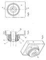
- FIGS. 1a and 1b show a sectional view and plan view of a part of a first device according to the invention with a solid shaft as a shaft.
- Figure 1c shows an associated 3D view.
- FIGS. 2a and 2b show sectional view and top view of a part of a device according to the invention with a hollow shaft as a shaft
- Figure 2c shows an associated 3D view.
- the driven shaft (1, 21) is connected to a second device, which is designed differently depending on the application.
- the shaft (1, 21) is mounted on the bearing 5 in the housing 6 of the device.
- the device is a torque at least passing or transmitting device. So this can be a gear, an adapter, a brake, a clutch or a motor.
- the second device fills at least the in FIG. 1a Dashed line area and thus pushes in the radial direction on the cap. 2
- the cap 2 rotates with the shaft (1, 21) and is firmly connected to the diverter ring 3 surrounded by it, for example welded.
- the diverter ring 3 is pressed at its largest diameter end to the housing 6 and travels along there.
- the construction, forces and materials in the present invention are dimensioned and selected so that the wear is not so strong that the function could not be guaranteed throughout the life of the first device.
- the protective cap 2 made of metal, so as to produce a stable and secure protection in a cost effective manner.
- the diverter ring 3 is electrically conductive and is advantageously made of a plastic, in particular of a graphite enriched Plastic, or a metal manufacturable. But there are also other materials usable, if they are at least electrically conductive and have low wear in the physical conditions occurring in the contact area on the housing 6 In particular, the temperature in the contact area is dependent on the speed of rotation of the shaft occurring thereley.Die rotational speed depends again from the largest diameter of the diverter 3 and the speed, the speed is determined by the application, so the operation and - type of the second device
- the essential purpose of the invention is the removal of static electricity, which may occur, for example, from the second device. Without the diverter ring 3 and / or the protective cap 2, the triboelectrically generated voltage would be applied to the shaft. This can lead to destruction and / or wear of components, in particular downstream components "
- the first device is designed as a transmission.
- the diverter ring prevents a triboelectrically caused voltage can build up, which would cause electrical currents in the transmission, which would flow from the shaft via a toothed part connected to this one or more intermeshing with this toothing toothing parts.
- the lubricant which is located between these toothing parts in their contact area, at least partially destroyed, in particular by splitting long molecules and / or accelerated oxidation processes,
- the housing of the gearbox is electrically connected to a motor housing, which is grounded, that is connected to ground ..
Landscapes
- Engineering & Computer Science (AREA)
- General Engineering & Computer Science (AREA)
- Mechanical Engineering (AREA)
- Power Engineering (AREA)
- Power Steering Mechanism (AREA)
- Motor Or Generator Frames (AREA)
- General Details Of Gearings (AREA)
- Steering Control In Accordance With Driving Conditions (AREA)
- Ultra Sonic Daignosis Equipment (AREA)
Claims (6)
- Premier dispositif servant au moins à transférer et/ou à transmettre un couple, comprenant un arbre (1, 21) qui est monté au moyen d'au moins un palier (5) dans un boîtier (6) du premier dispositif,
sachant qu'un deuxième dispositif peut être assemblé de manière amovible à l'arbre (1, 21),
sachant que le boîtier (6) et l'arbre (1, 21) se trouvent en liaison électriquement conductrice par l'intermédiaire d'un élément (3),
sachant qu'au moins une des régions de contact vers l'élément (3) est un contact frotteur annulairement linéaire,
sachant que l'élément (3) est constitué d'un matériau non isolant, donc électriquement conducteur,
caractérisé en ce que l'élément (3) est réalisé sous la forme d'une bague de dissipation (3) tournant conjointement avec l'arbre, laquelle présente dans la région de son plus grand diamètre un contact frotteur linéairement annulaire vers le boîtier (6),
ou
l'élément (3) comprend une bague de dissipation (3) ne tournant pas conjointement avec l'arbre (1, 21), laquelle présente dans la région de son plus petit diamètre un contact frotteur linéairement annulaire vers l'arbre (1, 21),
sachant que la bague de dissipation (3) est entourée au moins partiellement par un capuchon de protection (2) pour la protéger des dégradations mécaniques,
sachant que le deuxième dispositif peut être assemblé de manière amovible à l'arbre (1, 21) de telle sorte qu'il exerce une pression en direction axiale sur le capuchon de protection (2),
sachant que la bague de dissipation (3) et le capuchon de protection (2) sont fixement assemblés de telle sorte que la bague de dissipation (3) est pressée par le deuxième dispositif, par l'intermédiaire du capuchon de protection (2), en direction axiale sur le boîtier (6). - Premier dispositif selon la revendication 1, caractérisé en ce que le boîtier (6) est relié à une masse électrique, donc est mis à la terre.
- Premier dispositif selon au moins une des revendications précédentes, caractérisé en ce que la liaison électrique de l'arbre (1, 21) au boîtier (6) par l'intermédiaire de l'élément (3) présente une résistance inférieure d'au moins un ordre de grandeur à la résistance qui peut être autrement associée à l'ensemble de toutes les liaisons électriques entre l'arbre (1, 21) et le boîtier (6), notamment après enlèvement de l'élément (3).
- Premier dispositif selon au moins une des revendications précédentes, caractérisé en ce que le deuxième dispositif est en contact physique avec le capuchon de protection et/ou la bague de dissipation et exerce sur eux une force de telle sorte qu'une contrainte de ressort est établie et que la bague de dissipation est amenée en contact avec le boîtier (6).
- Premier dispositif selon au moins une des revendications précédentes, caractérisé en ce que le premier dispositif est un accouplement, un adaptateur, un frein ou un moteur électrique.
- Premier dispositif selon au moins une des revendications précédentes, caractérisé en ce que le premier dispositif est un mécanisme de transmission.
Applications Claiming Priority (3)
| Application Number | Priority Date | Filing Date | Title |
|---|---|---|---|
| DE10249770A DE10249770B4 (de) | 2002-10-24 | 2002-10-24 | Getriebe |
| DE10249770 | 2002-10-24 | ||
| PCT/EP2003/009843 WO2004038241A1 (fr) | 2002-10-24 | 2003-09-05 | Dispositif servant au moins a transferer et/ou transmettre un couple |
Publications (2)
| Publication Number | Publication Date |
|---|---|
| EP1556624A1 EP1556624A1 (fr) | 2005-07-27 |
| EP1556624B1 true EP1556624B1 (fr) | 2008-12-17 |
Family
ID=32114862
Family Applications (1)
| Application Number | Title | Priority Date | Filing Date |
|---|---|---|---|
| EP03809262A Expired - Lifetime EP1556624B1 (fr) | 2002-10-24 | 2003-09-05 | Dispositif servant au moins a transferer et/ou transmettre un couple |
Country Status (5)
| Country | Link |
|---|---|
| EP (1) | EP1556624B1 (fr) |
| AT (1) | ATE418017T1 (fr) |
| AU (1) | AU2003264267A1 (fr) |
| DE (2) | DE10249770B4 (fr) |
| WO (1) | WO2004038241A1 (fr) |
Cited By (1)
| Publication number | Priority date | Publication date | Assignee | Title |
|---|---|---|---|---|
| DE102014112561A1 (de) * | 2014-09-01 | 2016-03-03 | Cw Bearing Gmbh | Wälzlager mit elektrischem Bypass für Wälzkörper |
Families Citing this family (12)
| Publication number | Priority date | Publication date | Assignee | Title |
|---|---|---|---|---|
| US8010060B2 (en) * | 2007-08-29 | 2011-08-30 | GM Global Technology Operations LLC | Apparatus and method for reducing stray RF signal noise in an electrically powered vehicle |
| US8186686B2 (en) | 2009-04-29 | 2012-05-29 | GM Global Technology Operations LLC | Electrically-conductive seal assembly |
| DE102012213920A1 (de) * | 2012-08-06 | 2014-02-06 | Voith Patent Gmbh | Getriebebaueinheit und Antriebseinheit mit einer Getriebebaueinheit |
| DE102012219819A1 (de) * | 2012-10-30 | 2014-04-30 | Voith Patent Gmbh | Getriebebaueinheit und Antriebsstrang mit einer Getriebebaueinheit |
| DE102013223673B4 (de) * | 2013-11-20 | 2021-10-07 | Zf Friedrichshafen Ag | Kraftfahrzeugantriebsstrang |
| DE102014018449B3 (de) * | 2014-12-12 | 2016-06-09 | Audi Ag | Elektrische Maschine |
| DE102015218521A1 (de) * | 2015-09-25 | 2016-09-29 | Magna powertrain gmbh & co kg | Elektrische Maschine |
| US11637477B2 (en) * | 2019-01-02 | 2023-04-25 | Joseph Gentile | Rotating machine |
| DE102019207241A1 (de) | 2019-05-17 | 2020-11-19 | Zf Friedrichshafen Ag | Vorrichtung zur elektrisch leitfähigen Verbindung zwischen einer Welle und einem Gehäuse |
| DE102020212587A1 (de) | 2020-10-06 | 2022-04-07 | Zf Friedrichshafen Ag | Getriebe und elektrischer Achsantrieb für ein Kraftfahrzeug |
| DE102020212588A1 (de) | 2020-10-06 | 2022-04-07 | Zf Friedrichshafen Ag | Getriebe für ein Kraftfahrzeug, sowie elektrischer Achsantrieb |
| DE102020212589A1 (de) | 2020-10-06 | 2022-04-07 | Zf Friedrichshafen Ag | Wellenerdungs-Anordnung, Getriebe, und elektrischer Achsantrieb |
Family Cites Families (10)
| Publication number | Priority date | Publication date | Assignee | Title |
|---|---|---|---|---|
| JPS59170523A (ja) * | 1983-03-16 | 1984-09-26 | Hitachi Ltd | 電動機 |
| US4530609A (en) * | 1983-08-03 | 1985-07-23 | Frocemco, Inc. | Conveyor roll bearing |
| DE4221403C2 (de) * | 1992-06-30 | 1995-08-31 | Kaltenbach & Voigt | Ärztliches oder zahnärztliches Behandlungsinstrument mit einem angetriebenem Behandlungswerkzeug |
| US5812908A (en) * | 1997-03-25 | 1998-09-22 | Xerox Corporation | Carbon fiber electrical contact mounting for rotating elements |
| IT1293461B1 (it) * | 1997-07-17 | 1999-03-01 | Skf Ind Spa | Cuscinetto di rotolamento con dispositivo di tenuta e di scarico di correnti elettrostatiche. |
| DE19824022C2 (de) * | 1998-05-29 | 2003-10-30 | Skf Gmbh | Wälzlager mit Strombrücke |
| DE19920384C1 (de) * | 1999-05-04 | 2000-08-03 | Stemmann Technik Gmbh | Erdungskontakt |
| DE20007714U1 (de) * | 2000-05-01 | 2001-09-13 | Rasch, Jürgen, 47877 Willich | Vorrichtung zum Schutz der Lage einer dynamoelektrischen Maschine |
| US20020121821A1 (en) * | 2001-03-02 | 2002-09-05 | Ritter Allen Michael | Method and apparatus for reducing bearing current in a motor and/or generator |
| DE20106984U1 (de) * | 2001-03-24 | 2001-09-13 | Karstädt, Lutz, 28213 Bremen | Strom-Schutz-Scheibe |
-
2002
- 2002-10-24 DE DE10249770A patent/DE10249770B4/de not_active Expired - Lifetime
-
2003
- 2003-09-05 AT AT03809262T patent/ATE418017T1/de not_active IP Right Cessation
- 2003-09-05 DE DE50310943T patent/DE50310943D1/de not_active Expired - Lifetime
- 2003-09-05 WO PCT/EP2003/009843 patent/WO2004038241A1/fr not_active Ceased
- 2003-09-05 EP EP03809262A patent/EP1556624B1/fr not_active Expired - Lifetime
- 2003-09-05 AU AU2003264267A patent/AU2003264267A1/en not_active Abandoned
Cited By (1)
| Publication number | Priority date | Publication date | Assignee | Title |
|---|---|---|---|---|
| DE102014112561A1 (de) * | 2014-09-01 | 2016-03-03 | Cw Bearing Gmbh | Wälzlager mit elektrischem Bypass für Wälzkörper |
Also Published As
| Publication number | Publication date |
|---|---|
| EP1556624A1 (fr) | 2005-07-27 |
| WO2004038241A1 (fr) | 2004-05-06 |
| DE10249770B4 (de) | 2005-11-03 |
| DE50310943D1 (de) | 2009-01-29 |
| AU2003264267A1 (en) | 2004-05-13 |
| ATE418017T1 (de) | 2009-01-15 |
| DE10249770A1 (de) | 2004-05-19 |
Similar Documents
| Publication | Publication Date | Title |
|---|---|---|
| EP1556624B1 (fr) | Dispositif servant au moins a transferer et/ou transmettre un couple | |
| DE102020119719B4 (de) | Ableitvorrichtung für eine elektrische Maschine sowie elektrische Maschine mit der Ableitvorrichtung | |
| EP3387293B1 (fr) | Transmission harmonique avec joint intérieur | |
| EP2981746B1 (fr) | Système de garniture d'étanchéité à anneau glissant ayant des surfaces de glissement de duretés différentes | |
| EP1544504B1 (fr) | Transmission planetaire pour une centrale d'énergie éolienne | |
| DE19805566B4 (de) | Wälzlagerung für Schienenfahrzeuge mit Stromdurchgang | |
| EP3387298A1 (fr) | Joint d'étanchéité | |
| DE102020104957A1 (de) | Erdung für ein Getriebe | |
| DE102019112825A1 (de) | Adaptionsblech für Wälzlager mit integrierter Stromableitung | |
| DE102016106996A1 (de) | Dichtungsanordnung für eine Welle | |
| DE102021002928A1 (de) | Getriebe mit einer Welle und einem Gehäuseteil | |
| DE102023100830B3 (de) | Gleitringdichtungsanordnung | |
| EP2491641B1 (fr) | Moteur électrique, unité hydraulique | |
| DE102022101754B4 (de) | Elektrische Rotationsmaschine, elektrisches Antriebssystem und Getriebemotoreinheit | |
| WO2023227156A1 (fr) | Dispositif de décharge pour décharger une charge électrique et/ou une tension par l'intermédiaire d'un arbre d'une chaîne cinématique et chaîne cinématique comprenant le dispositif de décharge | |
| DE102022113004A1 (de) | Wälzlagervorrichtung | |
| DE102006017443B4 (de) | Wälzlageranordnung | |
| EP1741942A2 (fr) | Disposition de paliers d'un arbre de pignon | |
| WO2022073548A1 (fr) | Agencement d'étanchéité pour roulements de roue et ensemble roulement de roue doté d'agencement d'étanchéité | |
| DE102023209795B3 (de) | Erdungsvorrichtung | |
| DE102021112953A1 (de) | Ringförmige Sensoranordnung | |
| DE102023100863B3 (de) | Gleitringdichtungsanordnung | |
| DE102024104018B4 (de) | Wälzlageranordnung | |
| DE102019118890A1 (de) | Lager | |
| DE102017128360A1 (de) | Elektromotorische Antriebseinheit |
Legal Events
| Date | Code | Title | Description |
|---|---|---|---|
| PUAI | Public reference made under article 153(3) epc to a published international application that has entered the european phase |
Free format text: ORIGINAL CODE: 0009012 |
|
| 17P | Request for examination filed |
Effective date: 20050524 |
|
| AK | Designated contracting states |
Kind code of ref document: A1 Designated state(s): AT BE BG CH CY CZ DE DK EE ES FI FR GB GR HU IE IT LI LU MC NL PT RO SE SI SK TR |
|
| AX | Request for extension of the european patent |
Extension state: AL LT LV MK |
|
| DAX | Request for extension of the european patent (deleted) | ||
| 17Q | First examination report despatched |
Effective date: 20070618 |
|
| GRAP | Despatch of communication of intention to grant a patent |
Free format text: ORIGINAL CODE: EPIDOSNIGR1 |
|
| RAP1 | Party data changed (applicant data changed or rights of an application transferred) |
Owner name: SEW-EURODRIVE GMBH & CO |
|
| GRAS | Grant fee paid |
Free format text: ORIGINAL CODE: EPIDOSNIGR3 |
|
| GRAA | (expected) grant |
Free format text: ORIGINAL CODE: 0009210 |
|
| AK | Designated contracting states |
Kind code of ref document: B1 Designated state(s): AT BE BG CH CY CZ DE DK EE ES FI FR GB GR HU IE IT LI LU MC NL PT RO SE SI SK TR |
|
| REG | Reference to a national code |
Ref country code: GB Ref legal event code: FG4D Free format text: NOT ENGLISH |
|
| REG | Reference to a national code |
Ref country code: CH Ref legal event code: EP |
|
| REG | Reference to a national code |
Ref country code: IE Ref legal event code: FG4D Free format text: LANGUAGE OF EP DOCUMENT: GERMAN |
|
| REF | Corresponds to: |
Ref document number: 50310943 Country of ref document: DE Date of ref document: 20090129 Kind code of ref document: P |
|
| PG25 | Lapsed in a contracting state [announced via postgrant information from national office to epo] |
Ref country code: SI Free format text: LAPSE BECAUSE OF FAILURE TO SUBMIT A TRANSLATION OF THE DESCRIPTION OR TO PAY THE FEE WITHIN THE PRESCRIBED TIME-LIMIT Effective date: 20081217 Ref country code: FI Free format text: LAPSE BECAUSE OF FAILURE TO SUBMIT A TRANSLATION OF THE DESCRIPTION OR TO PAY THE FEE WITHIN THE PRESCRIBED TIME-LIMIT Effective date: 20081217 Ref country code: NL Free format text: LAPSE BECAUSE OF FAILURE TO SUBMIT A TRANSLATION OF THE DESCRIPTION OR TO PAY THE FEE WITHIN THE PRESCRIBED TIME-LIMIT Effective date: 20081217 |
|
| NLV1 | Nl: lapsed or annulled due to failure to fulfill the requirements of art. 29p and 29m of the patents act | ||
| REG | Reference to a national code |
Ref country code: IE Ref legal event code: FD4D |
|
| PG25 | Lapsed in a contracting state [announced via postgrant information from national office to epo] |
Ref country code: ES Free format text: LAPSE BECAUSE OF FAILURE TO SUBMIT A TRANSLATION OF THE DESCRIPTION OR TO PAY THE FEE WITHIN THE PRESCRIBED TIME-LIMIT Effective date: 20090328 Ref country code: EE Free format text: LAPSE BECAUSE OF FAILURE TO SUBMIT A TRANSLATION OF THE DESCRIPTION OR TO PAY THE FEE WITHIN THE PRESCRIBED TIME-LIMIT Effective date: 20081217 Ref country code: IE Free format text: LAPSE BECAUSE OF FAILURE TO SUBMIT A TRANSLATION OF THE DESCRIPTION OR TO PAY THE FEE WITHIN THE PRESCRIBED TIME-LIMIT Effective date: 20081217 Ref country code: BG Free format text: LAPSE BECAUSE OF FAILURE TO SUBMIT A TRANSLATION OF THE DESCRIPTION OR TO PAY THE FEE WITHIN THE PRESCRIBED TIME-LIMIT Effective date: 20090317 Ref country code: RO Free format text: LAPSE BECAUSE OF FAILURE TO SUBMIT A TRANSLATION OF THE DESCRIPTION OR TO PAY THE FEE WITHIN THE PRESCRIBED TIME-LIMIT Effective date: 20081217 |
|
| PG25 | Lapsed in a contracting state [announced via postgrant information from national office to epo] |
Ref country code: CZ Free format text: LAPSE BECAUSE OF FAILURE TO SUBMIT A TRANSLATION OF THE DESCRIPTION OR TO PAY THE FEE WITHIN THE PRESCRIBED TIME-LIMIT Effective date: 20081217 Ref country code: PT Free format text: LAPSE BECAUSE OF FAILURE TO SUBMIT A TRANSLATION OF THE DESCRIPTION OR TO PAY THE FEE WITHIN THE PRESCRIBED TIME-LIMIT Effective date: 20090518 Ref country code: SE Free format text: LAPSE BECAUSE OF FAILURE TO SUBMIT A TRANSLATION OF THE DESCRIPTION OR TO PAY THE FEE WITHIN THE PRESCRIBED TIME-LIMIT Effective date: 20090317 |
|
| PG25 | Lapsed in a contracting state [announced via postgrant information from national office to epo] |
Ref country code: SK Free format text: LAPSE BECAUSE OF FAILURE TO SUBMIT A TRANSLATION OF THE DESCRIPTION OR TO PAY THE FEE WITHIN THE PRESCRIBED TIME-LIMIT Effective date: 20081217 |
|
| PLBE | No opposition filed within time limit |
Free format text: ORIGINAL CODE: 0009261 |
|
| STAA | Information on the status of an ep patent application or granted ep patent |
Free format text: STATUS: NO OPPOSITION FILED WITHIN TIME LIMIT |
|
| PG25 | Lapsed in a contracting state [announced via postgrant information from national office to epo] |
Ref country code: DK Free format text: LAPSE BECAUSE OF FAILURE TO SUBMIT A TRANSLATION OF THE DESCRIPTION OR TO PAY THE FEE WITHIN THE PRESCRIBED TIME-LIMIT Effective date: 20081217 |
|
| 26N | No opposition filed |
Effective date: 20090918 |
|
| BERE | Be: lapsed |
Owner name: SEW-EURODRIVE G.M.B.H. & CO Effective date: 20090930 |
|
| PG25 | Lapsed in a contracting state [announced via postgrant information from national office to epo] |
Ref country code: MC Free format text: LAPSE BECAUSE OF NON-PAYMENT OF DUE FEES Effective date: 20090930 |
|
| REG | Reference to a national code |
Ref country code: CH Ref legal event code: PL |
|
| PG25 | Lapsed in a contracting state [announced via postgrant information from national office to epo] |
Ref country code: BE Free format text: LAPSE BECAUSE OF NON-PAYMENT OF DUE FEES Effective date: 20090930 |
|
| PG25 | Lapsed in a contracting state [announced via postgrant information from national office to epo] |
Ref country code: LI Free format text: LAPSE BECAUSE OF NON-PAYMENT OF DUE FEES Effective date: 20090930 Ref country code: GR Free format text: LAPSE BECAUSE OF FAILURE TO SUBMIT A TRANSLATION OF THE DESCRIPTION OR TO PAY THE FEE WITHIN THE PRESCRIBED TIME-LIMIT Effective date: 20090318 Ref country code: CH Free format text: LAPSE BECAUSE OF NON-PAYMENT OF DUE FEES Effective date: 20090930 |
|
| PG25 | Lapsed in a contracting state [announced via postgrant information from national office to epo] |
Ref country code: AT Free format text: LAPSE BECAUSE OF NON-PAYMENT OF DUE FEES Effective date: 20090905 |
|
| PG25 | Lapsed in a contracting state [announced via postgrant information from national office to epo] |
Ref country code: IT Free format text: LAPSE BECAUSE OF FAILURE TO SUBMIT A TRANSLATION OF THE DESCRIPTION OR TO PAY THE FEE WITHIN THE PRESCRIBED TIME-LIMIT Effective date: 20081217 |
|
| PG25 | Lapsed in a contracting state [announced via postgrant information from national office to epo] |
Ref country code: LU Free format text: LAPSE BECAUSE OF NON-PAYMENT OF DUE FEES Effective date: 20090905 |
|
| PG25 | Lapsed in a contracting state [announced via postgrant information from national office to epo] |
Ref country code: HU Free format text: LAPSE BECAUSE OF FAILURE TO SUBMIT A TRANSLATION OF THE DESCRIPTION OR TO PAY THE FEE WITHIN THE PRESCRIBED TIME-LIMIT Effective date: 20090618 |
|
| PG25 | Lapsed in a contracting state [announced via postgrant information from national office to epo] |
Ref country code: TR Free format text: LAPSE BECAUSE OF FAILURE TO SUBMIT A TRANSLATION OF THE DESCRIPTION OR TO PAY THE FEE WITHIN THE PRESCRIBED TIME-LIMIT Effective date: 20081217 |
|
| PG25 | Lapsed in a contracting state [announced via postgrant information from national office to epo] |
Ref country code: CY Free format text: LAPSE BECAUSE OF FAILURE TO SUBMIT A TRANSLATION OF THE DESCRIPTION OR TO PAY THE FEE WITHIN THE PRESCRIBED TIME-LIMIT Effective date: 20081217 |
|
| REG | Reference to a national code |
Ref country code: FR Ref legal event code: PLFP Year of fee payment: 14 |
|
| REG | Reference to a national code |
Ref country code: FR Ref legal event code: PLFP Year of fee payment: 15 |
|
| REG | Reference to a national code |
Ref country code: FR Ref legal event code: PLFP Year of fee payment: 16 |
|
| PGFP | Annual fee paid to national office [announced via postgrant information from national office to epo] |
Ref country code: GB Payment date: 20220804 Year of fee payment: 20 Ref country code: DE Payment date: 20220930 Year of fee payment: 20 |
|
| PGFP | Annual fee paid to national office [announced via postgrant information from national office to epo] |
Ref country code: FR Payment date: 20220808 Year of fee payment: 20 |
|
| REG | Reference to a national code |
Ref country code: DE Ref legal event code: R071 Ref document number: 50310943 Country of ref document: DE |
|
| REG | Reference to a national code |
Ref country code: GB Ref legal event code: PE20 Expiry date: 20230904 |
|
| PG25 | Lapsed in a contracting state [announced via postgrant information from national office to epo] |
Ref country code: GB Free format text: LAPSE BECAUSE OF EXPIRATION OF PROTECTION Effective date: 20230904 |