EP1556713B1 - Procede de localisation continue en temps reel d'au moins un objet mobile et emetteurs et recepteurs associes - Google Patents
Procede de localisation continue en temps reel d'au moins un objet mobile et emetteurs et recepteurs associes Download PDFInfo
- Publication number
- EP1556713B1 EP1556713B1 EP03772263A EP03772263A EP1556713B1 EP 1556713 B1 EP1556713 B1 EP 1556713B1 EP 03772263 A EP03772263 A EP 03772263A EP 03772263 A EP03772263 A EP 03772263A EP 1556713 B1 EP1556713 B1 EP 1556713B1
- Authority
- EP
- European Patent Office
- Prior art keywords
- transmitter
- signals
- receivers
- pseudo
- accordance
- Prior art date
- Legal status (The legal status is an assumption and is not a legal conclusion. Google has not performed a legal analysis and makes no representation as to the accuracy of the status listed.)
- Expired - Lifetime
Links
Images


Classifications
-
- A—HUMAN NECESSITIES
- A63—SPORTS; GAMES; AMUSEMENTS
- A63B—APPARATUS FOR PHYSICAL TRAINING, GYMNASTICS, SWIMMING, CLIMBING, OR FENCING; BALL GAMES; TRAINING EQUIPMENT
- A63B24/00—Electric or electronic controls for exercising apparatus of preceding groups; Controlling or monitoring of exercises, sportive games, training or athletic performances
- A63B24/0021—Tracking a path or terminating locations
-
- A—HUMAN NECESSITIES
- A63—SPORTS; GAMES; AMUSEMENTS
- A63B—APPARATUS FOR PHYSICAL TRAINING, GYMNASTICS, SWIMMING, CLIMBING, OR FENCING; BALL GAMES; TRAINING EQUIPMENT
- A63B71/00—Games or sports accessories not covered in groups A63B1/00 - A63B69/00
- A63B71/06—Indicating or scoring devices for games or players, or for other sports activities
- A63B71/0605—Decision makers and devices using detection means facilitating arbitration
-
- G—PHYSICS
- G01—MEASURING; TESTING
- G01S—RADIO DIRECTION-FINDING; RADIO NAVIGATION; DETERMINING DISTANCE OR VELOCITY BY USE OF RADIO WAVES; LOCATING OR PRESENCE-DETECTING BY USE OF THE REFLECTION OR RERADIATION OF RADIO WAVES; ANALOGOUS ARRANGEMENTS USING OTHER WAVES
- G01S5/00—Position-fixing by co-ordinating two or more direction or position line determinations; Position-fixing by co-ordinating two or more distance determinations
- G01S5/02—Position-fixing by co-ordinating two or more direction or position line determinations; Position-fixing by co-ordinating two or more distance determinations using radio waves
- G01S5/06—Position of source determined by co-ordinating a plurality of position lines defined by path-difference measurements
-
- A—HUMAN NECESSITIES
- A63—SPORTS; GAMES; AMUSEMENTS
- A63B—APPARATUS FOR PHYSICAL TRAINING, GYMNASTICS, SWIMMING, CLIMBING, OR FENCING; BALL GAMES; TRAINING EQUIPMENT
- A63B24/00—Electric or electronic controls for exercising apparatus of preceding groups; Controlling or monitoring of exercises, sportive games, training or athletic performances
- A63B24/0021—Tracking a path or terminating locations
- A63B2024/0025—Tracking the path or location of one or more users, e.g. players of a game
-
- A—HUMAN NECESSITIES
- A63—SPORTS; GAMES; AMUSEMENTS
- A63B—APPARATUS FOR PHYSICAL TRAINING, GYMNASTICS, SWIMMING, CLIMBING, OR FENCING; BALL GAMES; TRAINING EQUIPMENT
- A63B2220/00—Measuring of physical parameters relating to sporting activity
- A63B2220/80—Special sensors, transducers or devices therefor
- A63B2220/83—Special sensors, transducers or devices therefor characterised by the position of the sensor
- A63B2220/836—Sensors arranged on the body of the user
-
- A—HUMAN NECESSITIES
- A63—SPORTS; GAMES; AMUSEMENTS
- A63B—APPARATUS FOR PHYSICAL TRAINING, GYMNASTICS, SWIMMING, CLIMBING, OR FENCING; BALL GAMES; TRAINING EQUIPMENT
- A63B2225/00—Miscellaneous features of sport apparatus, devices or equipment
- A63B2225/50—Wireless data transmission, e.g. by radio transmitters or telemetry
-
- A—HUMAN NECESSITIES
- A63—SPORTS; GAMES; AMUSEMENTS
- A63B—APPARATUS FOR PHYSICAL TRAINING, GYMNASTICS, SWIMMING, CLIMBING, OR FENCING; BALL GAMES; TRAINING EQUIPMENT
- A63B2243/00—Specific ball sports not provided for in A63B2102/00 - A63B2102/38
- A63B2243/0025—Football
Definitions
- the invention relates to a method for continuous real-time tracking of the position of at least one mobile object in a defined multi-dimensional space according to the preamble of claim 1 and associated apparatus according to the preamble of claim 16.
- a system for locating a mobile object such as players and ball of a ball game in a given playing field is disclosed in US Patent 6,204,813 B1. It shows a position detection system that works in time division multiplexing.
- a spread spectrum transceiver is associated with a mobile object that is detected in position by at least three antenna transceivers. Both the mobile object and the antennas include transmitters and receivers, so that two-way communication takes place with a return channel, which preferably controls a polling of the data of the transmitter.
- Alternative spread band techniques are also proposed in combination.
- EP 514 511 B1 describes the location of radio telephones, but on the basis of alternative criteria in the context of a method for call transfer in a cellular mobile telephone system.
- This document focuses on the discovery of cells which meet a special standard according to a radio signal level criterion to which the selected cell is to be transferred. It is also here the very rapid transmission of an electromagnetic wave, the so-called broadcast bristle, used.
- broadcast bristle the very rapid transmission of an electromagnetic wave
- DE 200 04 174 U1 discloses a game device, in particular a ball, in the interior of a transmitter is installed.
- the technology of this system is based on the reflection of electromagnetic waves between transmitters and receivers and is not suitable for solving the problems outlined; the transmission and reception elements of this technology are equipped for communication by means of reflection.
- EP 0 880 712 B1 also describes a system for position determination. It is also not suitable for determining a position of a moving object in the centimeter range in real time.
- the invention is based on the object, a method for continuous real-time tracking of the position of at least one mobile object in a defined three-dimensional space with very high spatial resolution and a temporal resolution of a few milliseconds to a continuous tracking of the position of one or more mobile objects and / or To create people at any time and in any place.
- This object is achieved by a method for continuous real-time tracking with the features of claim 1 and an associated apparatus having the features of claim 16 .
- the use of the frequency band as the only channel, meaning that all transmitters use the same band, allows a higher transmission rate and thus sampling rate to increase the spatial resolution and temporal resolution that is required to even objects with speeds of eg up to 150 km / h to capture.
- an available bandwidth of a frequency band is thus used to achieve maximum accuracy.
- the components of the system contained in the invention are robust, compact and clever to handle, of the smallest possible size and also resistant to mechanical eg
- the communication between transmitters and receivers is based on the principle of pseudo-random time division multiplex with transmission burst (B) of low cross correlation with non-synchronized pseudo randomness pattern.
- the non-synchronized communication allows a more robust design, especially of the most heavily loaded transmitters, since all the components needed in the prior art for synchronization fall away.
- the random time division multiplex and the non-synchronized random patterns significantly increase the positioning accuracy in their combination to avoid multipath transmission. But if several transmitters, e.g. In a football game about 100 stations, required to capture players and ball, then the resulting data volumes can be detected and transmitted only in this way with the appropriate accuracy.
- time division multiplexing (TDMA) (see also US-A 6,204,813) transmit the transmitters of the moving objects in time division multiplex, so that each transmitter must also contain a receiver that provides the transmitter with a synchronization pulse, from which then the time of the transmission burst is derived.
- TDMA time division multiplexing
- Each transmitter uses a different pseudo-random sequence for the transmission time, so that always different transmitters overlap, or at other times no superposition occurs.
- TDMA uses a very uniform pattern, which has the same period for the individual transmitters and synchronizes the periods. By "phase-shifting" the periods you can then never transmit the transmitters at the same time. But this again assumes that the channels are synchronized.
- code division multiple access CDMA
- orthogonal spreading sequences are used for the transmitters so that the transmitters do not need to be synchronized. In differently remote stations, however, the signal of the distant transmitter is covered by the closer.
- non-synchronized pseudo-random patterns simplifies the design of the transmitters since a receiver is not required for receiving a sync pulse.
- all the transmitter reception data are detected and stored.
- post-processing is therefore also possible, if necessary, in order to apply, if appropriate, more precise algorithms corresponding to specific situations, for example relevant to the decision.
- a method for continuous real-time tracking of the position of at least one mobile object in a defined multi-dimensional, here three-dimensional space is explained.
- a mobile object in Fig. 1 a game object, here a football, characterized by its transmitter Sb, and a player, characterized by its transmitter Sp, represented.
- Sb a game object
- Sp a player
- the method based on a football and the player of a football game as mobile objects is explained below, it should be noted that nonetheless, other application areas are conceivable in which it is the detection of moving objects with high positioning accuracy and temporal resolution, ie the acquisition of highly dynamic motion sequences goes.
- a restriction to the field of application in sport does not follow from the following explanation.
- the at least one mobile object can first of all be the transmitter Sb in football, if the sole purpose is to detect the movement of the football.
- the players themselves become mobile objects, in which, for example, In the shin guards transmitter Sp are arranged to detect the movement and direction of movement of the players can.
- This results in directly statistically evaluable data e.g. over running paths of the player or speed of player and ball in front. It can be e.g. calculate how close the ball missed the goal.
- new video game forms can be developed.
- assistance is provided for the optimization of game tactics and training concepts. Since the data is also player-specific objective performance databases or a personal training concept can be created. But also the game device can be considered and optimized in terms of its properties.
- an extensive network is required, consisting for example of eight receivers E, E 1 -En, which form a receiver network RN, and which comprises runtime data of up to 100 transmitters S, Sb, Sp, S1-S6.
- reference transmitters R 1 to R n are required, for example, to calibrate the infrastructure. Since the mobile object, here eg the football, can move with speeds up to 150 km / h, is at least for the Ballsender a high repetition rate of a transmission burst of 0.5 ms required, which corresponds to a movement of the ball with 150 km / h, a spatial resolution of 2 cm. This broadcast burst contains all data required for the identification and location of the transmitter, which will be discussed later. The system thus becomes real-time capable with high accuracy, so that a continuous, timely data delivery, eg to support the referee and for television pictures, becomes possible in the first place. The final decision is left to the referee.
- the data is transmitted in the frequency band range of 2.4 GHz, wherein preferably the bandwidth of 80 MHz is used as the sole channel for maximizing the location accuracy.
- a mobile transmitter module is attached to the mobile object, the signals of which are received by a stationary receiver and signal processing network and processed centrally.
- the signals emitted by the transmitter module are electromagnetic time-division multiplexed waves.
- the communication between stations S, Sp, Sb and receivers E 1 - E n on the principle of pseudo-random time division multiplex using burst transmissions B of low cross correlation and non synchronized pseudo-random patterns.
- the location accuracy can also be improved by storing the relevant raw data and using it appropriately in navigation algorithms. By storing it is possible, for example, to improve iteratively the accuracy or to analyze the data of particular interest, eg, a shotgun with more complex algorithms.
- the transmitters transmit at random or pseudo-random, isolated times; the consequences of these transmission times are - in contrast to the sole use of TDMA - not synchronized.
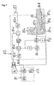
- Each transmitter uses a different pseudo-random sequence for the transmission time, so that always different stations superimpose, or at other times no superposition occurs. Random overlays are accepted, as illustrated in particular FIG. According to detail D X , the transmitters S2, S3 transmit simultaneously while sending time-delayed according to detail D Y.
- Such overlays may occur multiple times, but are acceptable because of the appropriate sampling rate in favor of the increased robustness of the transmitters as well as their compact design. All transmitters share the same frequency so full bandwidth is available for each transmitter as the available bandwidth per transmitter determines the accuracy. The combination "all transmitters use the same band” and “the transmitters are not synchronized” leads at the same time to the desired accuracy and robustness of the system.
- Each transmitter transmits at a transmission time only a short transmission burst B, which is detected by the receivers E 1 - E n .
- Stationary reference transmitters R1 to Rn or Rx 1 to Rx n in FIG. 3 serve as position references for error minimization and for calibrating the system.
- These transmit as well as the at least one mobile transmitter Sb, Sp of the mobile object from a Idenfrackingscode and signals that are detected to determine their maturity by the receiver.
- the reference signals are synchronized via a signal frequency SF2 of 250 MHz in the embodiment.
- the receivers according to FIG. 6 are likewise synchronized with one another via a signal frequency SF1 of 25 MHz in the exemplary embodiment according to FIG. 6.
- the receiver which are arranged in a receiver network RN according to FIG. 3, thus receive a first information via the clock line 13, a timestamp via the line 14 and their power supply via the line 15.
- the data acquired on the basis of this information is transmitted with the detected signals via the data line 17 to the data port DP of a central processing unit CPU, so that the position of the mobile object can be determined from the determined signals.
- the block Rx n next to Fig. 3 shows a matrix in which ⁇ tm a is the time difference relative to the last timestamp for each received transmitter ID and in which the information on the quality of the correlation for purposes of hard / soft decision in n Controller gives.
- the controller C calibrates the mutual transmission time of the receivers Rx and synchronizes the receiver network RN. With the aid of the controller C, the position of the relative mutual transmission time of Rx is calculated.
- At least four receivers are needed to locate an object in a three-dimensional space. Runtime differences are recorded at the respective receivers.
- the geometric solution of the position determination can be determined by the solution of a hyperbolic equation system.
- the reference signals are distributed via cables, preferably fiber optic cables.
- the mobile transmitter modules of the transmitters S, Sp, Sb emit time-limited transmit signals as transmit bursts B.
- the transmit bursts B are transmitted using non-synchronized pseudo-random patterns, which are a combination of the access mechanisms time division multiplexed and code division multiplexed, to thereby fully utilize the existing bandwidth as fully as possible.
- pseudo-random patterns are used, which are preferably prime sequences. The smaller primes are assigned to the faster moving stations, so in the embodiment of the transmitter Sb in the ball, while the higher primes are assigned to the slower moving stations Sp.
- the separation of two randomly simultaneously arriving signals is performed by the receiver, which tolerates unrecorded individual values. This is possible due to the high pulse rate.
- the analog received signals received at the RF front end are digitized in an evaluation unit and the reception times of the signals are determined by the respective transmitter at the reference time.
- the separation of the received signal into a plurality of signal sources (differentiation of the transmitters) and the characterization for each transmission signal of the current motion sequence software with a particular methodology is used, which has a plurality of algorithms with variable parameters. These are interactively adapted and combined depending on the situation.
- the transmitter and receiver have a hardware with which the trigger time for data recording can be detected exactly. Furthermore, an evaluation unit with a digital hardware for processing a synchronization signal is provided, which is fed via corresponding interfaces.
- the configuration phase Before the system goes into its normal operating mode, important data is gained in the configuration phase. This is necessary to calibrate the system, for example to take into account the runtime in the fiber optic network.
- a system check is performed to detect any problems in parts such as the receivers.
- synchronization takes place by means of the correlation function on the transmitters.
- the transmitters transmit time-equidistant data packets, so that an assignment is possible.
- the synchronization routine must therefore have "found" a data packet once for each transmitter and can then predict the next transmission time with a certain accuracy, since the transmission pattern is known. Accordingly, the trigger logic is driven to find the digitized data in memory again.
- the routine determines the distance data according to FIG. 2 from the expected transmission time t 0 under runtime calculation. This results in a search area s, within which the next signal must appear.
- Algebraic methods for solving the navigation equations have the disadvantage that, depending on the infrastructure, geometry and quality of the individual measurements at the receivers, they provide very variable and, in many cases, insufficient position accuracies. Therefore, algebraic algorithms are used only for initialization and monitoring of other algorithms. By using averaging methods, a significant improvement can be achieved depending on the frequency of position calculations. Furthermore, by taking into account quality information of the stochastically characteristic measurement, an additional optimization of the position accuracy can be achieved.
- the KALMAN filter is used, which combines the two indicated improvements and additionally allows the consideration of the current situation by means of suitable prediction models of the movement (situation awareness).
- methods for post-processing can be used, which are not subject to any time-limited computing time and can also be used outsourced.
- these provide additionally increased position accuracy, since larger areas can be used for curve smoothing. Even in these cases, it is ensured that the detected dynamic cases are taken into account appropriately.
- the data is processed as follows:
- the transmission timing sequence is synchronized. For this purpose, algorithms with reduced time resolution are used. The goal is simply to estimate the times of the future transmission times.
- the send bursts are continuously recorded with higher accuracy and the current position is calculated.
- the incoming signals are only evaluated in the estimated or previously calculated transmission or input time. In addition, the estimate of the next transmission time is tracked.
- data stored in zoom mode can be processed with additional algorithms.
- data may be processed in reverse temporal order, e.g. from both sides to a discontinuity (e.g., ball bouncing off goal posts).
- the receiver therefore acquires the data at high sampling frequency and stores it between.
- the relevant data is now further processed and, optionally, further stored in order to save it e.g. in zoom mode algorithms.
- Accuracy can be achieved by data post-processing and the integration of external sensors, e.g. Acceleration sensors in the ball or image data can be increased.
- the system provides e.g. every second the position data of all transmitters in operation.
- the 2.4 GHz band has been proposed as the transmission range, but in principle other bands can also be used in lower band ranges in order to to keep power consumption low. It is also conceivable, however, the use in the higher frequency range, for example 5.8 GHz, 9.4 GHz, 24 GHz at lower ranges and higher range resolution.
- the receivers detect the signals emitted by the transmitters and determine their transit time difference, they must be very precisely synchronized with one another, which can be achieved with a highly stable reference signal via the clock line 13 and in the exemplary embodiment fiber optic cable.
- the received data is supplied to the receivers E 1 -En via a data network to a central processing unit CPU, which calculates the position of the individual transmitters therefrom. These data consist of the transit time as well as the quality evaluation of the received signals.
- a return channel between mobile transmitters S, Sp, Sb and stationary receivers E 1 -E n is not required for the localization itself and would require an unnecessary increase in system complexity and hence cost.
- This concept has the advantage that the transmitters are only active for a short time, so that only low power consumption is incurred.
- the transmitters need not be synchronized, so that a transmitter-side receiver module can be omitted, making the transmitter much easier and more robust. Due to the pseudo-random sequences in the form of primes, the same transmitters are not always superimposed during a transmission period, so that the unfavorable situation that a far-flung transmitter constantly superimposes itself on a near-end transmitter can be avoided altogether. Thus, the "near-far" problem can be eliminated statistically. The collision probability of the transmission bursts B is reduced.
- the carrier frequency is approx. 2.4GHz. This results in a period of 0.4ns.
- a carrier phase evaluation would therefore have an ambiguity of 0.4ns.
- a carrier phase evaluation can therefore only be included to increase the accuracy if an accuracy of better than 0.4ns is achieved by other methods.
- ⁇ f describes the frequency offset when non-synchronized oscillators are used in the transmitters.
- ⁇ ⁇ is the phase offset between the oscillators.
- the transit time ⁇ can be determined via correlation e ⁇ (t) with the known transmission signal g (t).
- the accuracy of this correlation is a key parameter for positional accuracy.
- the accuracy of the correlation is determined by the properties of the autocorrelated signal, the methods used to calculate the correlation, and the perturbations.
- a transmission burst B lasts 25 ⁇ s, with 5 ⁇ s being scheduled as a guard period for switching the transmission output stage on and off.
- the transmitter ID sequence lasts 15 ⁇ s and includes 750 bits. The remaining 5 ⁇ s carry 250 bits of information as data. This results in a data rate of 50 megabits per second.
- a burst repetition rate of 0.5 ms is planned, while the player transmitters have a repetition rate of 4 ms. This results in a time utilization of 67.5%. This enables asynchronous, random-driven transmitter control.
- the result is a resulting minimum spatial resolution per broadcast burst for a ball of up to 20 mm and the player transmitter up to 44 mm.
- Fig. 7 shows a block diagram of the transmitter module.
- the module consists of a scheduler 80, a transmit data generator 81 and a transmit generator generator 82.
- the scheduler 80 controls the timings in the circuit. It receives the system clock from the broadcast generation 82 and in turn triggers both the transmission data generation 81 and the transmission generation 82.
- the transmission data is generated in the transmission data generation 81, sensor data also being able to be processed.
- the data is then modulated onto a radio frequency carrier in transmit burst generation 82. This is followed by the emission of the transmission burst via the antenna 83.
- the transmission data generation 81 consists of the data burst formation 81a, the transmitter ID block 81b, and the sensor data preparation 81c.
- the data burst shaping 81a processes the sensor data supplied from the sensor data processor 81c with the transmitter identifier from the transmitter ID block 81b, which is a bit sequence specific to each transmitter. The result is the data burst, which is forwarded to the transmission bus generation 82.
- the sensor data comes in the case of the ball transmitter from an acceleration sensor and may include the player transmitter, for example, medical data.
- the broadcast generation 82 includes the reference oscillator 82a, the high frequency generation, the modulator 82b and the output stage 82c.
- the transmission data is first filtered via data filter 82d to reduce the bandwidth in order to then modulate on the high-frequency carrier.
- the signal is amplified and then filtered in bandpass filter 82e to reject spurs.
- the broadcast burst is finally emitted.
- the scheduler 80 controls the timing generation of the data bursts and the turning on of the output stage 82c according to the time-division multiplexing method.
- the clock generator is correlated with the reference transmitter 84 receiving the synchronization clock 84b and comprising a fiber receiver 84c with filter and clock conditioning 84d, and an amplifier 84a with the transmitter Sp, Sb with quartz oscillator 85a, transistor and quartz 85b.
- the clock signal also affects modulator 82b via PIC 82j, PD & Divider 82k and loop filter 82i, which includes a low pass filter.
- Fig. 8 shows the functional blocks of a receiver.
- Radio frequency signals received via the antenna 90 are converted to an intermediate frequency and digitized there by means of an A / D converter.
- the digital processing unit 95 derives therefrom the time intervals of the received transmit signals of the individual transmitters with respect to the synchronization pulses which are distributed by the receiver block 94 containing an optical fiber receiver to all components in the receiver E.
- the so-called "raw runtime data" are still provided with a quality feature that includes the reception field strength or validity of the corresponding measured value before they are forwarded to the central computer.
- the received radio signals are amplified with a low-noise amplifier before being band-pass filtered. After repeated amplification and filtering, the mixture takes place in the intermediate frequency range.
- the digital processing unit includes a network card 95a for transmitting the data rate as runtime data 96.
- a frequency amplifier is disposed between the optical fiber receiver 94a and the RF portion 91.
- a sampling rate of about 200 MHz is used.
- the supplied samples are first stored in a memory having a ring buffer structure.
- the known transmission periods are searched for in the reception signal and then the correlation with the transmission pattern is carried out at predicted locations in the memory. This leads to a precise determination of the reception time. For ball and player If the arithmetic units necessary for the correlation are present several times in parallel. These are communicated from the central computer to be searched for transmission patterns. It is important to ensure that even in the most unfavorable constellation, all signals can still be evaluated. From the correlation units arises for the respective evaluated transmitter signals of the reception time with a quality mark - to evaluate the quality of the measured value - which is transmitted via the control PC and the data network infrastructure to the central computer CPU.
- All measured values of the receivers converge in the main computer CPU. They are sorted and grouped by means of the transmitter identification numbers, in order then to carry out the calculation of the position with the corresponding algorithms for each transmitter. The determined coordinates are then retrievable via a defined interface and can then be further evaluated.
- two reference signals are required, which are located centrally at a location on the system, e.g. be generated at the central computer CPU and distributed to all receivers and to the central computer.
- the frequencies of the two required frequency signals may e.g. in the range of 15-25 MHz and 150-250 MHz.
- the signals are carried out as square waves to obtain unique timestamps and fed via line 14 to the receivers.
- the reference transmitters R 1 - R n operate with trigger and clock signals supplied by the signal network.
- the receivers are preferably straight ahead receivers that operate at the synchronization frequencies.
- the receiver can also be designed as a single-superheterodyne receiver. In this case, an intermediate frequency is used, which then mixed in a second mixer stage to the output frequency and only has to be low-pass filtered.
- the advantage of this design is the completely free choice of the output frequency. For a given bandwidth of 80 MHz, this requires a theoretical sampling rate of 160 MHz. However, the bandwidth is effectively determined by the analog prefilter with a characteristic transfer function.
Landscapes
- Health & Medical Sciences (AREA)
- General Health & Medical Sciences (AREA)
- Physical Education & Sports Medicine (AREA)
- Radar, Positioning & Navigation (AREA)
- Engineering & Computer Science (AREA)
- General Physics & Mathematics (AREA)
- Physics & Mathematics (AREA)
- Remote Sensing (AREA)
- Position Fixing By Use Of Radio Waves (AREA)
- Mobile Radio Communication Systems (AREA)
- Measurement Of Velocity Or Position Using Acoustic Or Ultrasonic Waves (AREA)
- Radio Relay Systems (AREA)
- Radar Systems Or Details Thereof (AREA)
Claims (17)
- Procédé pour le suivi en temps réel continu de la position d'au moins un objet mobile dans un espace défini pluridimensionnel, comprenant au moins un émetteur (S, Sp, Sb) mobile, qui est placé sur au moins un objet mobile du système à analyser et dont les signaux sont reçus par des récepteurs (E1,...En) d'un réseau fixe récepteur et de traitement de signal et sont traités de façon centrale, les signaux émis par le au moins un émetteur étant des ondes électromagnétiques, envoyés dans une plage de bande de fréquence dans le procédé de multiplexage temporel et la bande de fréquence disponible étant utilisée comme un seul canal pour la maximisation de la précision de localisation,
caractérisé en ce que la communication entre l'émetteur (S, Sp, Sb) et les récepteurs (E1,...En) du réseau récepteur et de traitement de signal est basée sur le canal unique sans canal retour sur le principe du multiplexage temporel pseudo-aléatoire avec des modèles pseudo-aléatoires non synchronisés, dans lequel une séquence pseudo-aléatoire des moments d'émission du au moins un émetteur est utilisée, l'objet mobile émettant seulement et le réseau récepteur et de traitement de signal recevant seulement, et en ce que les signaux d'émission de différentes rafales d'émission (B) sont caractérisés avec une faible corrélation croisée, le modèle d'émission de l'émetteur étant déjà connu des récepteurs. - Procédé selon la revendication 1, caractérisé en ce que le principe du multiplexage temporel pseudo-aléatoire comprend l'émission (S, Sp, Sb) à des moments individuels irréguliers, chaque émetteur (S, Sp, Sb) utilisant une autre séquence pseudo-aléatoire pour le moment d'émission.
- Procédé selon la revendication 1 ou 2, caractérisé en ce que les émetteurs (E1,...En) évaluent avec la connaissance du multiplexage temporel pseudo-aléatoire et des modèles pseudo-aléatoires connus le moment de la prochaine rafale d'émission (B) d'un émetteur (S, Sp, Sb) défini.
- Procédé selon la revendication 3, caractérisé en ce qu'on analyse seulement les signaux qui apparaissent au moment défini auparavant de la prochaine rafale d'émission (B), le calcul préalable de la prochaine rafale d'émission de l'émetteur (S, Sp, Sb) défini étant de préférence asservi de façon continue.
- Procédé selon l'une quelconque des revendications précédentes, caractérisé en ce que les émetteurs sont miniaturisés de telle sorte qu'ils peuvent être utilisés également dans une balle.
- Procédé selon l'une quelconque des revendications précédentes, caractérisé en ce que la bande de fréquence se situe à environ 2,4 GHz et/ou à une largeur de bande de 80 MHz.
- Procédé selon l'une quelconque des revendications précédentes, caractérisé en ce que des émetteurs de référence (R1,...Rn) fixes sont utilisés comme références de position pour la minimisation des erreurs et pour l'étalonnage du système, qui émettent de la même façon que le au moins un émetteur mobile (S, Sp, Sb) du au moins un objet mobile à analyser un code d'identification dans une séquence et dont les signaux sont détectés pour déterminer leur heure d'arrivée sur les récepteurs respectifs par les récepteurs (R1,...Rn).
- Procédé selon l'une quelconque des revendications précédentes, caractérisé en ce que les émetteurs de référence sont synchronisés par câble, de préférence par câble en fibre de verre.
- Procédé selon l'une quelconque des revendications précédentes, caractérisé en ce que les rafales d'émission (B) sont envoyées avec l'utilisation de modèles pseudo-aléatoires non synchronisés, qui sont une combinaison des mécanismes d'accès multiplexage temporel et multiplexage de code, les modèles pseudo-aléatoires étant de préférence des séquences de nombres premiers.
- rocédé selon l'une quelconque des revendications précédentes, caractérisé en ce que, avec les rafales d'émission (B), la séparation d'au moins deux signaux, arrivant de façon aléatoire et simultanée, d'origine différente est effectuée par le récepteur.
- Procédé selon l'une quelconque des revendications précédentes, caractérisé en ce que les rafales d'émission (B) sont reliées avec un taux d'impulsion si élevé que des valeurs individuelles non enregistrées sont tolérées.
- Procédé selon l'une quelconque des revendications précédentes, caractérisé en ce que les signaux d'émission analogiques reçus sur le frontal HF sont numérisés dans une unité d'analyse et les moments de réception des signaux allant à l'émetteur respectif (S, Sp, Sb) sont définis et stockés.
- Procédé selon la revendication 12, caractérisé en ce que différents algorithmes peuvent être utilisés selon la situation pour le traitement des signaux reçus et stockés.
- Procédé selon l'une quelconque des revendications 12 ou 13, caractérisé en ce que, pour le traitement des signaux reçus, le signal est décomposé en tronçons qui se superposent éventuellement et un algorithme respectivement optimal ou plusieurs algorithmes sont utilisés en même temps pour les différents tronçons.
- Procédé selon l'une quelconque des revendications 12 à 14, caractérisé en ce que, pour le traitement de tronçons individuels des signaux reçus, on peut utiliser également un axe de temps non tourné, de sorte que par exemple des discontinuités sont approchées dans des processus très dynamiques par les deux côtés.
- Dispositif pour l'émission d'ondes électromagnétiques pour l'utilisation dans un procédé pour le suivi continu en temps réel de la position d'au moins un objet mobile dans un espace défini en pluridimensionnel comprenant- au moins un émetteur mobile, qui est placé sur au moins un objet mobile du système à analyser,- plusieurs émetteurs (E1, ...En) d'un réseau stationnaire récepteur et de traitement de signal pour la réception et pour le traitement des signaux envoyés par l'émetteur, qui sont des ondes émises dans une plage de bande de fréquence dans le procédé de multiplexage temporel,- un seul canal sur la bande de fréquence disponible,caractérisé en ce que des moyens de communication sont prévus, lesquels effectuent une transmission de l'émetteur (S, Sp, Sb) de l'objet mobile émettant seulement aux récepteurs (E1,...En) du réseau récepteur et de traitement de signal recevant seulement sur le principe du multiplexage temporel pseudo-aléatoire avec des modèles pseudo-aléatoires non synchronisés, sur lequel une séquence pseudo-aléatoire des moments d'émission du au moins un émetteur est utilisée, sur l'unique canal sans canal retour, et qu'il est prévu des moyens d'émission qui transmettent les signaux d'émission sous la forme de rafales d'émission différentes (B), avec faible corrélation croisée, le modèle d'émission de l'émetteur étant pré-connu des récepteurs.
- Dispositif selon la revendication 16, caractérisé en ce que les émetteurs de référence (R1,...Rn) avec des signaux de déclenchement et de synchronisation sont prévus, lesquels sont injectés par le réseau de signal.
Applications Claiming Priority (7)
| Application Number | Priority Date | Filing Date | Title |
|---|---|---|---|
| DE10250243 | 2002-10-28 | ||
| DE10250243 | 2002-10-28 | ||
| DE10250500 | 2002-10-29 | ||
| DE10250500 | 2002-10-29 | ||
| DE10252934A DE10252934A1 (de) | 2002-10-28 | 2002-11-14 | Verfahren zur kontinuierlichen Echtzeitverfolgung der Position von wenigstens einem mobilen Objekt sowie zugehörigen Sendern und Empfängern |
| DE10252934 | 2002-11-14 | ||
| PCT/EP2003/011893 WO2004038448A1 (fr) | 2002-10-28 | 2003-10-25 | Procede de localisation continue en temps reel d'au moins un objet mobile et emetteurs et recepteurs associes |
Publications (2)
| Publication Number | Publication Date |
|---|---|
| EP1556713A1 EP1556713A1 (fr) | 2005-07-27 |
| EP1556713B1 true EP1556713B1 (fr) | 2006-08-23 |
Family
ID=32180106
Family Applications (1)
| Application Number | Title | Priority Date | Filing Date |
|---|---|---|---|
| EP03772263A Expired - Lifetime EP1556713B1 (fr) | 2002-10-28 | 2003-10-25 | Procede de localisation continue en temps reel d'au moins un objet mobile et emetteurs et recepteurs associes |
Country Status (8)
| Country | Link |
|---|---|
| US (1) | US7139582B2 (fr) |
| EP (1) | EP1556713B1 (fr) |
| JP (1) | JP4405924B2 (fr) |
| AT (1) | ATE337562T1 (fr) |
| AU (1) | AU2003279324B8 (fr) |
| DE (1) | DE50304784D1 (fr) |
| ES (1) | ES2271659T3 (fr) |
| WO (1) | WO2004038448A1 (fr) |
Cited By (3)
| Publication number | Priority date | Publication date | Assignee | Title |
|---|---|---|---|---|
| DE102008032983A1 (de) | 2008-07-08 | 2010-02-25 | Fraunhofer-Gesellschaft zur Förderung der angewandten Forschung e.V. | Verfahren und Vorrichtung zum Bestimmen der sich ändernden Position eines mobilen Senders |
| DE102008052799A1 (de) | 2008-10-15 | 2010-05-06 | Fraunhofer-Gesellschaft zur Förderung der angewandten Forschung e.V. | System zum Bestimmen der Bewegung einer schwankenden Konstruktion |
| EP2405281A1 (fr) | 2010-07-09 | 2012-01-11 | Fraunhofer-Gesellschaft zur Förderung der angewandten Forschung | Procédé et dispositif de détermination de la position et de l'orientation d'un émetteur mobile |
Families Citing this family (54)
| Publication number | Priority date | Publication date | Assignee | Title |
|---|---|---|---|---|
| US6560461B1 (en) | 1997-08-04 | 2003-05-06 | Mundi Fomukong | Authorized location reporting paging system |
| US7095312B2 (en) * | 2004-05-19 | 2006-08-22 | Accurate Technologies, Inc. | System and method for tracking identity movement and location of sports objects |
| US7339526B2 (en) * | 2004-07-30 | 2008-03-04 | Novariant, Inc. | Synchronizing ranging signals in an asynchronous ranging or position system |
| US7532160B1 (en) * | 2004-07-30 | 2009-05-12 | Novariant, Inc. | Distributed radio frequency ranging signal receiver for navigation or position determination |
| US7339525B2 (en) * | 2004-07-30 | 2008-03-04 | Novariant, Inc. | Land-based local ranging signal methods and systems |
| US7342538B2 (en) * | 2004-07-30 | 2008-03-11 | Novariant, Inc. | Asynchronous local position determination system and method |
| US7315278B1 (en) * | 2004-07-30 | 2008-01-01 | Novariant, Inc. | Multiple frequency antenna structures and methods for receiving navigation or ranging signals |
| US7271766B2 (en) | 2004-07-30 | 2007-09-18 | Novariant, Inc. | Satellite and local system position determination |
| US7205939B2 (en) * | 2004-07-30 | 2007-04-17 | Novariant, Inc. | Land-based transmitter position determination |
| US7339524B2 (en) * | 2004-07-30 | 2008-03-04 | Novariant, Inc. | Analog decorrelation of ranging signals |
| EP1666916A3 (fr) * | 2004-12-03 | 2007-12-12 | William Forbes | Système de suivi |
| US10036249B2 (en) * | 2005-05-31 | 2018-07-31 | Caterpillar Inc. | Machine having boundary tracking system |
| US20080129824A1 (en) * | 2006-05-06 | 2008-06-05 | Ryan Scott Loveless | System and method for correlating objects in an event with a camera |
| US20070268366A1 (en) * | 2006-05-17 | 2007-11-22 | Ramesh Raskar | System and method for sensing geometric and photometric attributes of a scene with multiplexed illumination and solid state optical devices |
| DE102007001820B3 (de) * | 2006-10-12 | 2008-01-24 | Cairos Technologies Ag | Konzept zur Erkennung eines Kontakts mit einem Spielgerät |
| DE102007002672B4 (de) * | 2007-01-18 | 2023-08-10 | Airbus Defence and Space GmbH | Verfahren zur Ermittlung eines Flugzeugzustandes |
| DE102007015493A1 (de) * | 2007-03-30 | 2008-10-02 | Cairos Technologies Ag | Bewegungsbereich für einen mobilen Gegenstand und Auswertungsvorrichtung zum Feststellen einer Position eines mobilen Gegenstands |
| WO2009022265A2 (fr) * | 2007-08-10 | 2009-02-19 | Philips Intellectual Property & Standards Gmbh | Système de localisation d'objets en mouvement |
| CN101978374A (zh) | 2008-03-03 | 2011-02-16 | 耐克国际有限公司 | 交互式运动设备系统 |
| US20090298588A1 (en) * | 2008-05-31 | 2009-12-03 | Venkatesh P. Gopinath | Method of automatically detecting offside in Soccer using fixed and wireless sensors and central server |
| DE102008057705A1 (de) | 2008-11-17 | 2010-05-20 | Cairos Technologies Ag | Erfassen und Bereitstellen von Spielerinformationen mit spielerseitigem Sensor |
| US8231506B2 (en) | 2008-12-05 | 2012-07-31 | Nike, Inc. | Athletic performance monitoring systems and methods in a team sports environment |
| US8172722B2 (en) * | 2008-12-05 | 2012-05-08 | Nike, Inc. | Athletic performance monitoring systems and methods in a team sports environment |
| US8628453B2 (en) | 2008-12-05 | 2014-01-14 | Nike, Inc. | Athletic performance monitoring systems and methods in a team sports environment |
| US20110039623A1 (en) * | 2009-08-12 | 2011-02-17 | 3 Legged Dog, Inc. | Interactive system and method for digital artifact relocation and activation |
| US20110039622A1 (en) * | 2009-08-12 | 2011-02-17 | 3 Legged Dog, Inc. | Interactive system and method for digital artifact relocation and activation |
| US9357921B2 (en) | 2009-10-16 | 2016-06-07 | At&T Intellectual Property I, Lp | Wearable health monitoring system |
| US8786415B2 (en) * | 2010-02-24 | 2014-07-22 | Sportvision, Inc. | Tracking system using proximity and/or presence |
| CA2955632A1 (fr) | 2010-11-10 | 2012-05-18 | Nike Innovate C.V. | Systemes et procedes permettant de mesurer et d'afficher une activite sportive en fonction du temps |
| JP5187389B2 (ja) * | 2010-12-28 | 2013-04-24 | ブラザー工業株式会社 | 通信装置、通信方法、および通信プログラム |
| KR101767794B1 (ko) | 2011-02-17 | 2017-08-11 | 나이키 이노베이트 씨.브이. | 위치 맵핑 |
| EP2518680A1 (fr) * | 2011-04-28 | 2012-10-31 | RapidBlue Solutions Oy | Profilage de consommateur basé sur la localisation |
| US9852333B2 (en) * | 2011-09-20 | 2017-12-26 | Fraunhofer—Gesellschaft zur Förderung der angewandten Forschung e.V. | System and method for detecting a user-dependent state of a sport object |
| US10118078B2 (en) | 2011-11-02 | 2018-11-06 | Toca Football, Inc. | System, apparatus and method for ball throwing machine and intelligent goal |
| US8874139B2 (en) * | 2012-10-25 | 2014-10-28 | Sstatzz Oy | Position location system and method |
| DE102013105936B4 (de) | 2013-06-07 | 2025-04-03 | Fraunhofer-Gesellschaft zur Förderung der angewandten Forschung e.V. | Konzept zum Senden und/oder zum Empfangen von Datenpaketen für ein System zum Detektieren eines Ereignisses, entsprechend einer Überquerung eines Objekts über eine überwachte Linie |
| WO2015084870A1 (fr) * | 2013-12-02 | 2015-06-11 | Unlicensed Chimp Technologies, Llc | Système de positionnement local et de réponse |
| US9313619B2 (en) | 2014-04-24 | 2016-04-12 | At&T Mobility Ii Llc | Facilitating estimation of mobile device presence inside a defined region |
| CN103995250B (zh) * | 2014-05-29 | 2016-08-24 | 南京泰系信息技术有限公司 | 射频标签轨迹追踪方法 |
| CN105105755B (zh) * | 2015-06-25 | 2017-10-31 | 简极科技有限公司 | 一种智能球场系统及其数据获取方法 |
| DE102016120250A1 (de) | 2016-10-24 | 2018-04-26 | Fraunhofer-Gesellschaft zur Förderung der angewandten Forschung e.V. | Verfahren und vorrichtung zum bestimmen einer position eines beweglichen objekts sowie system umfassend die vorrichtung |
| KR101841426B1 (ko) * | 2017-02-20 | 2018-03-23 | (주)에어패스 | 루틴훈련장치 및 루틴훈련방법 |
| EP3581956B1 (fr) * | 2018-06-14 | 2025-01-15 | Swiss Timing Ltd. | Procédé pour calculer la position d'un athlète sur un terrain de sport |
| CA3128038A1 (fr) | 2019-01-31 | 2020-08-06 | Rypplzz, Inc. | Systemes et procedes pour la realite augmentee avec un suivi precis |
| US12474813B2 (en) | 2019-01-31 | 2025-11-18 | Rypplzz, Inc. | Systems and methods for augmented reality with precise tracking |
| US20200330830A1 (en) * | 2019-04-17 | 2020-10-22 | PFC Shared Services, LLC | Golf Ball Tracking System |
| FR3098310B1 (fr) * | 2019-07-05 | 2022-01-21 | Groupe Paris Turf | Système de suivi d’une pluralité de concurrents lors d’une course, procédé de suivi et procédé de détermination associés |
| GB201910548D0 (en) * | 2019-07-23 | 2019-09-04 | Sullivan Patrick John | Positional Detection System |
| US11207582B2 (en) | 2019-11-15 | 2021-12-28 | Toca Football, Inc. | System and method for a user adaptive training and gaming platform |
| US11710316B2 (en) | 2020-08-13 | 2023-07-25 | Toca Football, Inc. | System and method for object tracking and metric generation |
| US11514590B2 (en) | 2020-08-13 | 2022-11-29 | Toca Football, Inc. | System and method for object tracking |
| CN112162256B (zh) * | 2020-09-29 | 2023-08-01 | 中国船舶集团有限公司第七二四研究所 | 一种基于脉冲相关的级联式多维度径向运动特征检测方法 |
| US12343612B2 (en) * | 2021-07-08 | 2025-07-01 | Sportsmedia Technology Corporation | Automated offside detection and visualization for sports |
| WO2024209296A1 (fr) * | 2023-04-05 | 2024-10-10 | Mobileye Vision Technologies Ltd. | Appareil radar, système et procédé |
Family Cites Families (19)
| Publication number | Priority date | Publication date | Assignee | Title |
|---|---|---|---|---|
| US3782730A (en) * | 1971-12-02 | 1974-01-01 | Euronics Ltd | Golf ball |
| US4660039A (en) | 1985-02-14 | 1987-04-21 | Barricks Mary S | System for locating a sport object |
| DE3901720A1 (de) * | 1989-01-21 | 1990-07-26 | Hoechst Ag | Substituierte benzo(b)pyrane, verfahren zu ihrer herstellung, ihre verwendung sowie pharmazeutische praeparate auf basis dieser verbindungen |
| US5150310A (en) * | 1989-08-30 | 1992-09-22 | Consolve, Inc. | Method and apparatus for position detection |
| SE9003913D0 (sv) | 1990-12-07 | 1990-12-07 | Ericsson Telefon Ab L M | A method of locating a mobile station in a cellular mobile radio system |
| US5477459A (en) * | 1992-03-06 | 1995-12-19 | Clegg; Philip M. | Real time three-dimensional machine locating system |
| US5600706A (en) * | 1992-04-08 | 1997-02-04 | U S West, Inc. | Method and system for determining the position of a mobile receiver |
| US5583517A (en) * | 1992-08-20 | 1996-12-10 | Nexus 1994 Limited | Multi-path resistant frequency-hopped spread spectrum mobile location system |
| US5513854A (en) | 1993-04-19 | 1996-05-07 | Daver; Gil J. G. | System used for real time acquistion of data pertaining to persons in motion |
| US5327144A (en) | 1993-05-07 | 1994-07-05 | Associated Rt, Inc. | Cellular telephone location system |
| US5485163A (en) * | 1994-03-30 | 1996-01-16 | Motorola, Inc. | Personal locator system |
| US5589517A (en) * | 1994-04-08 | 1996-12-31 | Mitsubishi Chemical Corporation | Modified ion exchange resins and use thereof |
| US6041046A (en) * | 1995-07-14 | 2000-03-21 | Omnipoint Corporation | Cyclic time hopping in time division multiple access communication system |
| GB9603017D0 (en) | 1996-02-14 | 1996-04-10 | Raychem Sa Nv | Optical fibre distribution system |
| US6204813B1 (en) * | 1998-02-20 | 2001-03-20 | Trakus, Inc. | Local area multiple object tracking system |
| US5926133A (en) * | 1997-07-21 | 1999-07-20 | Denso Corporation | Differentially corrected position location system and method for mobile communication networks |
| US5912644A (en) * | 1997-08-05 | 1999-06-15 | Wang; James J. M. | Spread spectrum position determination, ranging and communication system |
| US6522296B2 (en) * | 2001-06-25 | 2003-02-18 | Harris Corporation | Method and system for calibrating wireless location systems |
| AU2003220185B2 (en) * | 2002-03-12 | 2007-05-10 | Menache, Llc | Motion tracking system and method |
-
2003
- 2003-10-25 JP JP2004545999A patent/JP4405924B2/ja not_active Expired - Fee Related
- 2003-10-25 AT AT03772263T patent/ATE337562T1/de active
- 2003-10-25 AU AU2003279324A patent/AU2003279324B8/en not_active Ceased
- 2003-10-25 WO PCT/EP2003/011893 patent/WO2004038448A1/fr not_active Ceased
- 2003-10-25 EP EP03772263A patent/EP1556713B1/fr not_active Expired - Lifetime
- 2003-10-25 DE DE50304784T patent/DE50304784D1/de not_active Expired - Lifetime
- 2003-10-25 ES ES03772263T patent/ES2271659T3/es not_active Expired - Lifetime
- 2003-10-27 US US10/693,631 patent/US7139582B2/en not_active Expired - Lifetime
Cited By (7)
| Publication number | Priority date | Publication date | Assignee | Title |
|---|---|---|---|---|
| DE102008032983A1 (de) | 2008-07-08 | 2010-02-25 | Fraunhofer-Gesellschaft zur Förderung der angewandten Forschung e.V. | Verfahren und Vorrichtung zum Bestimmen der sich ändernden Position eines mobilen Senders |
| DE102008052799A1 (de) | 2008-10-15 | 2010-05-06 | Fraunhofer-Gesellschaft zur Förderung der angewandten Forschung e.V. | System zum Bestimmen der Bewegung einer schwankenden Konstruktion |
| CN102187248A (zh) * | 2008-10-15 | 2011-09-14 | 弗兰霍菲尔运输应用研究公司 | 用于确定摇摆结构运动的系统 |
| DE102008052799B4 (de) * | 2008-10-15 | 2011-10-20 | Fraunhofer-Gesellschaft zur Förderung der angewandten Forschung e.V. | Anordnung zum Kalibrieren eines Funksystems |
| CN102187248B (zh) * | 2008-10-15 | 2013-11-27 | 弗兰霍菲尔运输应用研究公司 | 用于确定摇摆结构运动的系统 |
| EP2405281A1 (fr) | 2010-07-09 | 2012-01-11 | Fraunhofer-Gesellschaft zur Förderung der angewandten Forschung | Procédé et dispositif de détermination de la position et de l'orientation d'un émetteur mobile |
| WO2012004010A2 (fr) | 2010-07-09 | 2012-01-12 | Fraunhofer-Gesellschaft zur Förderung der angewandten Forschung e.V. | Procédé et dispositif de détermination de la position et de l'orientation d'un émetteur mobile |
Also Published As
| Publication number | Publication date |
|---|---|
| US7139582B2 (en) | 2006-11-21 |
| AU2003279324B8 (en) | 2009-06-04 |
| AU2003279324C1 (en) | 2009-05-28 |
| US20040171388A1 (en) | 2004-09-02 |
| JP2006504088A (ja) | 2006-02-02 |
| EP1556713A1 (fr) | 2005-07-27 |
| JP4405924B2 (ja) | 2010-01-27 |
| ES2271659T3 (es) | 2007-04-16 |
| AU2003279324A1 (en) | 2004-05-13 |
| WO2004038448A1 (fr) | 2004-05-06 |
| AU2003279324B2 (en) | 2008-10-23 |
| DE50304784D1 (de) | 2006-10-05 |
| ATE337562T1 (de) | 2006-09-15 |
Similar Documents
| Publication | Publication Date | Title |
|---|---|---|
| EP1556713B1 (fr) | Procede de localisation continue en temps reel d'au moins un objet mobile et emetteurs et recepteurs associes | |
| DE10055289B4 (de) | System zur Bestimmung der Position eines Objekts | |
| DE60219399T2 (de) | System zur Ortung eines Senders | |
| DE10252934A1 (de) | Verfahren zur kontinuierlichen Echtzeitverfolgung der Position von wenigstens einem mobilen Objekt sowie zugehörigen Sendern und Empfängern | |
| DE60222606T2 (de) | Verfahren und Vorrichtung zur Positionsbestimmung mit hoher Genauigkeit unter Verwendung von Suchmodus-Entfernungstechniken | |
| DE69913118T2 (de) | Verfolgungssystem im sport | |
| DE10246922B4 (de) | Übertragungseinrichtungslokalisierung für ein Ultrabreitband -CDMA- Kommunikationssystem mit übertragenem Bezugssignal | |
| DE602004002310T2 (de) | Ortungssystem | |
| DE60027654T2 (de) | Verfahren und Gerät zur Positionserkennung | |
| DE69027872T2 (de) | System zum Folgen eines Flugzeuges über einer Fläche. | |
| DE112015002659T5 (de) | Verfahren, Vorrichtung und Computerprogrammprodukt zur Echtzeit-Ortungssystem-Referenzierung in Umgebungen mit physischer und Funkfrequenzbelastung | |
| WO2010003699A1 (fr) | Procédé et dispositif de détermination de la position changeante d'un émetteur mobile | |
| GB2383708A (en) | Position determination | |
| DE10053959A1 (de) | Positionsbestimmungsverfahren und -vorrichtung | |
| DE102014004981B4 (de) | Verfahren zur Bestimmung der relativen Position wenigstens einer passiven Ortungseinrichtung durch wenigstens eine aktive Ortungseinrichtung | |
| EP2465310B1 (fr) | Procédé et agencement pour la mesure de la durée de propagation d'un signal entre deux stations de l'agencement | |
| DE102021107220B4 (de) | System und Verfahren zum Detektieren und Lokalisieren einer Signalquelle | |
| EP0740801B1 (fr) | Dispositif de mesure de position et procede permettant de determiner le temps de propagation d'un rayonnement energetique emis entre un poste de base et un objet mobile | |
| EP1666912A1 (fr) | Procédé et système pour determiner la position d'un objet | |
| DE20114245U1 (de) | Mobile Navigationsvorrichtung für ein zellulares Funknetz | |
| DE4042329B3 (de) | Radarsystem | |
| DE10324651A1 (de) | Verfahren und System zur Identifikation und Ortsbestimmung von Objekten | |
| EP3159710B1 (fr) | Procédé de détermination de position d'une unité mobile | |
| Vydhyanathan et al. | Augmenting low-cost GPS/INS with ultra-wideband transceivers for multi-platform relative navigation | |
| DE102017118324A1 (de) | Anordnung und Verfahren zur Abstandsmessung zwischen Geräten in einem Funksystem |
Legal Events
| Date | Code | Title | Description |
|---|---|---|---|
| PUAI | Public reference made under article 153(3) epc to a published international application that has entered the european phase |
Free format text: ORIGINAL CODE: 0009012 |
|
| 17P | Request for examination filed |
Effective date: 20050524 |
|
| AK | Designated contracting states |
Kind code of ref document: A1 Designated state(s): AT BE BG CH CY CZ DE DK EE ES FI FR GB GR HU IE IT LI LU MC NL PT RO SE SI SK TR |
|
| AX | Request for extension of the european patent |
Extension state: AL LT LV MK |
|
| RIN1 | Information on inventor provided before grant (corrected) |
Inventor name: BREILING, MARCO Inventor name: KOEHLER, STEFAN Inventor name: HOFMANN, GUENTER Inventor name: BLIESZE, MARCUS Inventor name: EBERLEIN, ERNST Inventor name: COURONNE, SYLVIA Inventor name: VON DER GRUEN, THOMAS Inventor name: RETKOWSKI, REINER |
|
| RAX | Requested extension states of the european patent have changed |
Extension state: MK Payment date: 20050523 |
|
| GRAP | Despatch of communication of intention to grant a patent |
Free format text: ORIGINAL CODE: EPIDOSNIGR1 |
|
| GRAS | Grant fee paid |
Free format text: ORIGINAL CODE: EPIDOSNIGR3 |
|
| GRAA | (expected) grant |
Free format text: ORIGINAL CODE: 0009210 |
|
| AK | Designated contracting states |
Kind code of ref document: B1 Designated state(s): AT BE BG CH CY CZ DE DK EE ES FI FR GB GR HU IE IT LI LU MC NL PT RO SE SI SK TR |
|
| AX | Request for extension of the european patent |
Extension state: MK |
|
| PG25 | Lapsed in a contracting state [announced via postgrant information from national office to epo] |
Ref country code: SI Free format text: LAPSE BECAUSE OF FAILURE TO SUBMIT A TRANSLATION OF THE DESCRIPTION OR TO PAY THE FEE WITHIN THE PRESCRIBED TIME-LIMIT Effective date: 20060823 Ref country code: RO Free format text: LAPSE BECAUSE OF FAILURE TO SUBMIT A TRANSLATION OF THE DESCRIPTION OR TO PAY THE FEE WITHIN THE PRESCRIBED TIME-LIMIT Effective date: 20060823 Ref country code: IE Free format text: LAPSE BECAUSE OF FAILURE TO SUBMIT A TRANSLATION OF THE DESCRIPTION OR TO PAY THE FEE WITHIN THE PRESCRIBED TIME-LIMIT Effective date: 20060823 Ref country code: CZ Free format text: LAPSE BECAUSE OF FAILURE TO SUBMIT A TRANSLATION OF THE DESCRIPTION OR TO PAY THE FEE WITHIN THE PRESCRIBED TIME-LIMIT Effective date: 20060823 Ref country code: IT Free format text: LAPSE BECAUSE OF FAILURE TO SUBMIT A TRANSLATION OF THE DESCRIPTION OR TO PAY THE FEE WITHIN THE PRESCRIBED TIME-LIMIT;WARNING: LAPSES OF ITALIAN PATENTS WITH EFFECTIVE DATE BEFORE 2007 MAY HAVE OCCURRED AT ANY TIME BEFORE 2007. THE CORRECT EFFECTIVE DATE MAY BE DIFFERENT FROM THE ONE RECORDED. Effective date: 20060823 Ref country code: SK Free format text: LAPSE BECAUSE OF FAILURE TO SUBMIT A TRANSLATION OF THE DESCRIPTION OR TO PAY THE FEE WITHIN THE PRESCRIBED TIME-LIMIT Effective date: 20060823 |
|
| REG | Reference to a national code |
Ref country code: GB Ref legal event code: FG4D Free format text: NOT ENGLISH |
|
| REG | Reference to a national code |
Ref country code: CH Ref legal event code: EP |
|
| REG | Reference to a national code |
Ref country code: IE Ref legal event code: FG4D Free format text: LANGUAGE OF EP DOCUMENT: GERMAN |
|
| REF | Corresponds to: |
Ref document number: 50304784 Country of ref document: DE Date of ref document: 20061005 Kind code of ref document: P |
|
| PG25 | Lapsed in a contracting state [announced via postgrant information from national office to epo] |
Ref country code: MC Free format text: LAPSE BECAUSE OF NON-PAYMENT OF DUE FEES Effective date: 20061031 |
|
| PG25 | Lapsed in a contracting state [announced via postgrant information from national office to epo] |
Ref country code: DK Free format text: LAPSE BECAUSE OF FAILURE TO SUBMIT A TRANSLATION OF THE DESCRIPTION OR TO PAY THE FEE WITHIN THE PRESCRIBED TIME-LIMIT Effective date: 20061123 Ref country code: SE Free format text: LAPSE BECAUSE OF FAILURE TO SUBMIT A TRANSLATION OF THE DESCRIPTION OR TO PAY THE FEE WITHIN THE PRESCRIBED TIME-LIMIT Effective date: 20061123 Ref country code: BG Free format text: LAPSE BECAUSE OF FAILURE TO SUBMIT A TRANSLATION OF THE DESCRIPTION OR TO PAY THE FEE WITHIN THE PRESCRIBED TIME-LIMIT Effective date: 20061123 |
|
| REG | Reference to a national code |
Ref country code: CH Ref legal event code: NV Representative=s name: LUCHS & PARTNER PATENTANWAELTE |
|
| RAP2 | Party data changed (patent owner data changed or rights of a patent transferred) |
Owner name: FRAUNHOFER-GESELLSCHAFT ZUR FOERDERUNG DER ANGEWAN |
|
| PG25 | Lapsed in a contracting state [announced via postgrant information from national office to epo] |
Ref country code: PT Free format text: LAPSE BECAUSE OF FAILURE TO SUBMIT A TRANSLATION OF THE DESCRIPTION OR TO PAY THE FEE WITHIN THE PRESCRIBED TIME-LIMIT Effective date: 20070125 |
|
| NLT2 | Nl: modifications (of names), taken from the european patent patent bulletin |
Owner name: FRAUNHOFER-GESELLSCHAFT ZUR Effective date: 20070117 |
|
| REG | Reference to a national code |
Ref country code: IE Ref legal event code: FD4D |
|
| ET | Fr: translation filed | ||
| REG | Reference to a national code |
Ref country code: ES Ref legal event code: FG2A Ref document number: 2271659 Country of ref document: ES Kind code of ref document: T3 |
|
| PLBE | No opposition filed within time limit |
Free format text: ORIGINAL CODE: 0009261 |
|
| STAA | Information on the status of an ep patent application or granted ep patent |
Free format text: STATUS: NO OPPOSITION FILED WITHIN TIME LIMIT |
|
| 26N | No opposition filed |
Effective date: 20070524 |
|
| PG25 | Lapsed in a contracting state [announced via postgrant information from national office to epo] |
Ref country code: GR Free format text: LAPSE BECAUSE OF FAILURE TO SUBMIT A TRANSLATION OF THE DESCRIPTION OR TO PAY THE FEE WITHIN THE PRESCRIBED TIME-LIMIT Effective date: 20061124 |
|
| PG25 | Lapsed in a contracting state [announced via postgrant information from national office to epo] |
Ref country code: EE Free format text: LAPSE BECAUSE OF FAILURE TO SUBMIT A TRANSLATION OF THE DESCRIPTION OR TO PAY THE FEE WITHIN THE PRESCRIBED TIME-LIMIT Effective date: 20060823 |
|
| PG25 | Lapsed in a contracting state [announced via postgrant information from national office to epo] |
Ref country code: TR Free format text: LAPSE BECAUSE OF FAILURE TO SUBMIT A TRANSLATION OF THE DESCRIPTION OR TO PAY THE FEE WITHIN THE PRESCRIBED TIME-LIMIT Effective date: 20060823 Ref country code: LU Free format text: LAPSE BECAUSE OF NON-PAYMENT OF DUE FEES Effective date: 20061025 Ref country code: HU Free format text: LAPSE BECAUSE OF FAILURE TO SUBMIT A TRANSLATION OF THE DESCRIPTION OR TO PAY THE FEE WITHIN THE PRESCRIBED TIME-LIMIT Effective date: 20070224 |
|
| PG25 | Lapsed in a contracting state [announced via postgrant information from national office to epo] |
Ref country code: CY Free format text: LAPSE BECAUSE OF FAILURE TO SUBMIT A TRANSLATION OF THE DESCRIPTION OR TO PAY THE FEE WITHIN THE PRESCRIBED TIME-LIMIT Effective date: 20060823 |
|
| REG | Reference to a national code |
Ref country code: FR Ref legal event code: PLFP Year of fee payment: 13 |
|
| REG | Reference to a national code |
Ref country code: FR Ref legal event code: PLFP Year of fee payment: 14 |
|
| REG | Reference to a national code |
Ref country code: FR Ref legal event code: PLFP Year of fee payment: 15 |
|
| REG | Reference to a national code |
Ref country code: FR Ref legal event code: PLFP Year of fee payment: 16 |
|
| PGFP | Annual fee paid to national office [announced via postgrant information from national office to epo] |
Ref country code: NL Payment date: 20201020 Year of fee payment: 18 |
|
| PGFP | Annual fee paid to national office [announced via postgrant information from national office to epo] |
Ref country code: FR Payment date: 20201020 Year of fee payment: 18 Ref country code: CH Payment date: 20201022 Year of fee payment: 18 Ref country code: DE Payment date: 20201022 Year of fee payment: 18 Ref country code: AT Payment date: 20201016 Year of fee payment: 18 Ref country code: GB Payment date: 20201022 Year of fee payment: 18 Ref country code: ES Payment date: 20201117 Year of fee payment: 18 Ref country code: IT Payment date: 20201030 Year of fee payment: 18 Ref country code: FI Payment date: 20201019 Year of fee payment: 18 |
|
| PGFP | Annual fee paid to national office [announced via postgrant information from national office to epo] |
Ref country code: BE Payment date: 20201020 Year of fee payment: 18 |
|
| REG | Reference to a national code |
Ref country code: DE Ref legal event code: R119 Ref document number: 50304784 Country of ref document: DE |
|
| REG | Reference to a national code |
Ref country code: FI Ref legal event code: MAE |
|
| REG | Reference to a national code |
Ref country code: CH Ref legal event code: PL |
|
| REG | Reference to a national code |
Ref country code: NL Ref legal event code: MM Effective date: 20211101 |
|
| REG | Reference to a national code |
Ref country code: AT Ref legal event code: MM01 Ref document number: 337562 Country of ref document: AT Kind code of ref document: T Effective date: 20211025 |
|
| REG | Reference to a national code |
Ref country code: BE Ref legal event code: MM Effective date: 20211031 |
|
| GBPC | Gb: european patent ceased through non-payment of renewal fee |
Effective date: 20211025 |
|
| PG25 | Lapsed in a contracting state [announced via postgrant information from national office to epo] |
Ref country code: NL Free format text: LAPSE BECAUSE OF NON-PAYMENT OF DUE FEES Effective date: 20211101 Ref country code: GB Free format text: LAPSE BECAUSE OF NON-PAYMENT OF DUE FEES Effective date: 20211025 Ref country code: DE Free format text: LAPSE BECAUSE OF NON-PAYMENT OF DUE FEES Effective date: 20220503 Ref country code: BE Free format text: LAPSE BECAUSE OF NON-PAYMENT OF DUE FEES Effective date: 20211031 |
|
| PG25 | Lapsed in a contracting state [announced via postgrant information from national office to epo] |
Ref country code: LI Free format text: LAPSE BECAUSE OF NON-PAYMENT OF DUE FEES Effective date: 20211031 Ref country code: FI Free format text: LAPSE BECAUSE OF NON-PAYMENT OF DUE FEES Effective date: 20211025 Ref country code: CH Free format text: LAPSE BECAUSE OF NON-PAYMENT OF DUE FEES Effective date: 20211031 Ref country code: AT Free format text: LAPSE BECAUSE OF NON-PAYMENT OF DUE FEES Effective date: 20211025 |
|
| PG25 | Lapsed in a contracting state [announced via postgrant information from national office to epo] |
Ref country code: FR Free format text: LAPSE BECAUSE OF NON-PAYMENT OF DUE FEES Effective date: 20211031 |
|
| PG25 | Lapsed in a contracting state [announced via postgrant information from national office to epo] |
Ref country code: IT Free format text: LAPSE BECAUSE OF NON-PAYMENT OF DUE FEES Effective date: 20211025 |
|
| REG | Reference to a national code |
Ref country code: ES Ref legal event code: FD2A Effective date: 20230203 |
|
| PG25 | Lapsed in a contracting state [announced via postgrant information from national office to epo] |
Ref country code: ES Free format text: LAPSE BECAUSE OF NON-PAYMENT OF DUE FEES Effective date: 20211026 |