EP1556724B1 - Cable de telecommunication comprenant un coeur optique raccorde et procede permettant de raccorder ledit coeur - Google Patents
Cable de telecommunication comprenant un coeur optique raccorde et procede permettant de raccorder ledit coeur Download PDFInfo
- Publication number
- EP1556724B1 EP1556724B1 EP02791656A EP02791656A EP1556724B1 EP 1556724 B1 EP1556724 B1 EP 1556724B1 EP 02791656 A EP02791656 A EP 02791656A EP 02791656 A EP02791656 A EP 02791656A EP 1556724 B1 EP1556724 B1 EP 1556724B1
- Authority
- EP
- European Patent Office
- Prior art keywords
- optical
- optical core
- optical fibers
- section
- strength member
- Prior art date
- Legal status (The legal status is an assumption and is not a legal conclusion. Google has not performed a legal analysis and makes no representation as to the accuracy of the status listed.)
- Expired - Lifetime
Links
- 230000003287 optical effect Effects 0.000 title claims abstract description 99
- 238000000034 method Methods 0.000 title claims abstract description 25
- 239000013307 optical fiber Substances 0.000 claims abstract description 52
- 239000000463 material Substances 0.000 claims abstract description 33
- 239000012815 thermoplastic material Substances 0.000 claims abstract description 10
- 238000000576 coating method Methods 0.000 claims description 31
- 239000011248 coating agent Substances 0.000 claims description 28
- 239000008199 coating composition Substances 0.000 claims description 18
- 239000007788 liquid Substances 0.000 claims description 8
- 230000005855 radiation Effects 0.000 claims description 7
- 229920001169 thermoplastic Polymers 0.000 claims description 7
- 239000004416 thermosoftening plastic Substances 0.000 claims description 6
- 239000011241 protective layer Substances 0.000 claims description 4
- 238000004519 manufacturing process Methods 0.000 abstract description 16
- 230000003014 reinforcing effect Effects 0.000 description 24
- 239000010410 layer Substances 0.000 description 17
- 239000000835 fiber Substances 0.000 description 11
- 239000000203 mixture Substances 0.000 description 8
- 229910000831 Steel Inorganic materials 0.000 description 5
- 239000010959 steel Substances 0.000 description 5
- 238000009825 accumulation Methods 0.000 description 4
- NIXOWILDQLNWCW-UHFFFAOYSA-N acrylic acid group Chemical group C(C=C)(=O)O NIXOWILDQLNWCW-UHFFFAOYSA-N 0.000 description 4
- 239000003085 diluting agent Substances 0.000 description 4
- 239000000178 monomer Substances 0.000 description 4
- -1 polyethylene Polymers 0.000 description 4
- 239000013047 polymeric layer Substances 0.000 description 4
- 239000011344 liquid material Substances 0.000 description 3
- 229920000642 polymer Polymers 0.000 description 3
- 239000002861 polymer material Substances 0.000 description 3
- 239000004698 Polyethylene Substances 0.000 description 2
- 239000004743 Polypropylene Substances 0.000 description 2
- 230000001133 acceleration Effects 0.000 description 2
- 239000000654 additive Substances 0.000 description 2
- 238000007796 conventional method Methods 0.000 description 2
- 238000005520 cutting process Methods 0.000 description 2
- 238000006073 displacement reaction Methods 0.000 description 2
- 230000000694 effects Effects 0.000 description 2
- 238000009472 formulation Methods 0.000 description 2
- 238000003780 insertion Methods 0.000 description 2
- 230000037431 insertion Effects 0.000 description 2
- 239000002184 metal Substances 0.000 description 2
- 229910052751 metal Inorganic materials 0.000 description 2
- 239000007769 metal material Substances 0.000 description 2
- 229920000573 polyethylene Polymers 0.000 description 2
- 229920001155 polypropylene Polymers 0.000 description 2
- KCTAWXVAICEBSD-UHFFFAOYSA-N prop-2-enoyloxy prop-2-eneperoxoate Chemical compound C=CC(=O)OOOC(=O)C=C KCTAWXVAICEBSD-UHFFFAOYSA-N 0.000 description 2
- 230000001681 protective effect Effects 0.000 description 2
- 229910001220 stainless steel Inorganic materials 0.000 description 2
- 239000010935 stainless steel Substances 0.000 description 2
- PSGCQDPCAWOCSH-UHFFFAOYSA-N (4,7,7-trimethyl-3-bicyclo[2.2.1]heptanyl) prop-2-enoate Chemical compound C1CC2(C)C(OC(=O)C=C)CC1C2(C)C PSGCQDPCAWOCSH-UHFFFAOYSA-N 0.000 description 1
- NIXOWILDQLNWCW-UHFFFAOYSA-M Acrylate Chemical compound [O-]C(=O)C=C NIXOWILDQLNWCW-UHFFFAOYSA-M 0.000 description 1
- 239000004925 Acrylic resin Substances 0.000 description 1
- 229920000178 Acrylic resin Polymers 0.000 description 1
- IISBACLAFKSPIT-UHFFFAOYSA-N Bisphenol A Natural products C=1C=C(O)C=CC=1C(C)(C)C1=CC=C(O)C=C1 IISBACLAFKSPIT-UHFFFAOYSA-N 0.000 description 1
- RYGMFSIKBFXOCR-UHFFFAOYSA-N Copper Chemical compound [Cu] RYGMFSIKBFXOCR-UHFFFAOYSA-N 0.000 description 1
- 239000004593 Epoxy Substances 0.000 description 1
- CERQOIWHTDAKMF-UHFFFAOYSA-M Methacrylate Chemical compound CC(=C)C([O-])=O CERQOIWHTDAKMF-UHFFFAOYSA-M 0.000 description 1
- 239000004952 Polyamide Substances 0.000 description 1
- DAKWPKUUDNSNPN-UHFFFAOYSA-N Trimethylolpropane triacrylate Chemical compound C=CC(=O)OCC(CC)(COC(=O)C=C)COC(=O)C=C DAKWPKUUDNSNPN-UHFFFAOYSA-N 0.000 description 1
- 230000002411 adverse Effects 0.000 description 1
- 125000000217 alkyl group Chemical group 0.000 description 1
- 125000003118 aryl group Chemical group 0.000 description 1
- 230000005540 biological transmission Effects 0.000 description 1
- 239000003795 chemical substances by application Substances 0.000 description 1
- 239000011247 coating layer Substances 0.000 description 1
- 230000000295 complement effect Effects 0.000 description 1
- 229910052802 copper Inorganic materials 0.000 description 1
- 239000010949 copper Substances 0.000 description 1
- 239000012792 core layer Substances 0.000 description 1
- 238000001723 curing Methods 0.000 description 1
- 230000007812 deficiency Effects 0.000 description 1
- 238000010292 electrical insulation Methods 0.000 description 1
- 238000001125 extrusion Methods 0.000 description 1
- 239000011521 glass Substances 0.000 description 1
- 238000010438 heat treatment Methods 0.000 description 1
- 230000002706 hydrostatic effect Effects 0.000 description 1
- 239000003112 inhibitor Substances 0.000 description 1
- 230000002401 inhibitory effect Effects 0.000 description 1
- 229940091853 isobornyl acrylate Drugs 0.000 description 1
- 239000004611 light stabiliser Substances 0.000 description 1
- 238000002844 melting Methods 0.000 description 1
- 230000008018 melting Effects 0.000 description 1
- 239000004033 plastic Substances 0.000 description 1
- 229920003023 plastic Polymers 0.000 description 1
- 229920002647 polyamide Polymers 0.000 description 1
- 229920000728 polyester Polymers 0.000 description 1
- 238000006116 polymerization reaction Methods 0.000 description 1
- 238000003847 radiation curing Methods 0.000 description 1
- 230000002829 reductive effect Effects 0.000 description 1
- 230000002441 reversible effect Effects 0.000 description 1
- 239000013535 sea water Substances 0.000 description 1
- 230000003068 static effect Effects 0.000 description 1
- 229920005992 thermoplastic resin Polymers 0.000 description 1
- 229940096522 trimethylolpropane triacrylate Drugs 0.000 description 1
- 238000003466 welding Methods 0.000 description 1
Images

Classifications
-
- G—PHYSICS
- G02—OPTICS
- G02B—OPTICAL ELEMENTS, SYSTEMS OR APPARATUS
- G02B6/00—Light guides; Structural details of arrangements comprising light guides and other optical elements, e.g. couplings
- G02B6/44—Mechanical structures for providing tensile strength and external protection for fibres, e.g. optical transmission cables
- G02B6/4439—Auxiliary devices
- G02B6/4471—Terminating devices ; Cable clamps
-
- G—PHYSICS
- G02—OPTICS
- G02B—OPTICAL ELEMENTS, SYSTEMS OR APPARATUS
- G02B6/00—Light guides; Structural details of arrangements comprising light guides and other optical elements, e.g. couplings
- G02B6/46—Processes or apparatus adapted for installing or repairing optical fibres or optical cables
- G02B6/56—Processes for repairing optical cables
- G02B6/564—Repair sets
-
- H—ELECTRICITY
- H02—GENERATION; CONVERSION OR DISTRIBUTION OF ELECTRIC POWER
- H02G—INSTALLATION OF ELECTRIC CABLES OR LINES, OR OF COMBINED OPTICAL AND ELECTRIC CABLES OR LINES
- H02G1/00—Methods or apparatus specially adapted for installing, maintaining, repairing or dismantling electric cables or lines
- H02G1/14—Methods or apparatus specially adapted for installing, maintaining, repairing or dismantling electric cables or lines for joining or terminating cables
-
- G—PHYSICS
- G02—OPTICS
- G02B—OPTICAL ELEMENTS, SYSTEMS OR APPARATUS
- G02B6/00—Light guides; Structural details of arrangements comprising light guides and other optical elements, e.g. couplings
- G02B6/44—Mechanical structures for providing tensile strength and external protection for fibres, e.g. optical transmission cables
- G02B6/4401—Optical cables
- G02B6/4415—Cables for special applications
- G02B6/4427—Pressure resistant cables, e.g. undersea cables
Definitions
- the present invention relates to a telecommunication cable comprising an optical core and to a respective method for jointing said optical core.
- the invention relates to a submarine telecommunication cable comprising a jointed optical core of the tight type.
- An optical cable typically comprises an optical core incorporating a plurality of optical fibers for the transmission of optical signals and one or more external protective and/or reinforcing layers.
- the optical core typically the one suitable for submarine applications, is advantageously of the "tight" type, which comprises a central support element and, around it, one or more layers of polymer material in which the optical fibers are embedded in a fixed position.
- the manufacturing of an optical cable including a core of the tight type typically entails at least two steps.
- the first step relates to the manufacturing of the optical core and comprises the extrusion of at least one polymeric layer, which tightly embeds the optical fibers in a fixed position along a circumference around the central support element.
- the second step includes, either as a single step or as a plurality of separate steps, the provision of the various types of protecting layers around the optical core.
- the structure and manufacturing method of an optical cable of this kind, particularly for the use as submarine optical cable, is for example disclosed in WO 00/60393 .
- the manufacturing of a continuous length of an optical cable is generally limited by the maximum continuous manufacturing length of the optical core, which is in turn determined by the length capacity of the devices and apparatuses employed for manufacturing the optical core, e.g. the capacity of the bobbins for feeding the optical fibers.
- the maximum continuous manufacturing length of an optical core (referred to as a "section" of the optical core in the following) is typically of about 50 km and may arrive up to about 100 km in some particular cases.
- due to possible accidents during manufacturing of the optical core e.g. breakage of the optical fibers
- two or more sections of the so produced optical core are then employed for manufacturing respective sections of an optical cable, which sections need then to be assembled together in order to obtain the desired lengths of cable to be installed (e.g. up to 300 ⁇ 400 km for unrepeatered systems).
- This post-manufacturing assembling operation carried out at the end of manufacturing process, is effected by means of a joint box, where the different elements of the optical cable are jointed together and which has generally much greater dimensions with respect to the cable, thus introducing an element of rigidity in the overall cable structure.
- a submarine cable joint adapted for jointing ends of an optical submarine cable is disclosed for instance In US 4784459 .
- Document US 5093048 discloses a method and apparatus for rejacketing a spliced fiber optic cable.
- the cable portion comprising the splice area which has to be rejacketed (having a length of 3 inches) is positioned within a two-part static transparent mold.
- Light-curable epoxy is injected into the mold so as to surround the splice area and than made to cure.
- the mold is then opened and the rejacketed cable is removed.
- a heat-shrinkable tube may be additionally applied over the rejacketed portion.
- the resulting rejacketed portion has sufficient resiliency and structural integrity to function as the original jacketing material, particularly for being wound on and paid out from spools.
- Document WO 01/46080 discloses a method and a device for coating an optical fiber component from which the external coating has been removed.
- the device comprises a coating mould, a pair of fixing elements for retaining the component in a rectilinear position and a device for the movement of the mould and the optical fiber component relative to each other, which enables the mould to pass along the whole length of the component placed in rectilinear position.
- the applicant has now found a method for jointing different sections of an optical core of the tight type, which method allows to obtain a jointed section having substantially the same diameter as the one of the optical core.
- the so obtained jointed core thus allows to manufacture substantial lengths of said cable without the need to introduce discontinuity elements in the structure of the cable, such as the jointing boxes.
- An aspect of the present invention relates to a method for jointing a first section of an optical core for a telecommunication cable with a second section of an optical core of a telecommunication cable, said first and second optical cores having substantially a same predetermined diameter and respectively comprising a central strength member, a plurality of optical fibers and a thermoplastic polymeric material disposed around said strength member and embedding said optical fibers, wherein said method comprises:
- said coating composition is provided by means of a movable coating device, which is traversed along the length of said assembly from a first end to a second end thereof.
- Another aspect of the present invention relates to an optical core for a telecommunication cable comprising
- a further aspect of the present invention relates to an optical cable comprising an optical core as defined in any one of attached claims 1-5.
- the term "substantially the same diameter" when referred either to the diameter of a joint or to the diameter of a section of an optical core, as compared to the diameter of a (or another) section of an optical core, is intended to encompass any diameter which is either equal or few tenth of millimetres larger than the diameter of said (other) optical core.
- the difference shall be sufficiently low, in order to allow the application of the external protective layers (e.g. steel wires armouring) without any interference between optical core and protective layers in order to avoid damages of the optical core.
- the difference between the diameters is typically less than 0.3 mm, preferably less than 0.20 mm more preferably less than 0.15mm.
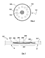
- Fig. 1 shows a cross-sectional view of an example of an optical core 101 which may be suitably jointed according to the present method.
- the optical core 101 comprises a central support, typically a central reinforcing member 104, coated with a thermoplastic polymeric layer 103.
- the central reinforcing member may be, for instance, a metal wire, e.g of steel.
- polymers suitable for coating the reinforcing member are thermoplastic resins such as an elastomeric polyester.
- polymers marketed under the trade name Hytrel®, e.g. Hytrel® 3548L (Du Pont) can be used.
- a plurality of optical fibres 102 are arranged longitudinally around the strength member 104 and are completely encapsulated into the polymeric layer 103.
- the number of optical fibers may be, for instance, from 2 to 24, preferably 6 to 12.
- the strength member is a steel wire with a diameter of between 0.5 and 0.7 mm, preferably of about 0.65 mm.
- the polymeric layer 103 encapsulating the optical fibres has a diameter of between 2.5 and 3 mm, preferably 2.75 mm.
- the optical core may comprise a further protective layer 105 of a plastic material, e.g. a sheath of thermoplastic material having a thickness of about 0.05-0.15 mm.
- a plastic material e.g. a sheath of thermoplastic material having a thickness of about 0.05-0.15 mm.
- the thermoplastic material is selected from those known in the art including, though the list is by no means exhaustive, polyamide and polyethylene and polypropylene.
- thermoplastic polymeric material embedding the optical fibers and the strength member of the respective end portions of the two different sections is removed according to conventional techniques, e.g. by manual removal and/or by melting of the polymeric material.
- the optical fibers and strength member of each end are exposed for a length of from about 30 to about 70 cm, typically for about 50 cm.
- the exposed optical fibers and the strength member of the first section are jointed with the respective exposed optical fibers and strength member of the second section.
- the strength member is jointed by any suitable conventional technique, for instance by means of a ferrule, e.g. a metal ferrule, preferably of stainless steel, which is crimped on the respective ends of the two strength members.
- a ferrule e.g. a metal ferrule, preferably of stainless steel, which is crimped on the respective ends of the two strength members.
- Optical fibers can be spliced together according to any suitable technique known in the art such as, for instance, fusing welding using any conventional splicing means.
- any suitable technique known in the art such as, for instance, fusing welding using any conventional splicing means.
- commercial automatic welder 40F from Fujikura can be used.
- the glass portion of the spliced optical fibers is then coated as known in the art, for Instance by applying a UV curable coating composition of the type used for secondary coating optical fibers, by using a conventional recoating device.
- a UV curable coating composition of the type used for secondary coating optical fibers
- DeSolite ® 950-111 from DSM can be applied as coating material, by using a Ericsson EFR 1000 recoater.
- the reverse order of splicing/jointing can be followed.
- the splicing/jointing step should however preferably result into a fiber length deficiency with respect to the length of the strength member, for avoiding possible fibers displacement during the application of the coating material.
- the resulting length of the spliced optical fibers is slightly shorter than the length of the jointed strength member, so that the fibers are subjected to a slight tension.
- the length of the spliced optical fibers is from about 0.01% to about 0.1% less than the length of the jointed strength member.
- Fig. 2 shows the two jointed sections A and A' of an optical core after the above operations, before the application of a polymeric coating 206 (represented by a dashed line) for completing the joint according to the method of the present invention.
- a polymeric coating 206 represented by a dashed line
- the respective end portions 201 and 201' of the two sections of the optical core are connected to each other through assembly 205 consisting of the respective exposed portions of the jointed strength member 202 (illustrated also with the crimped stainless steel ferrule 204 used for the jointing) and of the spliced optical fibers 203.
- Assembly 205 and polymeric coating 206 thus define a joint section 207 of the optical core 101.
- the length of the exposed plurality of optical fibers 203 and of the strength member 202 is of about 80-120 cm.
- the liquid curable composition to be applied on the exposed fibers and strength member to form the polymeric coating 206 should preferably have, at the application temperature, typically 25°C, a viscosity sufficiently high in order to avoid dripping phenomena during its application. On the other side, said viscosity should not be excessively high, in order to allow the composition to suitably flow through the conduits of the application device and to completely embed fibers and strength member.
- said coating composition will thus have a viscosity at 25°C of at least 1 Pas, more preferably of at least 5 Pas. Said viscosity is preferably not higher than 100 Pas, more preferably not higher than 50 Pas. According to a preferred embodiment, said viscosity is of about 10 Pas. Said viscosity is measured by means of a Bohlin viscometer in a plate-plate configuration, 40 mm diameter, shear rate 1 s -1 .
- the liquid curable composition to be applied on the exposed fibers and strength member is an acrylic based coating composition comprising at least one oligomer with acrylate or methacrylate terminal groups, at least one acrylic diluent monomer and at least one photoinitiator.
- the oligomer represents generally 40-80% of the formulation by weight and can be, for instance a polyurethaneacrylate, an epoxyacrylate or mixtures thereof.
- the acrylic type diluent monomer represents 20-50% and has a structure compatible with that of the oligomer.
- the diluent monomer can contain an alkyl structure, such as isobornylacrylate, hexanediacrylate, dicyclopentadiene-acrylate, trimethylolpropane-triacrylate, or aromatic such as nonylphenyletheracrylate, polyethyleneglycol-phenyletheracrylate and acrylic derivatives of bisphenol A.
- One or more photoinitiators are preferably added to the composition.
- Further additives such as inhibitors inhibiting polymerization by the effect of temperature, light stabilizers, levelling agents and detachment promotors can also be added.
- a typical formulation of a curable coating composition comprises about 40-70% of polyurethaneacrylate, epoxyacrylate or their mixtures, about 30-50% of diluent monomer, about 1-5% of photoinitiator and about 0.5-5% of other additives.
- the polymeric coating has preferably a modulus of elasticity E' at 25°C comparable to the one of the polymeric material forming the optical core.
- said modulus is not lower than about 1/3 of the modulus of the thermoplastic material, more preferably not lower than about 1 ⁇ 2 of said modulus.
- the modulus of the cured polymeric coating is preferably not higher than about five times the modulus of the thermoplastic material, more preferably not higher than about three times.
- the modulus of elasticity at 25°C of the cured polymeric material forming the joint can be from about 10 MPa to about 150 MPa, preferably from about 20 to about 90 MPa.
- the jointed optical core is employed for manufacturing a submarine telecommunication cable, typically having an operating temperature range from 0°C to about 20°C, it is preferable that said modulus of elasticity remains lower than about 1000 MPa along the whole of said temperature range, more preferably lower than about 800MPa and much more preferably not higher than about 600 MPa.
- the above modulus of elasticity is the tensile modulus of the material as measured using a DMTA apparatus (Dynamic Mechanical Thermal Analyser from Reometrics Inc.), in traction, at a frequency of 1 Hz and at a heating rate of 2°C/min.
- DMTA apparatus Dynamic Mechanical Thermal Analyser from Reometrics Inc.
- Figure 3 shows an apparatus 301 suitable for performing a jointing method and to obtain a jointed optical core according to the invention.
- the present method advantageously results into a joint having substantially the same diameter of the optical core.
- Said apparatus 301 is preferably mounted in a vertical position and comprises a pair of tensioning elements 302 and 302', each of which is provided with a respective fixing element 304 and 304', for fixing the jointed optical core.
- the apparatus also comprises a movable coating device 310 for forming the joint.
- the coating device comprises a carriage 305 which can slide on a guide 306 ending in correspondence with the pair of tensioning elements 302 and 302'.
- the said guide is preferably a very high-precision slide (the error of parallelism between the supporting plane and the plane on which the carriage slides is not more than ⁇ 5 ⁇ m) with a length of approximately 2 m.
- a mould 307 (illustrated in more detail in figure 4 ), is positioned on the said carriage 305.
- the mould is connected to a dispenser 308 for the radiation curable coating composition.
- Ultraviolet (UV) lamps 309 are arranged on opposite sides in the proximity of the mould 307 and are preferably Integral with the carriage 305.
- the carriage 305 is suitably driven by a motor (not shown) and is moved along the guide 306, preferably at a controlled speed, from one end to the other of the portion of fibers and strength member to be coated.
- the carriage is moved by means of an endless screw driven by an external motor.
- the endless screw rotates about itself and causes the movement of the carriage.
- the said motor is advantageously a very high-precision motor which does not cause vibrations, provides a constant speed, and reaches the working speed with a constant acceleration when starting and stopping.
- the value of the acceleration can be preset.
- the said characteristics of the motor avoid vibrations or abrupt movements which might adversely affect the quality of the coating.
- the mould is preferably moved along the elements to be coated at a speed of from about 0.1 to about 1.5 m/min, more preferably from about 0.3 m/min to about 1.0 m/min.
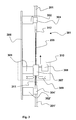
- Figures 4 shows in detail the mould 307, comprising two halves 401 and 402, which are preferably complementary to each other in such a way that they can be placed in contact one to each other to form a longitudinal internal cavity, through which the assembly of the strength member and optical fibers is then caused to pass through during the coating process.
- the central area of the cavity includes a chamber 403 with a cylindrical cross section for the accumulation of the material forming the coating, an entry channel 404 with a circular cross section for the insertion of the optical fibers and strength member and an exit channel 405 with a circular cross section through which the coated optical fibers and strength member emerge.
- the mould also comprises a channel 407 which introduces the liquid material (provided by the dispenser 308 shown in fig. 3 ) Into the accumulation chamber.
- Each of the two halves is preferably made of metallic material, or more generally of a material which is practically non-deformable at high temperatures and is capable of preventing the entry of ultraviolet light Into the mould.
- Entry and exit channels 404 and 405 are coaxial to a same axis, identified by the letter X in Figure 4 , in such a way that the assembly of the optical fibers and strength member is kept in a substantially rectilinear position.
- the entry channel 404 has preferably a diameter substantially equal (i.e. equal or up to about 0.2 mm larger) to the diameter of the optical core, while the exit channel 405 has a diameter slightly larger than the diameter of the optical core, preferably from about 0.1 to about 0.3 mm larger, in order to allow an overcoating of the integral portion of the optical core.
- the entry channel 404 has also a flare 406 which facilitates the insertion of the assembly 205 into the mould, so to avoid an abrupt positioning of the fibers which might cause damage to, or even fracture of, the fibers.
- the exit channel 405 may be provided with a similar flare, in order to allow a smooth release of the coated assembly from the mould.
- the device shown in Figure 3 operates in the following way.
- a jointed optical core (e.g. the one illustrated in fig. 2 ) is positioned into the device by fixing the two integer end portions 201 and 201' on the tensioning elements 302 and 302' through the respective fixing elements 304 and 304'.
- the tensioning elements are moved apart, so that the jointed strength member (and, accordingly, also the spliced optical fibers) of the assembly 205 remains under a slight tension during the coating process.
- a tension of from about 5 kg to about 10 kg is applied to the optical core, so that the strength member is subjected to an elongation of about 0.05-0.1%.
- the optical core has an outer sheath, as the sheath 105 illustrated in fig.
- a length of about 10-20 mm of said sheath can advantageously be removed, in order to expose the thermoplastic material embedding the optical fibers. Accordingly, the final portion of the fixed optical core 312 has a slightly reduced diameter, which facilitates the application of the coating material at the interface between the assembly 205 to be coated and the final portion of the integral optical core.
- the carriage 305 is placed at one end of the guide 306.
- a first half of the mould is placed on the said carriage in such a way that the assembly 205 is positioned exactly along the axis.
- the second half of the mould is placed In contact with the first half to form the complete mould.
- the assembly Is Inserted fully into the mould, and the liquid material is released by the dispenser 308 and passes through the channel 407 into the accumulation chamber 403 inside the mould, filling it completely.
- the coating material is subjected to radiation curing by means of the two UV lamps 309, thus obtaining a joint having substantially the same diameter as the one of the optical core.
- Fig. 3 illustrates a first portion 311 of the assembly 205 which has already been coated by coating device 310, which is moved in the direction of the arrow.
- the coating material is preferably superposed for a length of about 10-20 mm and a thickness of about 0.05-0.1 mm to the integral optical core. This slight superposition of the coating material onto the Integral optical core allows to fasten the coating material to the optical core and to avoid a possible coating discontinuity at the interfaces.
- a disk-like element having a plurality of holes for passing-through of fibers and strength member, can be inserted along the entry channel 404,
- This disk may be advantageously obtained by cutting a transversal section (e.g. 2-3 mm thickness) from the integral optical core, e.g. by cutting the end of one of the two integral optical cores after jointing of the same.
- the so obtained disk preferably deprived from the outer covering layer, is then caused to slide away from the integral end of the optical core and positioned within the mould, together with the assembly to be coated, in correspondence with the exit portion of the entry channel 404, as indicated by number 408 in fig. 4 .
- the mould at the end of the coating process, reaches the end of the opposite section of the integral optical core, the disk rests in contact with said integral portion and is coated by the coating material from the mould.
- the so obtained jointed optical core can thus be used to manufacture a substantial length of an optical cable, such as the cable 501 illustrated in fig. 5 .
- the cable 501 has an axis 510 and comprises centrally the optical core 101 which is substantially cylindrical and, around it, a plurality of protective and reinforcing elements or layers 507, 512 and 513.
- the optical core 101 described in detail above with reference to Figure 1 and jointed according to the above illustrated method, has an external diameter which is preferably less than 4 mm, typically of about 3 mm.
- this plurality of reinforcing elements comprises:
- the reinforcing elements 507c are arranged in an angular position corresponding to that of the reinforcing elements 507a so that the second reinforcing layer 509 has a substantially cylindrical external envelope tangential both to the reinforcing elements 507b and to the reinforcing elements 507c.
- the assembly consisting of the two reinforcing layers 508 and 509 defines a structure known in the art as a "Warrington" structure.
- a tubular lining 512 which is preferably made of metallic material and more preferably of copper, surrounds the reinforcing elements 507b, 507c of the second reinforcing layer 509 and, together with the abovementioned "Warrington" structure, defines a reinforcing structure having mechanical characteristics such as to provide the cable 501 with a high resistance to mechanical stresses, in particular to the hydrostatic pressure present in deep sea zones.
- the lining 512 defines an electrically conductive element which can be used for electrically supplying signal repeaters arranged in the telecommunications system of which the cable 501 forms a part.
- the lining 512 allows the innermost part to be protected from moisture.
- the reinforcing elements may be arranged in other configurations, i.e. in one or more rows, depending on the conditions of use.
- the cable 501 comprises, moreover, a layer 513 of polymer material, preferably polyethylene, which is arranged outside the lining 512 and designed to provide an electrical insulation with respect to the exterior.
- the external diameter of the layer 513 also defines the external diameter of the cable 501.
- the layer 513 may, if necessary, be protected by a metal-strip lining (not shown) or by one or more linings of the polymer type (not shown) outside the metal-layer lining.
- the cable 501 described above is typically designed to be used up to a maximum depth, at sea, of about 7000 m.
- the cable 501 may be provided with an external armouring (not shown) consisting of one or more layers of cylindrical reinforcing elements which are preferably made of steel and alternated with layers of polymer material, for example polypropylene.
Landscapes
- Physics & Mathematics (AREA)
- General Physics & Mathematics (AREA)
- Optics & Photonics (AREA)
- Mechanical Coupling Of Light Guides (AREA)
- Cable Accessories (AREA)
- Light Guides In General And Applications Therefor (AREA)
- Testing Of Short-Circuits, Discontinuities, Leakage, Or Incorrect Line Connections (AREA)
Claims (12)
- Ame optique pour câble de télécommunications, comprenant :- une première section et une deuxième section, lesquelles première et deuxième sections présentent sensiblement un même diamètre prédéterminé et comprennent respectivement un élément résistant central, un jeu de multiples fibres optiques, et un élément en un matériau polymère thermoplastique, disposé autour dudit élément résistant et dans lequel sont noyées lesdites fibres optiques ;- et une troisième section, située entre lesdites première et deuxième sections, et comprenant des épissures entre lesdites multiples fibres optiques et une jonction entre les éléments résistants desdites première et deuxième sections ;dans laquelle ladite troisième section comprend un matériau polymère durci, disposé autour desdits éléments résistants joints et desdites fibres optiques jointes par des épissures de manière à ce que ces éléments résistants et ces fibres optiques y soient noyés, laquelle troisième section présente sensiblement le même diamètre prédéterminé que lesdites première et deuxième sections de l'âme optique, et une longueur d'à peu près 80 à 120 cm.
- Ame optique conforme à la revendication 1, dans laquelle ledit matériau polymère durci présente un module d'élasticité qui vaut au moins à peu près le tiers du module d'élasticité dudit matériau thermoplastique.
- Ame optique conforme à la revendication 1, dans laquelle ledit matériau polymère durci présente un module d'élasticité qui vaut au moins à peu près la moitié du module d'élasticité dudit matériau thermoplastique.
- Ame optique conforme à la revendication 1, dans laquelle ledit matériau polymère durci présente un module d'élasticité qui vaut au plus à peu près le quintuple du module d'élasticité dudit matériau thermoplastique.
- Ame optique conforme à la revendication 1, dans laquelle ledit matériau polymère durci présente un module d'élasticité qui vaut au plus à peu près le triple du module d'élasticité dudit matériau thermoplastique.
- Câble optique comprenant une âme optique conforme à l'une des revendications 1 à 5, ainsi qu'au moins une gaine protectrice disposée autour de ladite âme optique.
- Procédé de raccordement d'une première section d'une âme optique pour câble de télécommunications à une deuxième section d'une âme optique pour câble de télécommunications, lesquelles première et deuxième sections d'âme optique présentent sensiblement un même diamètre prédéterminé et comprennent respectivement un élément résistant central, un jeu de multiples fibres optiques, et un élément en un matériau polymère thermoplastique, disposé autour dudit élément résistant et dans lequel sont noyées lesdites fibres optiques, lequel procédé comporte les étapes suivantes :- enlever le matériau polymère sur une longueur prédéterminée, à une extrémité de chacune desdites première et deuxième sections, de manière à mettre à nu les portions correspondantes des multiples fibres optiques des deux jeux et celles des deux éléments résistants ;- joindre par épissage les portions mises à nu respectives desdites multiples fibres optiques et raccorder les deux portions mises à nu des deux éléments résistants respectifs, ce qui fait qu'on obtient un assemblage d'une certaine longueur, formé par lesdites portions de fibres optiques mises à nu et jointes par épissage et par lesdites portions mises à nu et raccordées des éléments résistants, ledit assemblage étant long d'environ 80 à 120 cm ;- apporter sur toute la longueur dudit assemblage une composition liquide d'enduction, durcissable sous l'action d'un rayonnement ;- et faire durcir cette composition d'enduction durcissable sous l'action d'un rayonnement, afin d'obtenir un élément allongé de matériau polymère durci où sont noyés lesdites fibres optiques et lesdits éléments résistants, lequel élément allongé présente sensiblement le même diamètre prédéterminé que lesdites première et deuxième sections d'âme optique ;et dans lequel procédé l'on réalise ladite étape d'apport d'une composition liquide d'enduction, durcissable sous l'action d'un rayonnement, en faisant en sorte que celle-ci traverse, d'une première extrémité à une deuxième extrémité, un dispositif d'enduction placé sur toute la longueur dudit assemblage.
- Procédé conforme à la revendication 7, dans lequel ladite composition d'enduction présente, à 25 °C, une viscosité d'au moins 1 Pa.s.
- Procédé conforme à la revendication 7, dans lequel ladite composition d'enduction présente, à 25 °C, une viscosité d'au moins 5 Pa.s.
- Procédé conforme à la revendication 7, dans lequel ladite composition d'enduction présente, à 25 °C, une viscosité d'au plus 100 Pa.s.
- Procédé conforme à la revendication 7, dans lequel ladite composition d'enduction présente, à 25 °C, une viscosité qui, de préférence, vaut au plus 50 Pa.s.
- Procédé conforme à la revendication 7, dans lequel la longueur des fibres optiques jointes par épissage est inférieure, d'environ 0,01 % à environ 0,1 %, à la longueur de l'élément résistant.
Applications Claiming Priority (1)
| Application Number | Priority Date | Filing Date | Title |
|---|---|---|---|
| PCT/EP2002/012097 WO2004040347A1 (fr) | 2002-10-30 | 2002-10-30 | Cable de telecommunication comprenant un coeur optique raccorde et procede permettant de raccorder ledit coeur |
Publications (2)
| Publication Number | Publication Date |
|---|---|
| EP1556724A1 EP1556724A1 (fr) | 2005-07-27 |
| EP1556724B1 true EP1556724B1 (fr) | 2009-03-04 |
Family
ID=32241226
Family Applications (1)
| Application Number | Title | Priority Date | Filing Date |
|---|---|---|---|
| EP02791656A Expired - Lifetime EP1556724B1 (fr) | 2002-10-30 | 2002-10-30 | Cable de telecommunication comprenant un coeur optique raccorde et procede permettant de raccorder ledit coeur |
Country Status (8)
| Country | Link |
|---|---|
| US (1) | US7313303B2 (fr) |
| EP (1) | EP1556724B1 (fr) |
| AT (1) | ATE424571T1 (fr) |
| AU (1) | AU2002357993A1 (fr) |
| DE (1) | DE60231440D1 (fr) |
| ES (1) | ES2322139T3 (fr) |
| PT (1) | PT1556724E (fr) |
| WO (1) | WO2004040347A1 (fr) |
Cited By (1)
| Publication number | Priority date | Publication date | Assignee | Title |
|---|---|---|---|---|
| CN104865656A (zh) * | 2015-05-25 | 2015-08-26 | 江苏亨通高压电缆有限公司 | 一种不锈钢管光纤单元接头及其连接方法 |
Families Citing this family (16)
| Publication number | Priority date | Publication date | Assignee | Title |
|---|---|---|---|---|
| US20110231564A1 (en) * | 2000-09-25 | 2011-09-22 | Yevgeny Korsunsky | Processing data flows with a data flow processor |
| US7860364B2 (en) * | 2007-08-27 | 2010-12-28 | Tyco Electronics Corporation | Methods for accessing a fiber within a fiber optic cable to splice thereto and tools for use with the same |
| JP4458136B2 (ja) * | 2007-09-06 | 2010-04-28 | オムロン株式会社 | 有機デバイス、及び有機デバイスの製造方法 |
| US7926797B2 (en) | 2007-10-17 | 2011-04-19 | Adc Telecommunications, Inc. | Cable splint |
| EP2820732B1 (fr) * | 2012-02-29 | 2016-02-03 | ABB Technology Ltd. | Jonction comprenant deux sections d'un câble d'alimentation et procédé de jonction de deux sections d'un câble d'alimentation |
| US10215015B2 (en) | 2015-03-10 | 2019-02-26 | Halliburton Energy Services, Inc. | Strain sensitive optical fiber cable package for downhole distributed acoustic sensing |
| US10173381B2 (en) | 2015-03-10 | 2019-01-08 | Halliburton Energy Services, Inc. | Method of manufacturing a distributed acoustic sensing cable |
| WO2016144336A1 (fr) | 2015-03-10 | 2016-09-15 | Halliburton Energy Services Inc. | Système de surveillance de puits de forage mettant en œuvre un boîtier de câble à fibre optique sensible aux contraintes |
| EP3602155A1 (fr) | 2017-03-21 | 2020-02-05 | Corning Research & Development Corporation | Ensemble câble à fibres optiques avec épissure par fusion à sur-revêtement thermoplastique, et procédé et appareil associés |
| PL3847491T3 (pl) | 2018-09-07 | 2026-03-30 | Corning Incorporated | Zespół rozprowadzający włókna optyczne z interfejsem wstęgowanym do jednoczesnego zgrzewania sposobem fuzji oraz sposób wytwarzania |
| US10976492B2 (en) | 2018-09-07 | 2021-04-13 | Corning Incorporated | Cable with overcoated non-coplanar groups of fusion spliced optical fibers, and fabrication method |
| US11360265B2 (en) * | 2019-07-31 | 2022-06-14 | Corning Research & Development Corporation | Fiber optic cable assembly with overlapping bundled strength members, and fabrication method and apparatus |
| US11886009B2 (en) | 2020-10-01 | 2024-01-30 | Corning Research & Development Corporation | Coating fusion spliced optical fibers and subsequent processing methods thereof |
| US11808983B2 (en) | 2020-11-24 | 2023-11-07 | Corning Research & Development Corporation | Multi-fiber splice protector with compact splice-on furcation housing |
| US11867947B2 (en) | 2021-04-30 | 2024-01-09 | Corning Research & Development Corporation | Cable assembly having routable splice protectors |
| CN116689218B (zh) * | 2023-06-13 | 2026-01-09 | 芯体素(杭州)科技发展有限公司 | 一种微米级丝材分段自动涂敷打印装置及方法 |
Citations (1)
| Publication number | Priority date | Publication date | Assignee | Title |
|---|---|---|---|---|
| WO2001046080A2 (fr) * | 1999-12-22 | 2001-06-28 | Optical Technologies Italia S.P.A. | Procede et dispositif de revetement d'une fibre optique |
Family Cites Families (15)
| Publication number | Priority date | Publication date | Assignee | Title |
|---|---|---|---|---|
| US4367917A (en) * | 1980-01-17 | 1983-01-11 | Gray Stanley J | Multiple sheath cable and method of manufacture |
| EP0067673B1 (fr) * | 1981-06-17 | 1987-01-28 | British Telecommunications | Couplage de câbles à fibres optiques |
| US4647942A (en) * | 1981-11-20 | 1987-03-03 | Western Geophysical Co. | Circularly polarized antenna for satellite positioning systems |
| FR2524987A1 (fr) * | 1982-04-09 | 1983-10-14 | Cables De Lyon Geoffroy Delore | Dispositif de raccordement des extremites de deux cables sous-marins a fibres optiques et son procede de fabrication |
| GB2128357B (en) * | 1982-10-06 | 1986-05-21 | Standard Telephones Cables Ltd | Optical fibre cables |
| US4627942A (en) * | 1985-02-27 | 1986-12-09 | At&T Bell Laboratories | Method and apparatus for recoating spliced end portions of optical fibers |
| IT1183452B (it) * | 1985-03-01 | 1987-10-22 | Pirelli Cavi Spa | Giunti per cavi sottomarini di telecomunicazioni a fibre ottiche |
| IT1191732B (it) * | 1986-04-14 | 1988-03-23 | Pirelli Cavi Spa | Metodo per giuntare le estremita' di due elementi allungati provvisti di scanalature periferiche e giunzione cosi' ottenuta |
| JPS6416209A (en) * | 1987-07-09 | 1989-01-19 | Fujikura Ltd | Method of jointing plastic insulated cable |
| US5093048A (en) * | 1989-08-07 | 1992-03-03 | Grumman Aerospace Corporation | Rejacketing a spliced fiber optic cable |
| GB9301987D0 (en) * | 1993-02-02 | 1993-03-17 | Cable & Wireless Marine Ltd | Repairs to repeatered submarine communication cables |
| JPH08265932A (ja) * | 1995-03-23 | 1996-10-11 | Furukawa Electric Co Ltd:The | Cvケーブルの押出しモールドジョイント方法 |
| GB2331374A (en) * | 1997-11-18 | 1999-05-19 | Northern Telecom Ltd | A Removably Coated Optical Fibre |
| DE19909159C1 (de) * | 1999-03-02 | 2000-11-30 | Siemens Ag | Lichtwellenleiteranordnung |
| ES2312336T3 (es) * | 1999-03-31 | 2009-03-01 | Prysmian S.P.A. | Cable optico para telecomunicaciones. |
-
2002
- 2002-10-30 EP EP02791656A patent/EP1556724B1/fr not_active Expired - Lifetime
- 2002-10-30 PT PT02791656T patent/PT1556724E/pt unknown
- 2002-10-30 DE DE60231440T patent/DE60231440D1/de not_active Expired - Lifetime
- 2002-10-30 AU AU2002357993A patent/AU2002357993A1/en not_active Abandoned
- 2002-10-30 AT AT02791656T patent/ATE424571T1/de not_active IP Right Cessation
- 2002-10-30 ES ES02791656T patent/ES2322139T3/es not_active Expired - Lifetime
- 2002-10-30 WO PCT/EP2002/012097 patent/WO2004040347A1/fr not_active Ceased
- 2002-10-30 US US10/532,718 patent/US7313303B2/en not_active Expired - Fee Related
Patent Citations (1)
| Publication number | Priority date | Publication date | Assignee | Title |
|---|---|---|---|---|
| WO2001046080A2 (fr) * | 1999-12-22 | 2001-06-28 | Optical Technologies Italia S.P.A. | Procede et dispositif de revetement d'une fibre optique |
Cited By (2)
| Publication number | Priority date | Publication date | Assignee | Title |
|---|---|---|---|---|
| CN104865656A (zh) * | 2015-05-25 | 2015-08-26 | 江苏亨通高压电缆有限公司 | 一种不锈钢管光纤单元接头及其连接方法 |
| CN104865656B (zh) * | 2015-05-25 | 2018-04-17 | 江苏亨通海洋光网系统有限公司 | 一种不锈钢管光纤单元接头及其连接方法 |
Also Published As
| Publication number | Publication date |
|---|---|
| WO2004040347A1 (fr) | 2004-05-13 |
| ATE424571T1 (de) | 2009-03-15 |
| US7313303B2 (en) | 2007-12-25 |
| ES2322139T3 (es) | 2009-06-17 |
| EP1556724A1 (fr) | 2005-07-27 |
| DE60231440D1 (de) | 2009-04-16 |
| AU2002357993A1 (en) | 2004-05-25 |
| US20060127013A1 (en) | 2006-06-15 |
| PT1556724E (pt) | 2009-05-04 |
Similar Documents
| Publication | Publication Date | Title |
|---|---|---|
| EP1556724B1 (fr) | Cable de telecommunication comprenant un coeur optique raccorde et procede permettant de raccorder ledit coeur | |
| US5201020A (en) | Reinforced protective tube for optical waveguide fibers | |
| US7272282B1 (en) | Fiber optic cables and assemblies suitable for distribution | |
| US7330621B2 (en) | Flexible optical closure and other flexible optical assemblies | |
| US11347014B2 (en) | Optical fiber fan-out assembly with ribbonized interface for mass fusion splicing, and fabrication method | |
| WO2019005546A1 (fr) | Ensemble de distribution optique préterminé comportant un grand nombre de fibres | |
| US11808983B2 (en) | Multi-fiber splice protector with compact splice-on furcation housing | |
| EP2232318A1 (fr) | Fibre optique gainée et câble de télécommunication | |
| GB2296575A (en) | Fibre optic cable ,manufacturing process and plant | |
| US12230420B2 (en) | Stranded cable subunits with a central member for a bundled cable | |
| US5592579A (en) | Fiber optic cable splice and method for producing same | |
| AU2012285834B2 (en) | Method for extruding a drop cable | |
| EP4206774A1 (fr) | Élément de résistance intégré pour câbles à fibres optiques et son procédé de fabrication | |
| JPH0271207A (ja) | 光ファイバ用保護パイプ及びそれを用いてなる平型光ファイバコード | |
| JP2000155246A (ja) | 光海底ケーブル、光ファイバユニットおよびその製造方法 | |
| US20240427099A1 (en) | Overmold for optical fiber distribution cable and related method and system | |
| CN115917676A (zh) | 强度构件组件和结合有光纤的架空电缆 | |
| NZ620028B2 (en) | Method for extruding a drop cable |
Legal Events
| Date | Code | Title | Description |
|---|---|---|---|
| PUAI | Public reference made under article 153(3) epc to a published international application that has entered the european phase |
Free format text: ORIGINAL CODE: 0009012 |
|
| 17P | Request for examination filed |
Effective date: 20050502 |
|
| AK | Designated contracting states |
Kind code of ref document: A1 Designated state(s): AT BE BG CH CY CZ DE DK EE ES FI FR GB GR IE IT LI LU MC NL PT SE SK TR |
|
| AX | Request for extension of the european patent |
Extension state: AL LT LV MK RO SI |
|
| DAX | Request for extension of the european patent (deleted) | ||
| RAP1 | Party data changed (applicant data changed or rights of an application transferred) |
Owner name: PRYSMIAN CAVI E SISTEMI ENERGIA S.R.L. |
|
| 17Q | First examination report despatched |
Effective date: 20060908 |
|
| GRAP | Despatch of communication of intention to grant a patent |
Free format text: ORIGINAL CODE: EPIDOSNIGR1 |
|
| RAP1 | Party data changed (applicant data changed or rights of an application transferred) |
Owner name: PRYSMIAN S.P.A. |
|
| GRAS | Grant fee paid |
Free format text: ORIGINAL CODE: EPIDOSNIGR3 |
|
| GRAA | (expected) grant |
Free format text: ORIGINAL CODE: 0009210 |
|
| AK | Designated contracting states |
Kind code of ref document: B1 Designated state(s): AT BE BG CH CY CZ DE DK EE ES FI FR GB GR IE IT LI LU MC NL PT SE SK TR |
|
| REG | Reference to a national code |
Ref country code: GB Ref legal event code: FG4D |
|
| REG | Reference to a national code |
Ref country code: CH Ref legal event code: EP |
|
| REG | Reference to a national code |
Ref country code: IE Ref legal event code: FG4D |
|
| REF | Corresponds to: |
Ref document number: 60231440 Country of ref document: DE Date of ref document: 20090416 Kind code of ref document: P |
|
| REG | Reference to a national code |
Ref country code: PT Ref legal event code: SC4A Free format text: AVAILABILITY OF NATIONAL TRANSLATION Effective date: 20090423 |
|
| REG | Reference to a national code |
Ref country code: GR Ref legal event code: EP Ref document number: 20090401205 Country of ref document: GR |
|
| REG | Reference to a national code |
Ref country code: ES Ref legal event code: FG2A Ref document number: 2322139 Country of ref document: ES Kind code of ref document: T3 |
|
| PG25 | Lapsed in a contracting state [announced via postgrant information from national office to epo] |
Ref country code: FI Free format text: LAPSE BECAUSE OF FAILURE TO SUBMIT A TRANSLATION OF THE DESCRIPTION OR TO PAY THE FEE WITHIN THE PRESCRIBED TIME-LIMIT Effective date: 20090304 |
|
| PG25 | Lapsed in a contracting state [announced via postgrant information from national office to epo] |
Ref country code: SE Free format text: LAPSE BECAUSE OF FAILURE TO SUBMIT A TRANSLATION OF THE DESCRIPTION OR TO PAY THE FEE WITHIN THE PRESCRIBED TIME-LIMIT Effective date: 20090604 Ref country code: AT Free format text: LAPSE BECAUSE OF FAILURE TO SUBMIT A TRANSLATION OF THE DESCRIPTION OR TO PAY THE FEE WITHIN THE PRESCRIBED TIME-LIMIT Effective date: 20090304 |
|
| PG25 | Lapsed in a contracting state [announced via postgrant information from national office to epo] |
Ref country code: CZ Free format text: LAPSE BECAUSE OF FAILURE TO SUBMIT A TRANSLATION OF THE DESCRIPTION OR TO PAY THE FEE WITHIN THE PRESCRIBED TIME-LIMIT Effective date: 20090304 Ref country code: EE Free format text: LAPSE BECAUSE OF FAILURE TO SUBMIT A TRANSLATION OF THE DESCRIPTION OR TO PAY THE FEE WITHIN THE PRESCRIBED TIME-LIMIT Effective date: 20090304 |
|
| PG25 | Lapsed in a contracting state [announced via postgrant information from national office to epo] |
Ref country code: SK Free format text: LAPSE BECAUSE OF FAILURE TO SUBMIT A TRANSLATION OF THE DESCRIPTION OR TO PAY THE FEE WITHIN THE PRESCRIBED TIME-LIMIT Effective date: 20090304 |
|
| PLBE | No opposition filed within time limit |
Free format text: ORIGINAL CODE: 0009261 |
|
| STAA | Information on the status of an ep patent application or granted ep patent |
Free format text: STATUS: NO OPPOSITION FILED WITHIN TIME LIMIT |
|
| PG25 | Lapsed in a contracting state [announced via postgrant information from national office to epo] |
Ref country code: BG Free format text: LAPSE BECAUSE OF FAILURE TO SUBMIT A TRANSLATION OF THE DESCRIPTION OR TO PAY THE FEE WITHIN THE PRESCRIBED TIME-LIMIT Effective date: 20090604 Ref country code: DK Free format text: LAPSE BECAUSE OF FAILURE TO SUBMIT A TRANSLATION OF THE DESCRIPTION OR TO PAY THE FEE WITHIN THE PRESCRIBED TIME-LIMIT Effective date: 20090304 |
|
| 26N | No opposition filed |
Effective date: 20091207 |
|
| PGFP | Annual fee paid to national office [announced via postgrant information from national office to epo] |
Ref country code: NL Payment date: 20091024 Year of fee payment: 8 |
|
| PGFP | Annual fee paid to national office [announced via postgrant information from national office to epo] |
Ref country code: PT Payment date: 20091015 Year of fee payment: 8 |
|
| PG25 | Lapsed in a contracting state [announced via postgrant information from national office to epo] |
Ref country code: MC Free format text: LAPSE BECAUSE OF NON-PAYMENT OF DUE FEES Effective date: 20091031 |
|
| REG | Reference to a national code |
Ref country code: CH Ref legal event code: PL |
|
| PGFP | Annual fee paid to national office [announced via postgrant information from national office to epo] |
Ref country code: GR Payment date: 20091030 Year of fee payment: 8 |
|
| PG25 | Lapsed in a contracting state [announced via postgrant information from national office to epo] |
Ref country code: LI Free format text: LAPSE BECAUSE OF NON-PAYMENT OF DUE FEES Effective date: 20091031 Ref country code: CH Free format text: LAPSE BECAUSE OF NON-PAYMENT OF DUE FEES Effective date: 20091031 Ref country code: IE Free format text: LAPSE BECAUSE OF NON-PAYMENT OF DUE FEES Effective date: 20091030 |
|
| PGFP | Annual fee paid to national office [announced via postgrant information from national office to epo] |
Ref country code: FR Payment date: 20101105 Year of fee payment: 9 |
|
| PGFP | Annual fee paid to national office [announced via postgrant information from national office to epo] |
Ref country code: DE Payment date: 20101027 Year of fee payment: 9 |
|
| PGFP | Annual fee paid to national office [announced via postgrant information from national office to epo] |
Ref country code: IT Payment date: 20101026 Year of fee payment: 9 Ref country code: GB Payment date: 20101025 Year of fee payment: 9 Ref country code: TR Payment date: 20101005 Year of fee payment: 9 Ref country code: BE Payment date: 20101026 Year of fee payment: 9 |
|
| PG25 | Lapsed in a contracting state [announced via postgrant information from national office to epo] |
Ref country code: LU Free format text: LAPSE BECAUSE OF NON-PAYMENT OF DUE FEES Effective date: 20091030 |
|
| REG | Reference to a national code |
Ref country code: PT Ref legal event code: MM4A Free format text: LAPSE DUE TO NON-PAYMENT OF FEES Effective date: 20110502 |
|
| REG | Reference to a national code |
Ref country code: NL Ref legal event code: V1 Effective date: 20110501 |
|
| PGFP | Annual fee paid to national office [announced via postgrant information from national office to epo] |
Ref country code: ES Payment date: 20101026 Year of fee payment: 9 |
|
| PG25 | Lapsed in a contracting state [announced via postgrant information from national office to epo] |
Ref country code: PT Free format text: LAPSE BECAUSE OF NON-PAYMENT OF DUE FEES Effective date: 20110502 Ref country code: GR Free format text: LAPSE BECAUSE OF NON-PAYMENT OF DUE FEES Effective date: 20110503 |
|
| PG25 | Lapsed in a contracting state [announced via postgrant information from national office to epo] |
Ref country code: NL Free format text: LAPSE BECAUSE OF NON-PAYMENT OF DUE FEES Effective date: 20110501 |
|
| PG25 | Lapsed in a contracting state [announced via postgrant information from national office to epo] |
Ref country code: CY Free format text: LAPSE BECAUSE OF FAILURE TO SUBMIT A TRANSLATION OF THE DESCRIPTION OR TO PAY THE FEE WITHIN THE PRESCRIBED TIME-LIMIT Effective date: 20090304 |
|
| BERE | Be: lapsed |
Owner name: PRYSMIAN S.P.A. Effective date: 20111031 |
|
| GBPC | Gb: european patent ceased through non-payment of renewal fee |
Effective date: 20111030 |
|
| REG | Reference to a national code |
Ref country code: FR Ref legal event code: ST Effective date: 20120629 |
|
| PG25 | Lapsed in a contracting state [announced via postgrant information from national office to epo] |
Ref country code: BE Free format text: LAPSE BECAUSE OF NON-PAYMENT OF DUE FEES Effective date: 20111031 Ref country code: DE Free format text: LAPSE BECAUSE OF NON-PAYMENT OF DUE FEES Effective date: 20120501 |
|
| REG | Reference to a national code |
Ref country code: DE Ref legal event code: R119 Ref document number: 60231440 Country of ref document: DE Effective date: 20120501 |
|
| PG25 | Lapsed in a contracting state [announced via postgrant information from national office to epo] |
Ref country code: FR Free format text: LAPSE BECAUSE OF NON-PAYMENT OF DUE FEES Effective date: 20111102 Ref country code: GB Free format text: LAPSE BECAUSE OF NON-PAYMENT OF DUE FEES Effective date: 20111030 Ref country code: IT Free format text: LAPSE BECAUSE OF NON-PAYMENT OF DUE FEES Effective date: 20111030 |
|
| REG | Reference to a national code |
Ref country code: ES Ref legal event code: FD2A Effective date: 20131023 |
|
| PG25 | Lapsed in a contracting state [announced via postgrant information from national office to epo] |
Ref country code: TR Free format text: LAPSE BECAUSE OF NON-PAYMENT OF DUE FEES Effective date: 20111030 |
|
| PG25 | Lapsed in a contracting state [announced via postgrant information from national office to epo] |
Ref country code: ES Free format text: LAPSE BECAUSE OF NON-PAYMENT OF DUE FEES Effective date: 20111031 |