EP1556923B1 - Antenne dynamique - Google Patents
Antenne dynamique Download PDFInfo
- Publication number
- EP1556923B1 EP1556923B1 EP02789044.1A EP02789044A EP1556923B1 EP 1556923 B1 EP1556923 B1 EP 1556923B1 EP 02789044 A EP02789044 A EP 02789044A EP 1556923 B1 EP1556923 B1 EP 1556923B1
- Authority
- EP
- European Patent Office
- Prior art keywords
- antenna
- impedance
- arrangement
- during
- antenna arrangement
- Prior art date
- Legal status (The legal status is an assumption and is not a legal conclusion. Google has not performed a legal analysis and makes no representation as to the accuracy of the status listed.)
- Expired - Lifetime
Links
- 238000000034 method Methods 0.000 claims description 12
- 230000005540 biological transmission Effects 0.000 claims description 6
- 238000009434 installation Methods 0.000 claims description 4
- 230000000737 periodic effect Effects 0.000 claims 3
- 238000002592 echocardiography Methods 0.000 claims 2
- 230000001678 irradiating effect Effects 0.000 claims 2
- 230000001960 triggered effect Effects 0.000 claims 2
- 230000000694 effects Effects 0.000 description 4
- 210000000554 iris Anatomy 0.000 description 4
- 230000009467 reduction Effects 0.000 description 4
- 230000004913 activation Effects 0.000 description 2
- 230000001419 dependent effect Effects 0.000 description 2
- 238000010586 diagram Methods 0.000 description 2
- 230000008859 change Effects 0.000 description 1
- 238000004891 communication Methods 0.000 description 1
- 230000003247 decreasing effect Effects 0.000 description 1
- 230000002708 enhancing effect Effects 0.000 description 1
- 230000001939 inductive effect Effects 0.000 description 1
- 238000012986 modification Methods 0.000 description 1
- 230000004048 modification Effects 0.000 description 1
- 230000004044 response Effects 0.000 description 1
- 238000009966 trimming Methods 0.000 description 1
Images



Classifications
-
- G—PHYSICS
- G01—MEASURING; TESTING
- G01S—RADIO DIRECTION-FINDING; RADIO NAVIGATION; DETERMINING DISTANCE OR VELOCITY BY USE OF RADIO WAVES; LOCATING OR PRESENCE-DETECTING BY USE OF THE REFLECTION OR RERADIATION OF RADIO WAVES; ANALOGOUS ARRANGEMENTS USING OTHER WAVES
- G01S7/00—Details of systems according to groups G01S13/00, G01S15/00, G01S17/00
- G01S7/02—Details of systems according to groups G01S13/00, G01S15/00, G01S17/00 of systems according to group G01S13/00
- G01S7/03—Details of HF subsystems specially adapted therefor, e.g. common to transmitter and receiver
-
- H—ELECTRICITY
- H01—ELECTRIC ELEMENTS
- H01Q—ANTENNAS, i.e. RADIO AERIALS
- H01Q13/00—Waveguide horns or mouths; Slot antennas; Leaky-waveguide antennas; Equivalent structures causing radiation along the transmission path of a guided wave
- H01Q13/06—Waveguide mouths
-
- H—ELECTRICITY
- H01—ELECTRIC ELEMENTS
- H01Q—ANTENNAS, i.e. RADIO AERIALS
- H01Q17/00—Devices for absorbing waves radiated from an antenna; Combinations of such devices with active antenna elements or systems
-
- H—ELECTRICITY
- H01—ELECTRIC ELEMENTS
- H01Q—ANTENNAS, i.e. RADIO AERIALS
- H01Q23/00—Antennas with active circuits or circuit elements integrated within them or attached to them
-
- H—ELECTRICITY
- H01—ELECTRIC ELEMENTS
- H01Q—ANTENNAS, i.e. RADIO AERIALS
- H01Q9/00—Electrically-short antennas having dimensions not more than twice the operating wavelength and consisting of conductive active radiating elements
- H01Q9/04—Resonant antennas
- H01Q9/0407—Substantially flat resonant element parallel to ground plane, e.g. patch antenna
-
- H—ELECTRICITY
- H01—ELECTRIC ELEMENTS
- H01Q—ANTENNAS, i.e. RADIO AERIALS
- H01Q9/00—Electrically-short antennas having dimensions not more than twice the operating wavelength and consisting of conductive active radiating elements
- H01Q9/04—Resonant antennas
- H01Q9/0407—Substantially flat resonant element parallel to ground plane, e.g. patch antenna
- H01Q9/0442—Substantially flat resonant element parallel to ground plane, e.g. patch antenna with particular tuning means
Definitions
- the present invention relates to antennas for radar systems or communication systems, and more specifically how to effectively reduce the antenna radar cross section for enabling stealth performance.
- a well-known problem within antenna techniques is how to effectively reduce the radar cross section of an antenna with a minimum effect on antenna performance to thereby enable a stealth performance.
- One way to circumvent the problem of course is to not use any antennas at all, like for instance the known F117 aircraft.
- Another possibility is shielding the antenna by means of external frequency selective surfaces (FSS).
- FSS external frequency selective surfaces
- a third possibility would be to turn away the antenna. However, a turned away antenna can not be used until it is turned back again to the proper direction, which gives an unwanted important negative time factor.
- Prior art also mentions switched curtains or radomes to be placed in front of an antenna.
- an U.S. Patent No. 4,682,176 describes an active transmit/receive module that provides selectable impedance matching between the antenna and the feed lines.
- the module can be programmed to select a specific impedance when transmitting and another one when receiving.
- U.S. Patent No. 5,129,099 discloses a tranceiver solution for a radar antenna (array) where one (hybrid mode) phase shifter is used for transmit operations and another for receive operations.
- U.S. Patent No. 4,117,485 describes a method for reducing, or enhancing, the radar cross section (RCS) by using a load impedance, which may be tuned.
- WO 02/11239 discloses a multiple band reconfigurable reflecting antenna array and a method for multiple band operation and beam steering.
- An array of dipole antennas is disposed on a multiple band high impedance surface.
- the antenna array is re-configured by changing the length of the dipole elements, to thereby change the resonant frequency of the dipoles.
- small changes in dipole length allow to steer the reflected beam in a selected direction, while large changes in dipole length result in a switch of operating frequency band.
- the U.S. Patent No. 3,568,194 from 1967 discusses a way in which a return signal can be degraded by using a variable transmission load connected to the reflector.
- the disclosed method and system comprise phase and/or amplitude modulation of the radar signal by one or more "scattering" sources positioned on a target vehicle, thus causing the return target signal to appear as an incoherent object.
- an U.S. Patent No. 5,153,594 discloses an electronic countermeasure system for installation on an aircraft.
- the system includes an interferometer transmitter comprising a plurality of repeater amplifier circuits connected in parallel.
- the plurality of repeater amplifier circuits generate out of phase signals of different amplitudes, which are respectively transmitted by associated spaced transmitting antennas on the aircraft as response to an incoming radar signal.
- the scattering from an antenna element depends on the impedance load of the antenna element, i.e. the degree of mismatch (reflection coefficient in amplitude and phase). According to the invention this impedance load is dynamically changed according to the requirements in a particular situation.
- the first case is when a transmitting pulse is radiated through the antenna.
- the second case is when a reflected pulse from a target is received.
- the antenna is of no use.
- the RCS reduction typically leads to an antenna gain reduction as well. This can often be accepted in receive mode, since the competing noise etc in real situations is external to the system, and thus reduced as much as the useful signal. It would therefore be sufficient to "fully open” the antenna only during the transmit pulse, in order not to lose transmit power.
- the antenna is "fully opened”, i.e. completely matched only when needed, preferably during a transmit pulse, and "trade-off matched” otherwise.
- "trade-off matched” it exhibits low scattering. In an interval of not transmitting or receiving the antenna could preferably be "closed”.
- a particular implementation makes use of the high voltage in the transmit pulse, causing a gas discharge as in transmit/receive (TR) tubes. This effects automatically the impedance shift, which will then "open" the antenna.
- the present invention will enable for instance a fighter aircraft to operate with a minimum risk of being observed by other radar equipment. Still maximum utilization of the aircraft's own radar may instantly take place.
- a method according to the present invention is set forth by the independent claim 1, and further embodiments of the invention are set forth by the dependent claims 2 to 7.
- a reduction of the radar cross section (RCS) by adjusting the impedance load typically leads to an antenna gain reduction since a mismatch in the feed lines constitutes a loss.
- Figure 1 illustrates in a simple block diagram a device for reducing radar cross section of an antenna arrangement used for a radar installation provided with a pulsed transmitter and a generally gated receiver.
- a control unit controls an impedance element, which acts as a controlled impedance generally forming an inner tuning device of the antenna arrangement.
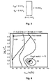
- FIG. 2 shows an antenna arrangement consisting of a waveguide opening in a ground plane.
- the waveguide opening may be matched by means of an iris, here chosen to be inductive, with an opening c ind positioned at a distance d bl from the waveguide opening.
- iris here chosen to be inductive
- the quality of a matching can be measured by a parameter referred to as S11, which is the reflection factor. Normally values of -10 to -15 dB are desired.
- Figures 4 and 5 the trade-off for a single element is illustrated.
- Figure 4 illustrates the influence on the matching (parameter S11) while
- Figure 5 illustrates the radar cross section in dB over a square meter (dB sm ) when c ind and d bl are varied.
- An optimal point is found by following a direction, which does not increase S11, i.e. along a level curve, and at the same time going across the level lines of the radar cross section ("steepest decent").
- a good matching is obtained in the little area pointed to by the rightmost arrow in Figure 4 .
- a poor match is obtained along the left portion of the graph.
- the corresponding radar cross section is demonstrated in Figure 5 .
- a very low or a very high RCS may be obtained depending on the position of a short-circuit.
- a low radar cross section is achieved both down to the left and up to the left in Figure 5 .
- the short-circuit is placed a distance ⁇ g /2 down the waveguide, which explains the low RCS for this case.
- a shorted waveguide is not acceptable but an iris with an opening of about 33%, placed close to the aperture, reduces the RCS by about 15 dB compared to the best matched case according to Figure 4 .
- the aperture is left fully open reducing the radar cross section by 5 dB.
- the first example gives a S11 of about -1dB, i.e. a loss due to a mismatch of 7 dB. That could generally be tolerated in the case of reception when using a suitable transmitting power.
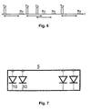
- FIG. 6 illustrates radar transmit pulses as a function of time and investigating a target at a certain range indicated by the horizontal arrows. As can be seen from Figure 6 the pulse repetition rate in a preferred embodiment is continuously varied to prevent simple synchronization by hostile radar equipment.
- One example is one or more diodes, which are made conducting or being reversed biased.
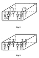
- the diodes are positioned across the waveguide 5 illustrated in Figure 7 and can provide the desired controlled impedance load, when made to conduct.
- FIG. 7 illustrates a tuning device, which is activated when its components 10 are activated, here illustrated as diodes, which are forced to conduct.
- diodes When reverse biasing the diodes, those will generally be capacitive and only impose a smaller effect, while when conducting they will represent a shorted portion of the waveguide cross section. This function can be taken into account in the design by further trimmings.
- Figures 8 and 9 demonstrate a further embodiment having the impedance load divided into two portions, which may be activated one by one or simultaneously. Activation may be by reverse biasing or forward biasing the elements 10 and 12.
- the iris formed by elements 10 is positioned close to the aperture of a waveguide as previously discussed.
- Figure 10 illustrates in a top view an embodiment having the impedance load divided into three spaced portions 10, 12 and 14.
- a first fully matched state for transmission a second "trade-off matched" state for reception providing a lower RCS for a hostile radar and finally a third state with the antenna "closed” providing a lowest possible RCS of the antenna.
- the bias voltage of the diodes are for instance commanded in synchronism with the triggering of the transmitting or receiving events.
- the impedance load component could in certain cases for instance be replaced by gas discharge tubes, which automatically will be “ignited” by the transmit pulse itself and thereby match the antenna arrangement to present a low loss for the transmit pulse.
- the system according to the present invention enables for instance a fighter or reconnaissance aircraft to operate without being too easily observed by other radar facilities. Still full use of the own radar of the aircraft may take place.
Landscapes
- Engineering & Computer Science (AREA)
- Computer Networks & Wireless Communication (AREA)
- Physics & Mathematics (AREA)
- General Physics & Mathematics (AREA)
- Radar, Positioning & Navigation (AREA)
- Remote Sensing (AREA)
- Radar Systems Or Details Thereof (AREA)
Claims (13)
- Procédé de réduction d'une surface équivalente radar d'un agencement d'antenne, caractérisé par l'étape consistant à commander dynamiquement la charge d'impédance de l'agencement d'antenne en vue de réduire par conséquent la dispersion d'un signal provenant d'une source externe irradiant l'agencement d'antenne, dans lequel l'étape de commande dynamique de la charge d'impédance comprend l'étape consistant à modifier un coefficient de réflexion (S11) de l'agencement d'antenne en mettant en oeuvre les étapes ci-dessous consistant à :- adapter totalement la charge d'impédance de l'agencement d'antenne au cours d'une période de transmission comprenant une impulsion de transmission provenant de l'agencement d'antenne ;- obtenir au moins une adaptation par compromis de la charge d'impédance de l'agencement d'antenne au cours d'une période de réception définie ; et- fournir une adaptation médiocre de la charge d'impédance de l'agencement d'antenne au cours d'une période de temps inactive excluant les périodes de réception et de transmission ;ladite étape de commande de la charge d'impédance comprenant la commande d'un diaphragme avec une ouverture positionnée à une certaine distance d'une ouverture de guide d'ondes, ledit diaphragme fournissant une relation entre la charge d'impédance et la surface équivalente radar de l'agencement d'antenne ;
moyennant quoi l'agencement d'antenne présentera une surface équivalente radar faible au cours de ladite période inactive. - Procédé selon la revendication 1, caractérisé par les étapes supplémentaires ci-dessous consistant à :déclencher, à des intervalles non périodiques, la charge d'impédance commandée dynamiquement de l'agencement d'antenne par une impulsion de transmission, en vue d'obtenir une adaptation de fréquence complète, et par conséquent une faible perte de puissance au cours de l'impulsion de transmission ; etdéclencher, à des intervalles non périodiques correspondant à une fenêtre de plage désirée, la charge d'impédance commandée dynamiquement sur une adaptation par compromis pour la réception d'échos à une distance souhaitée, réduisant activement toute dispersion indésirable de l'agencement d'antenne au cours de toutes les autres périodes.
- Procédé selon la revendication 2, caractérisé par l'étape supplémentaire ci-dessous consistant à :générer l'impédance commandée dynamiquement au moyen d'au moins un dispositif de syntonisation interne commandé, en commandant le dispositif de syntonisation interne au cours de périodes de réception et de transmission ainsi qu'au cours de la période sans transmission ou réception active.
- Procédé selon la revendication 3, caractérisé par l'étape supplémentaire ci-dessous consistant à :créer le dispositif de syntonisation interne en utilisant un agencement à commutation d'impédance (10) qui est commuté de manière appropriée en vue de fournir une conductivité totale ou partielle au cours de phases respectives de fonctionnement, et une partie propre de l'agencement d'impédance qui est non conductrice le reste du temps.
- Procédé selon la revendication 3, caractérisé par l'étape supplémentaire ci-dessous consistant à :créer le dispositif de syntonisation interne au moyen d'un agencement d'impédance (10) présentant une partie dotée d'au moins une diode (10) qui est polarisée en sens direct au cours d'au moins une phase de transmission, et une seconde partie (12) dotée d'au moins une diode (12) de l'agencement d'impédance qui est polarisée en sens direct le reste du temps.
- Procédé selon la revendication 3, caractérisé par l'étape supplémentaire ci-dessous consistant à :créer un dispositif de syntonisation interne au moyen d'un agencement d'impédance qui représente au moins un tube à décharge gazeuse enflammé par l'impulsion de transmission.
- Procédé selon la revendication 1, caractérisé par l'étape supplémentaire ci-dessous consistant à :créer, au moyen de la charge d'impédance de l'agencement d'antenne, un premier état qui est entièrement adapté pour la transmission, un deuxième état qui est « adapté par compromis » pour la réception, offrant une surface équivalente radar d'antenne inférieure, et un troisième état où l'antenne est « fermée », fournissant une surface équivalente radar la plus faible possible de l'antenne lorsqu'elle n'est pas utilisée.
- Agencement d'antenne (dynamique) destiné à réduire une surface équivalente radar, ledit agencement d'antenne (dynamique) comprenant une antenne dans une installation de radar, caractérisé en ce que l'agencement d'antenne comprend :- une unité de commande connectée à un agencement d'impédance, l'unité de commande commandant dynamiquement la charge d'impédance de l'agencement d'antenne en vue de réduire par conséquent la dispersion d'un signal provenant d'une source externe irradiant l'agencement d'antenne ;- l'agencement d'impédance est connecté à l'antenne, dans lequel la charge d'impédance de l'agencement d'antenne est commandée en modifiant un coefficient de réflexion de l'agencement d'antenne entre :- une adaptation totale de la charge d'impédance de l'agencement d'antenne au cours d'une période de transmission comprenant une impulsion de transmission provenant d'un émetteur dans l'agencement d'antenne ;- au moins une adaptation par compromis de la charge d'impédance de l'agencement d'antenne au cours d'une période de réception définie dans l'agencement d'antenne ; et- une adaptation médiocre de la charge d'impédance de l'agencement d'antenne au cours d'une période de temps inactive excluant les périodes de réception et de transmission ;- ledit agencement d'impédance comprenant en outre un diaphragme avec une ouverture positionnée à une certaine distance d'une ouverture de guide d'ondes, ledit diaphragme fournissant une relation entre la charge d'impédance et la surface équivalente radar de l'agencement d'antenne ;moyennant quoi l'agencement d'antenne présente une surface équivalente radar faible au cours de ladite période inactive.
- Antenne dynamique selon la revendication 8, caractérisée en ce que
la charge d'impédance commandée dynamiquement est déclenchée, à des intervalles non périodiques, par une impulsion de transmission destinée à obtenir une adaptation de fréquence complète et par conséquent une faible perte de puissance au cours de l'impulsion de transmission ; et
la charge d'impédance commandée dynamiquement est déclenchée, à une fenêtre de plage désirée, sur au moins une adaptation par compromis pour la réception d'échos à une distance souhaitée, de manière à réduire activement par conséquent la dispersion indésirable provenant de l'agencement d'antenne au cours de la réception, et à réduire une surface équivalente radar de l'antenne au cours de périodes inactives en l'absence de transmission ou de réception. - Antenne dynamique selon la revendication 9, caractérisée en ce que
l'impédance commandée dynamiquement est formée au moyen d'au moins un dispositif de syntonisation interne commandé qui peut être commandé au cours de périodes de réception et de transmission, ainsi qu'au cours d'une période sans transmission ou réception active. - Antenne dynamique selon la revendication 10, caractérisée en ce que
le dispositif de syntonisation interne est formé par au moins un agencement à commutation d'impédance (10) qui peut être commuté sur une conductivité partielle ou totale au cours de phases respectives de fonctionnement et peut être commuté sur un état de fermeture de l'antenne le reste du temps. - Antenne dynamique selon la revendication 10, caractérisée en ce que
le dispositif de syntonisation interne formant l'agencement d'impédance (10) représente au moins une diode, qui est polarisée en sens direct au cours d'une phase active de fonctionnement et est polarisée en sens indirect le reste du temps. - Antenne dynamique selon la revendication 10, caractérisée en ce que
le dispositif de syntonisation interne formant l'agencement d'impédance représente au moins un tube à décharge gazeuse qui est enflammé par l'impulsion de transmission.
Applications Claiming Priority (1)
| Application Number | Priority Date | Filing Date | Title |
|---|---|---|---|
| PCT/SE2002/001943 WO2004038863A1 (fr) | 2002-10-24 | 2002-10-24 | Antenne dynamique |
Publications (2)
| Publication Number | Publication Date |
|---|---|
| EP1556923A1 EP1556923A1 (fr) | 2005-07-27 |
| EP1556923B1 true EP1556923B1 (fr) | 2013-05-15 |
Family
ID=32173638
Family Applications (1)
| Application Number | Title | Priority Date | Filing Date |
|---|---|---|---|
| EP02789044.1A Expired - Lifetime EP1556923B1 (fr) | 2002-10-24 | 2002-10-24 | Antenne dynamique |
Country Status (4)
| Country | Link |
|---|---|
| US (1) | US7202807B2 (fr) |
| EP (1) | EP1556923B1 (fr) |
| AU (1) | AU2002353683A1 (fr) |
| WO (1) | WO2004038863A1 (fr) |
Families Citing this family (5)
| Publication number | Priority date | Publication date | Assignee | Title |
|---|---|---|---|---|
| GB201213294D0 (en) * | 2012-07-23 | 2013-07-24 | Secr Defence | Phased array antenna |
| JP6292758B2 (ja) * | 2013-03-07 | 2018-03-14 | 三菱電機株式会社 | アンテナ装置 |
| FR3003700B1 (fr) * | 2013-03-19 | 2016-07-22 | Thales Sa | Dispositif de reduction de signature radar d'antenne et systeme antennaire associe |
| WO2014178125A1 (fr) * | 2013-04-30 | 2014-11-06 | 古河電気工業株式会社 | Appareil radar |
| CN113964548A (zh) * | 2021-10-25 | 2022-01-21 | 电子科技大学 | 一种基于四维天线阵的带内散射缩减结构及其控制方法 |
Citations (3)
| Publication number | Priority date | Publication date | Assignee | Title |
|---|---|---|---|---|
| US4155087A (en) * | 1973-04-20 | 1979-05-15 | The United States Of America As Represented By The Secretary Of The Army | Radar receiver for detecting coded information buried in radar echoes |
| US4684952A (en) * | 1982-09-24 | 1987-08-04 | Ball Corporation | Microstrip reflectarray for satellite communication and radar cross-section enhancement or reduction |
| US5129099A (en) * | 1989-03-30 | 1992-07-07 | Electromagnetic Sciences, Inc. | Reciprocal hybrid mode rf circuit for coupling rf transceiver to an rf radiator |
Family Cites Families (13)
| Publication number | Priority date | Publication date | Assignee | Title |
|---|---|---|---|---|
| US3568194A (en) * | 1967-10-11 | 1971-03-02 | Us Air Force | System for degrading radar return signals |
| US4117485A (en) * | 1971-01-05 | 1978-09-26 | The United States Of America As Represented By The Secretary Of The Air Force | Radar target cross section control method and means |
| US5153594A (en) * | 1973-04-16 | 1992-10-06 | Moffat William V | Electronic counter-measure system for aircraft |
| US4682176A (en) * | 1986-03-12 | 1987-07-21 | The United States Of America As Represented By The Secretary Of The Air Force | Active matching transmit/receive module |
| DE3722793A1 (de) * | 1987-07-10 | 1989-01-19 | Licentia Gmbh | Radartarnmaterial |
| US4989006A (en) * | 1989-10-17 | 1991-01-29 | The United States Of America As Represented By The Secretary Of The Air Force | Microwave absorption system |
| FR2662856B1 (fr) * | 1990-06-01 | 1997-01-24 | Thomson Csf | Dispositifs haute frequence accordables. |
| US5420588A (en) * | 1993-04-14 | 1995-05-30 | Bushman; Boyd B. | Wave attenuation |
| US5596324A (en) * | 1994-07-11 | 1997-01-21 | Mcdonnell Douglas Corporation | Electronic baffle and baffle controlled microwave devices |
| US5819164A (en) * | 1996-01-29 | 1998-10-06 | The United States Of America As Represented By The Secretary Of The Army | Modulated retroreflection system for secure communication and identification |
| US6300894B1 (en) * | 1999-07-09 | 2001-10-09 | Harris Corporation | Antenna having electrically controllable radar cross-section |
| US6384797B1 (en) | 2000-08-01 | 2002-05-07 | Hrl Laboratories, Llc | Reconfigurable antenna for multiple band, beam-switching operation |
| US6661368B1 (en) * | 2001-10-29 | 2003-12-09 | Sandia Corporation | Control of reflected electromagnetic fields at an IFSAR antenna |
-
2002
- 2002-10-24 US US10/530,474 patent/US7202807B2/en not_active Expired - Lifetime
- 2002-10-24 EP EP02789044.1A patent/EP1556923B1/fr not_active Expired - Lifetime
- 2002-10-24 AU AU2002353683A patent/AU2002353683A1/en not_active Abandoned
- 2002-10-24 WO PCT/SE2002/001943 patent/WO2004038863A1/fr not_active Ceased
Patent Citations (3)
| Publication number | Priority date | Publication date | Assignee | Title |
|---|---|---|---|---|
| US4155087A (en) * | 1973-04-20 | 1979-05-15 | The United States Of America As Represented By The Secretary Of The Army | Radar receiver for detecting coded information buried in radar echoes |
| US4684952A (en) * | 1982-09-24 | 1987-08-04 | Ball Corporation | Microstrip reflectarray for satellite communication and radar cross-section enhancement or reduction |
| US5129099A (en) * | 1989-03-30 | 1992-07-07 | Electromagnetic Sciences, Inc. | Reciprocal hybrid mode rf circuit for coupling rf transceiver to an rf radiator |
Also Published As
| Publication number | Publication date |
|---|---|
| EP1556923A1 (fr) | 2005-07-27 |
| US7202807B2 (en) | 2007-04-10 |
| AU2002353683A1 (en) | 2004-05-13 |
| US20060164281A1 (en) | 2006-07-27 |
| WO2004038863A1 (fr) | 2004-05-06 |
Similar Documents
| Publication | Publication Date | Title |
|---|---|---|
| US8559823B2 (en) | Multi-aperture three-dimensional beamforming | |
| DE69218305T2 (de) | Ultrabreitband-Radar mit kurzen, synthetisierten Pulsen | |
| EP2556385B2 (fr) | Système de mesure de compteur électronique | |
| KR102876480B1 (ko) | 고해상도 넓은 스와스 합성 개구 레이더 시스템 | |
| US4891649A (en) | Noise suppressor for pulsed signal receivers | |
| US4660041A (en) | Radar scene simulator | |
| US6140962A (en) | Antenna system | |
| EP3152797B1 (fr) | Antenne directive orientable à commande électronique avec suppression de diffusion parasite | |
| US8111191B2 (en) | Wideband antenna pattern | |
| EP3804033B1 (fr) | Antenne à faisceau orientable présentant une polarisation variable pouvant être commandée | |
| IL105279A (en) | Increased radar cross-section by show-linked attack signals | |
| EP1556923B1 (fr) | Antenne dynamique | |
| EP1843170A1 (fr) | Radar ulb a impulsions courtes | |
| US6175326B1 (en) | Moving receive beam method and apparatus for synthetic aperture radar | |
| JP2001345624A (ja) | アレーアンテナ装置 | |
| US20210173074A1 (en) | Power-Efficient Multi-Beam Phase-Attached Radar/Communications | |
| WO2004038452A1 (fr) | Antenne adaptative | |
| US20080174471A1 (en) | Uwb signal transmitter for radars and sensors | |
| EP1736795A1 (fr) | Radar a impulsions courtes et procede de controle associe | |
| US9557414B1 (en) | Ultra-broadband coherent radar transponder for precision tracking | |
| JP2010145246A (ja) | アクティブフェーズドアレイレーダ | |
| CA3068555C (fr) | Systeme radar a ouverture synthetique a large bande a haute resolution | |
| Alizadeh et al. | A low-cost FMCW radar front end for imaging at 24 GHz to 33 GHz | |
| CN120377957A (zh) | 智能反射面辅助的未授权检测区域电磁隐身方法、装置、设备及介质 | |
| US20120268312A1 (en) | Method for monitoring the law of illumination of a radar antenna and corresponding device |
Legal Events
| Date | Code | Title | Description |
|---|---|---|---|
| PUAI | Public reference made under article 153(3) epc to a published international application that has entered the european phase |
Free format text: ORIGINAL CODE: 0009012 |
|
| 17P | Request for examination filed |
Effective date: 20050524 |
|
| AK | Designated contracting states |
Kind code of ref document: A1 Designated state(s): AT BE BG CH CY CZ DE DK EE ES FI FR GB GR IE IT LI LU MC NL PT SE SK TR |
|
| AX | Request for extension of the european patent |
Extension state: AL LT LV MK RO SI |
|
| DAX | Request for extension of the european patent (deleted) | ||
| RIN1 | Information on inventor provided before grant (corrected) |
Inventor name: JOSEFSSON, LARS Inventor name: THORS, BJOERN |
|
| 17Q | First examination report despatched |
Effective date: 20081121 |
|
| REG | Reference to a national code |
Ref country code: DE Ref legal event code: R079 Ref document number: 60244971 Country of ref document: DE Free format text: PREVIOUS MAIN CLASS: H01Q0017000000 Ipc: H01Q0013060000 |
|
| GRAP | Despatch of communication of intention to grant a patent |
Free format text: ORIGINAL CODE: EPIDOSNIGR1 |
|
| RIC1 | Information provided on ipc code assigned before grant |
Ipc: H01Q 17/00 20060101ALI20121129BHEP Ipc: H01Q 13/06 20060101AFI20121129BHEP Ipc: H01Q 23/00 20060101ALI20121129BHEP Ipc: G01S 7/03 20060101ALI20121129BHEP |
|
| GRAS | Grant fee paid |
Free format text: ORIGINAL CODE: EPIDOSNIGR3 |
|
| GRAA | (expected) grant |
Free format text: ORIGINAL CODE: 0009210 |
|
| AK | Designated contracting states |
Kind code of ref document: B1 Designated state(s): AT BE BG CH CY CZ DE DK EE ES FI FR GB GR IE IT LI LU MC NL PT SE SK TR |
|
| REG | Reference to a national code |
Ref country code: GB Ref legal event code: FG4D Ref country code: CH Ref legal event code: EP |
|
| REG | Reference to a national code |
Ref country code: AT Ref legal event code: REF Ref document number: 612537 Country of ref document: AT Kind code of ref document: T Effective date: 20130615 |
|
| REG | Reference to a national code |
Ref country code: IE Ref legal event code: FG4D |
|
| REG | Reference to a national code |
Ref country code: DE Ref legal event code: R096 Ref document number: 60244971 Country of ref document: DE Effective date: 20130711 |
|
| REG | Reference to a national code |
Ref country code: AT Ref legal event code: MK05 Ref document number: 612537 Country of ref document: AT Kind code of ref document: T Effective date: 20130515 |
|
| REG | Reference to a national code |
Ref country code: NL Ref legal event code: VDEP Effective date: 20130515 |
|
| PG25 | Lapsed in a contracting state [announced via postgrant information from national office to epo] |
Ref country code: AT Free format text: LAPSE BECAUSE OF FAILURE TO SUBMIT A TRANSLATION OF THE DESCRIPTION OR TO PAY THE FEE WITHIN THE PRESCRIBED TIME-LIMIT Effective date: 20130515 Ref country code: ES Free format text: LAPSE BECAUSE OF FAILURE TO SUBMIT A TRANSLATION OF THE DESCRIPTION OR TO PAY THE FEE WITHIN THE PRESCRIBED TIME-LIMIT Effective date: 20130826 Ref country code: FI Free format text: LAPSE BECAUSE OF FAILURE TO SUBMIT A TRANSLATION OF THE DESCRIPTION OR TO PAY THE FEE WITHIN THE PRESCRIBED TIME-LIMIT Effective date: 20130515 Ref country code: SE Free format text: LAPSE BECAUSE OF FAILURE TO SUBMIT A TRANSLATION OF THE DESCRIPTION OR TO PAY THE FEE WITHIN THE PRESCRIBED TIME-LIMIT Effective date: 20130515 Ref country code: PT Free format text: LAPSE BECAUSE OF FAILURE TO SUBMIT A TRANSLATION OF THE DESCRIPTION OR TO PAY THE FEE WITHIN THE PRESCRIBED TIME-LIMIT Effective date: 20130916 Ref country code: GR Free format text: LAPSE BECAUSE OF FAILURE TO SUBMIT A TRANSLATION OF THE DESCRIPTION OR TO PAY THE FEE WITHIN THE PRESCRIBED TIME-LIMIT Effective date: 20130816 |
|
| PG25 | Lapsed in a contracting state [announced via postgrant information from national office to epo] |
Ref country code: BG Free format text: LAPSE BECAUSE OF FAILURE TO SUBMIT A TRANSLATION OF THE DESCRIPTION OR TO PAY THE FEE WITHIN THE PRESCRIBED TIME-LIMIT Effective date: 20130815 |
|
| PG25 | Lapsed in a contracting state [announced via postgrant information from national office to epo] |
Ref country code: SK Free format text: LAPSE BECAUSE OF FAILURE TO SUBMIT A TRANSLATION OF THE DESCRIPTION OR TO PAY THE FEE WITHIN THE PRESCRIBED TIME-LIMIT Effective date: 20130515 Ref country code: BE Free format text: LAPSE BECAUSE OF FAILURE TO SUBMIT A TRANSLATION OF THE DESCRIPTION OR TO PAY THE FEE WITHIN THE PRESCRIBED TIME-LIMIT Effective date: 20130515 Ref country code: CZ Free format text: LAPSE BECAUSE OF FAILURE TO SUBMIT A TRANSLATION OF THE DESCRIPTION OR TO PAY THE FEE WITHIN THE PRESCRIBED TIME-LIMIT Effective date: 20130515 Ref country code: EE Free format text: LAPSE BECAUSE OF FAILURE TO SUBMIT A TRANSLATION OF THE DESCRIPTION OR TO PAY THE FEE WITHIN THE PRESCRIBED TIME-LIMIT Effective date: 20130515 Ref country code: DK Free format text: LAPSE BECAUSE OF FAILURE TO SUBMIT A TRANSLATION OF THE DESCRIPTION OR TO PAY THE FEE WITHIN THE PRESCRIBED TIME-LIMIT Effective date: 20130515 |
|
| PG25 | Lapsed in a contracting state [announced via postgrant information from national office to epo] |
Ref country code: NL Free format text: LAPSE BECAUSE OF FAILURE TO SUBMIT A TRANSLATION OF THE DESCRIPTION OR TO PAY THE FEE WITHIN THE PRESCRIBED TIME-LIMIT Effective date: 20130515 Ref country code: IT Free format text: LAPSE BECAUSE OF FAILURE TO SUBMIT A TRANSLATION OF THE DESCRIPTION OR TO PAY THE FEE WITHIN THE PRESCRIBED TIME-LIMIT Effective date: 20130515 |
|
| PLBE | No opposition filed within time limit |
Free format text: ORIGINAL CODE: 0009261 |
|
| STAA | Information on the status of an ep patent application or granted ep patent |
Free format text: STATUS: NO OPPOSITION FILED WITHIN TIME LIMIT |
|
| 26N | No opposition filed |
Effective date: 20140218 |
|
| REG | Reference to a national code |
Ref country code: DE Ref legal event code: R097 Ref document number: 60244971 Country of ref document: DE Effective date: 20140218 |
|
| PG25 | Lapsed in a contracting state [announced via postgrant information from national office to epo] |
Ref country code: MC Free format text: LAPSE BECAUSE OF FAILURE TO SUBMIT A TRANSLATION OF THE DESCRIPTION OR TO PAY THE FEE WITHIN THE PRESCRIBED TIME-LIMIT Effective date: 20130515 |
|
| REG | Reference to a national code |
Ref country code: CH Ref legal event code: PL |
|
| REG | Reference to a national code |
Ref country code: DE Ref legal event code: R119 Ref document number: 60244971 Country of ref document: DE Effective date: 20140501 |
|
| REG | Reference to a national code |
Ref country code: IE Ref legal event code: MM4A |
|
| PG25 | Lapsed in a contracting state [announced via postgrant information from national office to epo] |
Ref country code: CH Free format text: LAPSE BECAUSE OF NON-PAYMENT OF DUE FEES Effective date: 20131031 Ref country code: LI Free format text: LAPSE BECAUSE OF NON-PAYMENT OF DUE FEES Effective date: 20131031 |
|
| REG | Reference to a national code |
Ref country code: FR Ref legal event code: ST Effective date: 20140630 |
|
| PG25 | Lapsed in a contracting state [announced via postgrant information from national office to epo] |
Ref country code: FR Free format text: LAPSE BECAUSE OF NON-PAYMENT OF DUE FEES Effective date: 20131031 Ref country code: DE Free format text: LAPSE BECAUSE OF NON-PAYMENT OF DUE FEES Effective date: 20140501 |
|
| PG25 | Lapsed in a contracting state [announced via postgrant information from national office to epo] |
Ref country code: IE Free format text: LAPSE BECAUSE OF NON-PAYMENT OF DUE FEES Effective date: 20131024 |
|
| PG25 | Lapsed in a contracting state [announced via postgrant information from national office to epo] |
Ref country code: TR Free format text: LAPSE BECAUSE OF FAILURE TO SUBMIT A TRANSLATION OF THE DESCRIPTION OR TO PAY THE FEE WITHIN THE PRESCRIBED TIME-LIMIT Effective date: 20130515 Ref country code: CY Free format text: LAPSE BECAUSE OF FAILURE TO SUBMIT A TRANSLATION OF THE DESCRIPTION OR TO PAY THE FEE WITHIN THE PRESCRIBED TIME-LIMIT Effective date: 20130515 |
|
| PG25 | Lapsed in a contracting state [announced via postgrant information from national office to epo] |
Ref country code: LU Free format text: LAPSE BECAUSE OF NON-PAYMENT OF DUE FEES Effective date: 20131024 |
|
| PGFP | Annual fee paid to national office [announced via postgrant information from national office to epo] |
Ref country code: GB Payment date: 20151027 Year of fee payment: 14 |
|
| GBPC | Gb: european patent ceased through non-payment of renewal fee |
Effective date: 20161024 |
|
| PG25 | Lapsed in a contracting state [announced via postgrant information from national office to epo] |
Ref country code: GB Free format text: LAPSE BECAUSE OF NON-PAYMENT OF DUE FEES Effective date: 20161024 |