EP1557112A1 - Verbindung für Möbel aus Metall - Google Patents
Verbindung für Möbel aus Metall Download PDFInfo
- Publication number
- EP1557112A1 EP1557112A1 EP04075228A EP04075228A EP1557112A1 EP 1557112 A1 EP1557112 A1 EP 1557112A1 EP 04075228 A EP04075228 A EP 04075228A EP 04075228 A EP04075228 A EP 04075228A EP 1557112 A1 EP1557112 A1 EP 1557112A1
- Authority
- EP
- European Patent Office
- Prior art keywords
- joint
- base
- furniture
- sides
- metal furniture
- Prior art date
- Legal status (The legal status is an assumption and is not a legal conclusion. Google has not performed a legal analysis and makes no representation as to the accuracy of the status listed.)
- Withdrawn
Links
- 239000002184 metal Substances 0.000 title claims abstract description 25
- 238000003466 welding Methods 0.000 claims description 8
- 210000000038 chest Anatomy 0.000 description 2
- 238000004519 manufacturing process Methods 0.000 description 2
- 238000000034 method Methods 0.000 description 2
- 230000008878 coupling Effects 0.000 description 1
- 238000010168 coupling process Methods 0.000 description 1
- 238000005859 coupling reaction Methods 0.000 description 1
- 238000005034 decoration Methods 0.000 description 1
- 230000001419 dependent effect Effects 0.000 description 1
- 238000006073 displacement reaction Methods 0.000 description 1
- 238000003780 insertion Methods 0.000 description 1
- 230000037431 insertion Effects 0.000 description 1
- 238000009434 installation Methods 0.000 description 1
- 239000000463 material Substances 0.000 description 1
- 238000004806 packaging method and process Methods 0.000 description 1
- 230000002787 reinforcement Effects 0.000 description 1
- 239000002966 varnish Substances 0.000 description 1
Images


Classifications
-
- A—HUMAN NECESSITIES
- A47—FURNITURE; DOMESTIC ARTICLES OR APPLIANCES; COFFEE MILLS; SPICE MILLS; SUCTION CLEANERS IN GENERAL
- A47B—TABLES; DESKS; OFFICE FURNITURE; CABINETS; DRAWERS; GENERAL DETAILS OF FURNITURE
- A47B96/00—Details of cabinets, racks or shelf units not covered by a single one of groups A47B43/00 - A47B95/00; General details of furniture
- A47B96/06—Brackets or similar supporting means for cabinets, racks or shelves
-
- A—HUMAN NECESSITIES
- A47—FURNITURE; DOMESTIC ARTICLES OR APPLIANCES; COFFEE MILLS; SPICE MILLS; SUCTION CLEANERS IN GENERAL
- A47B—TABLES; DESKS; OFFICE FURNITURE; CABINETS; DRAWERS; GENERAL DETAILS OF FURNITURE
- A47B47/00—Cabinets, racks or shelf units, characterised by features related to dismountability or building-up from elements
- A47B47/02—Cabinets, racks or shelf units, characterised by features related to dismountability or building-up from elements made of metal only
Definitions
- the present invention concerns a joint for metal furniture.
- the invention concerns a fixed joint for the realisation of perimetric structures of metal furniture such as wardrobes, shelving, chests of drawers, filing cabinets and the like.
- Metal furniture has for some time been used in the field of interior decoration, and in particular in office furnishing.
- bolted furniture As for bolted furniture, it is generally complex to assemble requiring at least two operators and the displacement or in general the turning over of the furniture.
- the general purpose of the present invention is, therefore, that of realising a joint for metal furniture comprising a pair of sides, a base and a top to be assembled fixedly so as to realise a substantially quadrangular perimetric structure of the furniture, which allows greater rigidity and a substantial degree of hyperstaticity of the assembled furniture to be obtained.
- Another purpose of the present invention is that of providing a joint for metal furniture that allows the assembly of the furniture in a reduced number of operations.
- Also amongst the purposes of the present invention is to provide a joint for metal furniture that is simple and cost-effective to realise.
- Another purpose of the present invention is that of providing furniture that, thanks to the type of joint allows assembly even by a single operator avoiding lifting and burdensome manipulations.
- the joint for metal furniture according to the present invention thanks to the ease of use and manipulation of the elements making up the furniture during assembly, allows the varnishing of the elements themselves before their assembly since there is no risk of damaging them in the subsequent operations.
- the joint for metal furniture comprising a pair of sides, a base and a top suitable for realising a substantially quadrangular perimetric structure of the furniture, comprises a shaped element equipped with wings projecting from its ends in a direction perpendicular to the shaped element itself so as to realise a U-shaped profile, the shaped element being arranged to be fixed to each end of the base and of the top or alternatively to each end of each side, and correspondingly each end of the sides or alternatively of the base and of the top being equipped with engagement seats suitable for housing the wings.
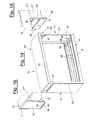
- a piece of metal furniture 10 that can for example be a wardrobe, shelving, a chest of drawers, a filing cabinet or the like, is partially schematised.
- the furniture 10 comprises a pair of sides 11, a base 12 and a top 13 arranged to be assembled through engagement completed through bolting or attachment through screws in already-threaded holes, to realise the substantially quadrangular perimetric structure of the furniture.
- the indicated system for completing the assembly is purely an example, with self-threading screws and rivets being able to be used.
- the fixed assembly can also be completed through a nail, for example made from plastic, suitable for preventing disassembly for example during lifting and movement of the furniture.
- the furniture can, if necessary, be closed through one or more backs and doors (not illustrated), and can be equipped with shelves 18 fixed to uprights 19 in turn fixed to a base plane 20 fixed to the base 12.
- the furniture 10 is equipped, for each corner, with a fixed joint comprising a first or a second shaped element, respectively indicated with 30 or 30', each realised in the form of an elongated element, equipped with a wing 31 projecting from each of its two opposite ends in a direction perpendicular to the shaped element itself so as to realise a U-shaped profile view from the front.
- Such a shaped element is fixed to each end of the base 12 and of the top 13.
- the shaped element can be fixed to each end of each side 11.
- the attachment of the element to the corresponding part of the furniture is realised so that the shaped element has the wings 31 arranged to be inserted in engagement seats 55 realised correspondingly in each end of the sides 11 or alternatively of the base 12 and of the top 13.
- each shaped element 30, 30' shall have its wings 31 inserted in the corresponding engagement seats 55 so as to obtain a substantially stiffer corner in the perimetric structure of the furniture itself, irrespective of the mutual position of the shaped element and the engagement seats.
- the elements carrying the respective joint portions can be arranged in the production step to proceed to assembly still in the production step, or else the parts an be packaged separately leaving such assembly to the user.
- the type of assembly foreseen creates reduced bulk and practically eliminates the need for turning over of the furniture so as to be able to be carried out by a single operator possibly at a site very close to the definitive location of the furniture or of the packaging thereof.
- the first shaped element 30 is previously fixed to the base whereas the second shaped element 30' is fixed to the top.
- the configuration of the two shaped elements 30, 30' is slightly different, the first shaped element 30 being arranged to fixedly house one or more stringers 40 arranged parallel to the longer sides of the base to increase its resistance to loads whereas the second shaped element 30', not having to support such loads, has a lighter configuration, as shall become clearer hereafter.
- the base 12 in the embodiment shown, has a rectangular plan with long sides 14 folded so as to form the ribbing and containment edges 15, and substantially open short sides 16, possibly having a fold 17 of limited height so as to constitute a small rigidifying and containment edge.
- Such short sides 16 are each closed by the first shaped element 30 through attachment thereof to an end of the base, preferably through point welding.
- the first shaped element 30, intended for the base 12 has, on the side, the two wings 31 which extend from a profile 32 folded so as to have, in section, a profile in the shape of two upturned Us joined through a wing in common.
- the wings 31 in turn have an angular shape defined by a first portion 31' arranged substantially adjacent to the end of the edge 15 of the long side of the base 12 and a second portion 31", perpendicular to the first, going out from the wing of the profile 32 and thus arranged along the short side of the base.
- Such a profile 32 therefore, has a band 32' defined by one wing of the double "U”, from each of the two ends of which extends a wing 31, with its second portion 31' coplanar to the strip 32'.
- the profile 32 has transversally, at least one cut 33 formed on the wing opposite the strip 32' and on the adjacent base and suitable for fixedly receiving an end of the corresponding stringer 40.
- the function of the strip 32', as well as structural rigidification of the shaped element, is that of allowing the bolting of a corresponding integral blade (in the example shown) to the side 11 which, with engagement completed, is in contact with said base strip lying over the top of it.
- the top 13 is illustrated, in upturned position, which correspondingly to the base 12, has a rectangular plan with the longer sides 14 folded so as to form ribbing and containment edges 15, and substantially open short sides 16, possibly having a fold 17 of limited height so as to constitute a small rigidifying and containment edge.
- Such short sides 16 are each closed by the second shaped element 30' through attachment thereof to an end of the base, preferably through point welding.
- the second shaped element 30' is realised substantially the same as the first, having, at the side, the two wings 31 which extend from a profile 32a that is lighter than the homologous profile 32 since it has, in section, a profile in the shape of two upturned Us and joined through a wing in common, but without the wing arranged towards the inside of the top, i.e. terminating with a raised base parallel to the plane of the top.
- the second element 30' also has the wings 31 shaped to be angled, with a first portion 31' arranged substantially adjacent to the end of the edge 15 of the longer side of the top 13 and a second portion 31", perpendicular to the first, going out from the wing of the profile 32a and thus arranged along the short side of the top.
- Such a profile 32a thus has a band 32a' defined by a wing of the double U, from each of the two ends of which extends the wing 31, with its second portion 31' coplanar to the strip 32a'.
- Each side 11 of the furniture in the exemplified embodiment, is substantially rectangular shaped defined by longer sides 21 and short sides 22.
- the side is realised through a sheet of plate constituting the side wall 11', folded along both of the longer sides 21 so as to realise a fold 23 for each longer side.
- an engagement element 50 is fixed realised in the form of a U-shaped profile defined by two tabs 51 and 52 and a base 53.
- Such an engagement element 50 is fixed along each short side 22 preferably through welding of one of the two tabs to the wall 11' of the side 11 between the two folds 23 so as to have the opening of the U facing towards the top 13 or the base 12 during assembly.
- the tab 52 intended for attachment to the wall 11' of the side 11 has, for its entire length, an end portion 54 folded towards the inside of the U so as to realise a housing for receiving the folds 17 of the corresponding top or base.
- the realisation of the engagement element 50 is foreseen to obtain, in cooperation with the folds 23 of the long sides 21, a pair of engagement seats 55 suitable for receiving the corresponding wings 31, so as to realise a partial engagement of the sides with the top and the base.
- the tab 51 with assembly carried out, is arranged in contact with the corresponding strip 31' or 31a' so as to be fixed to them, for example through bolting, so as to define the assembly of the furniture structure.
Landscapes
- Assembled Shelves (AREA)
- Furniture Connections (AREA)
Priority Applications (1)
| Application Number | Priority Date | Filing Date | Title |
|---|---|---|---|
| EP04075228A EP1557112A1 (de) | 2004-01-22 | 2004-01-22 | Verbindung für Möbel aus Metall |
Applications Claiming Priority (1)
| Application Number | Priority Date | Filing Date | Title |
|---|---|---|---|
| EP04075228A EP1557112A1 (de) | 2004-01-22 | 2004-01-22 | Verbindung für Möbel aus Metall |
Publications (1)
| Publication Number | Publication Date |
|---|---|
| EP1557112A1 true EP1557112A1 (de) | 2005-07-27 |
Family
ID=34626525
Family Applications (1)
| Application Number | Title | Priority Date | Filing Date |
|---|---|---|---|
| EP04075228A Withdrawn EP1557112A1 (de) | 2004-01-22 | 2004-01-22 | Verbindung für Möbel aus Metall |
Country Status (1)
| Country | Link |
|---|---|
| EP (1) | EP1557112A1 (de) |
Citations (4)
| Publication number | Priority date | Publication date | Assignee | Title |
|---|---|---|---|---|
| US4114336A (en) * | 1975-11-19 | 1978-09-19 | Westinghouse Electric Corp. | Electrical switchboard framework |
| US4274547A (en) * | 1978-12-04 | 1981-06-23 | Tokyo Shibaura Henki Kabushiki Kaisha | Enclosed switchboard |
| GB2193880A (en) * | 1986-06-26 | 1988-02-24 | Twinlock Plc | Improvements in and relating to metal housings |
| US6357610B1 (en) * | 2000-11-03 | 2002-03-19 | Francisco D. Irace | Interlocking cabinet assembly |
-
2004
- 2004-01-22 EP EP04075228A patent/EP1557112A1/de not_active Withdrawn
Patent Citations (4)
| Publication number | Priority date | Publication date | Assignee | Title |
|---|---|---|---|---|
| US4114336A (en) * | 1975-11-19 | 1978-09-19 | Westinghouse Electric Corp. | Electrical switchboard framework |
| US4274547A (en) * | 1978-12-04 | 1981-06-23 | Tokyo Shibaura Henki Kabushiki Kaisha | Enclosed switchboard |
| GB2193880A (en) * | 1986-06-26 | 1988-02-24 | Twinlock Plc | Improvements in and relating to metal housings |
| US6357610B1 (en) * | 2000-11-03 | 2002-03-19 | Francisco D. Irace | Interlocking cabinet assembly |
Similar Documents
| Publication | Publication Date | Title |
|---|---|---|
| CZ282601B6 (cs) | Rámová konstrukce pro skříňový rozvaděč | |
| US4108520A (en) | Drawers | |
| EP0298433A2 (de) | Trennwand, insbesondere für Büros | |
| US7765937B2 (en) | Table system | |
| JPH0514485B2 (de) | ||
| CA1068388A (en) | Electrical switchboard framework | |
| US3432061A (en) | Modular display bin | |
| CA2307423A1 (en) | Cardboard broadsheet for constructing a stackable box and the box resulting therefrom | |
| US5348170A (en) | Free-standing shelving system | |
| EP1847502A1 (de) | Platte für Aufzugtüren | |
| US20050242164A1 (en) | Stacking box for perishable products | |
| EP3036172B1 (de) | Metallpalette mit montierbaren komponenten | |
| EP0399595B1 (de) | Mittels Verbindungsteilen zusammengebauter Schrank für elektrische Installationen | |
| US3981413A (en) | Mailbox door mounting arrangement | |
| KR101124538B1 (ko) | 연결형 선반틀 조립용 연결구 | |
| EP2182128A1 (de) | Aufhängbares Deckeninselsystem | |
| EP2997854B1 (de) | Modulare komponente eines möbelartikels | |
| EP0497741B1 (de) | Aus kastenförmigen Elementen aufgebauter Sockel für Regalmöbel aus Metall | |
| EP1826348A1 (de) | Faltbare Trennwand | |
| JPH07223394A (ja) | ファイリングキャビネット等の引出し | |
| US2608458A (en) | Medicine cabinet | |
| KR200446954Y1 (ko) | 장롱 | |
| US1403961A (en) | Metal shelving | |
| EP4236729B1 (de) | Abdeckung, behälter mit abdeckung und verfahren zur montage einer abdeckung | |
| RU55553U1 (ru) | Шкаф-витрина |
Legal Events
| Date | Code | Title | Description |
|---|---|---|---|
| PUAI | Public reference made under article 153(3) epc to a published international application that has entered the european phase |
Free format text: ORIGINAL CODE: 0009012 |
|
| AK | Designated contracting states |
Kind code of ref document: A1 Designated state(s): AT BE BG CH CY CZ DE DK EE ES FI FR GB GR HU IE IT LI LU MC NL PT RO SE SI SK TR |
|
| AX | Request for extension of the european patent |
Extension state: AL LT LV MK |
|
| AKX | Designation fees paid | ||
| REG | Reference to a national code |
Ref country code: DE Ref legal event code: 8566 |
|
| STAA | Information on the status of an ep patent application or granted ep patent |
Free format text: STATUS: THE APPLICATION IS DEEMED TO BE WITHDRAWN |
|
| 18D | Application deemed to be withdrawn |
Effective date: 20060128 |