EP1557263A1 - Bogenrotationsdruckmaschine - Google Patents
Bogenrotationsdruckmaschine Download PDFInfo
- Publication number
- EP1557263A1 EP1557263A1 EP05000698A EP05000698A EP1557263A1 EP 1557263 A1 EP1557263 A1 EP 1557263A1 EP 05000698 A EP05000698 A EP 05000698A EP 05000698 A EP05000698 A EP 05000698A EP 1557263 A1 EP1557263 A1 EP 1557263A1
- Authority
- EP
- European Patent Office
- Prior art keywords
- cylinder
- throw
- impression cylinder
- plate
- blanket
- Prior art date
- Legal status (The legal status is an assumption and is not a legal conclusion. Google has not performed a legal analysis and makes no representation as to the accuracy of the status listed.)
- Withdrawn
Links
Images




Classifications
-
- B—PERFORMING OPERATIONS; TRANSPORTING
- B41—PRINTING; LINING MACHINES; TYPEWRITERS; STAMPS
- B41F—PRINTING MACHINES OR PRESSES
- B41F7/00—Rotary lithographic machines
- B41F7/02—Rotary lithographic machines for offset printing
- B41F7/04—Rotary lithographic machines for offset printing using printing units incorporating one forme cylinder, one transfer cylinder, and one impression cylinder, e.g. for printing on webs
- B41F7/06—Rotary lithographic machines for offset printing using printing units incorporating one forme cylinder, one transfer cylinder, and one impression cylinder, e.g. for printing on webs for printing on sheets
-
- B—PERFORMING OPERATIONS; TRANSPORTING
- B41—PRINTING; LINING MACHINES; TYPEWRITERS; STAMPS
- B41F—PRINTING MACHINES OR PRESSES
- B41F31/00—Inking arrangements or devices
- B41F31/30—Arrangements for tripping, lifting, adjusting, or removing inking rollers; Supports, bearings, or forks therefor
- B41F31/301—Devices for tripping and adjusting form rollers
-
- B—PERFORMING OPERATIONS; TRANSPORTING
- B41—PRINTING; LINING MACHINES; TYPEWRITERS; STAMPS
- B41P—INDEXING SCHEME RELATING TO PRINTING, LINING MACHINES, TYPEWRITERS, AND TO STAMPS
- B41P2227/00—Mounting or handling printing plates; Forming printing surfaces in situ
- B41P2227/70—Forming the printing surface directly on the form cylinder
Definitions
- the present invention relates to a sheet-fed offset rotary printing press suitable to perform multicolor printing on one paper sheet.
- a conventional sheet-fed offset rotary printing press has two double-size plate cylinders each having two printing surfaces, four inking units for supplying inks to the four printing surfaces of the two plate cylinders, two double-size blanket cylinders which are respectively in contact with the two plate cylinders and each of which has two printing surfaces, one triple-size impression cylinder with which the two blanket cylinders are in contact and which has three gripper devices to grip paper sheets, and two laser inscribing systems which respectively form images on the two plate cylinders.
- a sheet-fed offset rotary printing press comprising one plate cylinder having an outer surface on which at least one plate member is mounted, one blanket cylinder which opposes the plate cylinder and has an outer surface on which at least one blanket is mounted, the blanket cylinder having the same size as that of the plate cylinder, one impression cylinder having at least one sheet holding means for holding a sheet (or a sheet type object), one plate making device which can inscribe four printing patterns on four regions of the plate member while the plate member is mounted on the plate cylinder, four inking devices which individually supply inks to the four printing patterns of the plate member mounted on the plate cylinder through four form rollers, four roller throw-on/throw-off devices which throw on one of the four form rollers onto a corresponding one of the four printing patterns of the plate member mounted on the plate cylinder and throw off the remaining ones of the form rollers from the remaining ones of the printing patterns, and a cylinder throw-on/throw-off device which throws on the
- a sheet-fed offset rotary printing press 1 includes a feeder 4 which feeds paper sheet 2 stacked on a pile board 8 onto a feeder board 3 one by one, a printing unit 5 which prints the fed paper sheet 2, a delivery unit 6 which conveys the printed paper sheet 2 and delivers it onto a pile board 9 to stack it there, and a plate making device 7 which plate-makes a plate mounted on the outer surface of a plate cylinder 11 that forms the printing unit 5.
- the paper sheet 2 fed onto the feeder board 3 is positioned by a registration device (not shown) and gripped by the grippers of a swing arm shaft gripper 10.
- the paper sheet 2 is conveyed to the outer surface of an impression cylinder 13 that forms the printing unit 5, and gripping-changed to gripper devices 36A to 36C of the impression cylinder 13 by a gripper opening/closing device 60 (to be described later).
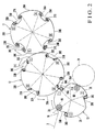
- the printing unit 5 has the plate cylinder 11 with an outer surface on which printing plates 28A to 28D (Fig. 2) are mounted, a blanket cylinder 12 which is in contact with the plate cylinder 11 during printing operation and has an outer surface on which blankets 33A to 33D (Fig. 2) are mounted, the impression cylinder 13 onto/from which the blanket cylinder 12 is thrown on/off during the printing operation by a cylinder throw-on/throw-off device 39 (to be described later), and a pair of frames 14 which support the three cylinders 11, 12, and 13 and oppose each other at a predetermined gap.
- the two end shafts of each of the plate cylinder 11 and impression cylinder 13 are rotatably, axially supported by the pair of frames 14 through bearings (not shown).
- the two end shafts of the blanket cylinder 12 are rotatably, axially supported by eccentric bearings 41 (to be described later) fitted on the pair of frames 14.
- Each of the inking devices 15A to 15D includes an ink fountain 16, an anilox roller 17 which extracts the ink from the ink fountain 16, and an ink form roller 18 which is in contact with the anilox roller 17 and brought into selective contact with the outer surface of the plate cylinder 11 by a roller throw-on/throw-off device 54 (to be described later) to supply the ink to the plate (28A to 28D) mounted on the outer surface of the plate cylinder 11.
- a dampener 19 supplies dampening water to the outer surface of the plate cylinder 11.
- the delivery unit 6 has a take-off cylinder 21 in contact with the impression cylinder 13, a pair of front sprockets 22 which line up to be coaxial with the take-off cylinder 21, a pair of rear sprockets 23 rotatably supported at the rear portions of the frames 14 to oppose each other, and a pair of delivery chains 24 looped between the sprockets 22 and 23.
- Each of the pair of delivery chains 24 has two delivery grippers 24a at a predetermined distance 1' in its traveling direction. The distance between the delivery grippers 24a is set to correspond to a circumferential length 1" of one revolution of the plate cylinder 11.
- paper sheet gripping change is performed, at the contact portion of the impression cylinder 13 and take-off cylinder 21, between an odd number of the gripper devices 36A to 36C of the impression cylinder 13 and the delivery grippers 24a of the delivery chains 24 by the gripper opening/closing device 60 (to be described later). Subsequently, the delivery chains 24 travel to convey the paper sheet backward, and the paper sheet is released from the delivery grippers 24a so that it is delivered and stacked on the pile board 9.
- the plate cylinder 11 has a quadruple size.
- Four notches 25A to 25D are formed in the outer surface of the plate cylinder 11 at positions equiangularly phase-shifted from each other in the circumferential direction, so as to extend in the entire portion of the outer surface in the axial direction.
- Each of leading edge holding mechanisms 26A to 26D for holding the leading edge of the plate and each of trailing edge holding mechanisms 27A to 27D for holding the trailing edge of the plate are arranged respectively at the two ends of the corresponding one of the notches 25A to 25D.
- the four plates 28A to 28D are mounted between the leading edge holding mechanisms 26A to 26D and trailing edge holding mechanisms 27A to 27D of the notches 25A to 25D such that each plate covers an outer surface portion between the leading edge holding mechanism of one notch and the trailing edge holding mechanism of the adjacent notch. More specifically, the plate cylinder 11 has four printing surfaces 28A to 28D equidistantly in the circumferential direction. The regions of the four printing surfaces 28A to 28D will be referred to as phases "A", "B", “C”, and “D" of the plate cylinder 11 hereinafter.
- the blanket cylinder 12 has a quadruple size.
- Four notches 30A to 30D are formed in the outer surface of the blanket cylinder 12 at positions equiangularly phase-shifted from each other in the circumferential direction, so as to extend in the entire portion of the outer surface in the axial direction.
- Each of leading edge holding mechanisms 31A to 31D for holding the leading edge of the plate and each of trailing edge holding mechanisms 32A to 32D for holding the trailing edge of the plate are arranged respectively at the two ends of the corresponding one of the notches 30A to 30D.
- the four blankets 33A to 33D are mounted between the leading edge holding mechanisms 31A to 31D and trailing edge holding mechanisms 32A to 32D of adjacent ones of the notches 30A to 30D such that each blanket covers an outer surface portion between the leading edge holding mechanism of one notch and the trailing edge holding mechanism of the adjacent notch.
- the phase of the blanket cylinder 12 with respect to the plate cylinder 11 is set such that the four notches 30A to 30D oppose the corresponding ones of the four notches 25A to 25D of the plate cylinder 11.
- the four printing surfaces 28A to 28D of the plate cylinder 11 respectively come into contact with the four blankets 33A to 33D of the blanket cylinder 12.
- the four blankets 33A to 33D of the blanket cylinder 12 serve as the four printing surfaces 33A to 33D formed equidistantly in the circumferential direction.
- the regions of the four printing surfaces 33A to 33D will be referred to as phases "A", "B", “C”, and "D" of the blanket cylinder 12 hereinafter.
- the impression cylinder 13 has a triple size.
- Three notches 35A to 35C are formed in the outer surface of the impression cylinder 13 at positions equiangularly phase-shifted from each other in the circumferential direction, so as to extend in the entire portion of the outer surface in the axial direction.
- the gripper devices 36A to 36C for gripping the leading edge of the paper sheet are arranged, each at one end of the corresponding one of the notches 35A to 35C, equidistantly in the circumferential direction.
- the phase of the impression cylinder 13 with respect to the blanket cylinder 12 is set such that the three notches 35A to 35C oppose either ones of the four notches 30A to 30D of the blanket cylinder 12.
- each of paper sheets 2A to 2C respectively gripped by the gripper devices 36A to 36C of the impression cylinder 13 is printed by either one of the printing surfaces 33A to 33D of the blanket cylinder 12 at the contact portion of the impression cylinder 13 and blanket cylinder 12.
- the regions of the paper sheets 2A to 2C gripped by the gripper devices 36A to 36C of the impression cylinder 13 will be referred to as phases "1", “2", and "3" of the impression cylinder 13 hereinafter.
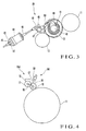
- the cylinder throw-on/throw-off device 39 which throws on/off the plate cylinder 11 and impression cylinder 13 will be described with reference to Fig. 3.
- two end shafts 40 of the blanket cylinder 12 are rotatably supported by the two eccentric bearings 41 fitted on the pair of frames 14.
- a bracket 43 is supported by a stud 42 projecting outside one frame 14, and a stepping motor 44 is fixed to the bracket 43.
- a driving rod 46 threadably engaging with the threaded portion of the nut 45 moves forward/backward.
- the central portion of an L-shaped connecting lever 48 is axially mounted on a lever shaft 47 rotatably axially supported by the frame 14.
- the distal end of the driving rod 46 is pivotally mounted on one end of the connecting lever 48.
- a driving lever 49 fixed to the outer ring of one eccentric bearing 41 and the other end of the connecting lever 48 are connected to each other through a rod 50.
- the connecting lever 48 pivots counterclockwise about the lever shaft 47 as the center as indicated by a solid line in Fig. 3, so that the eccentric bearing 41 pivots through the rod 50 and driving lever 49.
- the blanket cylinder 12 comes into contact with the plate cylinder 11 and impression cylinder 13.
- the connecting lever 48 pivots to a position between the position indicated by a solid line and the position indicated by an alternate long and two short dashed line, to realize a so-called blanket cylinder-impression cylinder throw-off (to be referred to as B-I throw-off) state wherein the blanket cylinder 12 while kept in contact with the plate cylinder 11 is separated from the impression cylinder 13.
- B-I throw-off blanket cylinder-impression cylinder throw-off
- the connecting lever 48 pivots to the position indicated by the alternate long and two short dashed line, and the blanket cylinder 12 separates from the plate cylinder 11 as well, thus performing impression throw-off.
- the ink form roller throw-on/throw-off devices 54 will be described with reference to Fig. 4.
- the ink form roller throw-on/throw-off devices 54 are provided to the four inking devices 15A to 15D, respectively, and have the same structure.
- the ink form roller throw-on/throw-off device 54 provided to the inking device 15A will be described hereinafter, and a description on the remaining inking devices 15B to 15D will be omitted.
- An arm 55 has one end pivotally supported by the central portion of the anilox roller 17. The other end of the arm 55 is attached to the central portion of the ink form roller 18.
- a throw-on/throw-off pneumatic cylinder 56 has a cylinder end pivotally supported by the frame 14. The distal end of a rod 57 of the pneumatic cylinder 56 is pivotally mounted on the arm 55. In this structure, when the pneumatic cylinder 56 is actuated to move the rod 57 forward, the ink form roller 18 comes into contact with the outer surface of the plate cylinder 11. When the rod 57 moves backward, the ink form roller 18 separates from the outer surface of the plate cylinder 11.
- each of the gripper devices 36A to 36C has a plurality of grippers 62 axially mounted on a gripper shaft 61 at substantially predetermined intervals and a gripper pad 63 which grips the leading edge of the paper sheet together with the grippers 62.
- the gripper opening/closing device 60 is attached to the frames 14 in relation to a gripping change position 65, with respect to the swing arm shaft gripper 10, surrounded by an alternate long and two short dashed line and indicated by hatched grids in Fig. 2.
- the gripper opening/closing device 160 is attached to the frames 14 in relation to a gripping change position 66, with respect to the delivery grippers 24a of the delivery chains 24, which is surrounded by an alternate long and two short dashed line and indicated by hatched grids in Fig. 2.
- the gripper opening/closing devices 60 and 160 respectively have pneumatic cylinders 67 and 167 and cams 70 and 170.
- the cylinder ends of the pneumatic cylinders 67 and 167 are respectively pivotally supported by the frames 14.
- a rod 68 of the pneumatic cylinder 67 is pivotally mounted on one end of the cam 70.
- the other end of the cam 70 is pivotally supported by the frames 14 through a pin 69.
- a rod 168 of the pneumatic cylinder 167 is pivotally mounted on one end of the cam 170.
- the other end of the cam 170 is pivotally supported by the frames 14 through a pin 169.
- four plates 28A to 28D which are not plate-made yet are mounted on the plate cylinder 11, and are plate-made by the plate making device 7.
- Four different-color inks are respectively supplied to the plate-made plates 28A to 28D by the four inking devices 15A to 15D. More specifically, black ink is supplied to the plate 28A by the ink form roller 18 of the inking device 15A. Yellow ink is supplied to the plate 28B by the ink form roller 18 of the inking device 15B. Red ink is supplied to the plate 28C by the ink form roller 18 of the inking device 15C. Blue ink is supplied to the plate 28D by the ink form roller 18 of the inking device 15D.
- the inks of the four different colors supplied to the plates 28A to 28D are transferred to the blankets 33A to 33D, with which the plates 28A to 28D respectively come into contact, of the blanket cylinder 12 as black, yellow, red, and blue patterns.
- the rod 68 of the pneumatic cylinder 67 moves backward, and the large-diameter portion 70a of the cam 70 is positioned at the retreat position.
- the gripper device 36A opposes the leading edge holding mechanism 31A of the blanket cylinder 12.
- the blanket cylinder 12 is brought into contact with the impression cylinder 13 by the cylinder throw-on/throw-off device 39.
- the impression cylinder 13 further pivots to bring the phase "A" of the blanket cylinder 12 and the phase "1" of the impression cylinder 13 into contact with each other.
- a black pattern is printed on the first paper sheet, as shown in Figs. 8A and 8B.
- the blanket cylinder 12 is separated from the impression cylinder 13 by the cylinder throw-on/throw-off device 39 to perform B - I throw-off.
- the B - I throw-off is held while the impression cylinder 13 and blanket cylinder 12 rotate by 2/3 revolution and 2/4 revolution, respectively, until immediately before the phase "1" of the impression cylinder 13 comes into contact with the phase "D" of the blanket cylinder 12.
- set-off on cylinder does not occur on the outer surface of the impression cylinder 13.
- the B - I throw-off is canceled by the cylinder throw-on/throw-off device 39.
- the blanket cylinder 12 comes into contact with the impression cylinder 13, and a blue pattern is printed on the first paper sheet.
- a paper sheet 2 is fed by the feeder 4 onto the feeder board 3, it is positioned by the register device (not shown) and gripped by the grippers of the swing arm shaft gripper 10, and conveyed to the outer surface of the impression cylinder 13.
- the rod 68 of the pneumatic cylinder 67 which forms the gripper opening/closing device 60 moves forward.
- the large-diameter portion 70a of the cam 70 of the pneumatic cylinder 67 is positioned at the operative position, and the leading edge of the paper sheet 2 is gripping-changed to the gripper device 36B of the impression cylinder 13.
- the rod 68 of the pneumatic cylinder 67 of the gripper opening/closing device 60 moves backward, and the large-diameter portion 70a of the cam 70 is positioned at the retreat position.
- the impression cylinder 13 and blanket cylinder 12 rotate to bring the phase "2" of the impression cylinder 13 and the phase "A” of the blanket cylinder 12 into contact with each other.
- a black pattern is printed on the second paper sheet.
- the impression cylinder 13 and blanket cylinder 12 further rotate by 1/3 revolution and 1/4 revolution, respectively.
- the blanket cylinder 12 is separated from the impression cylinder 13 by the cylinder throw-on/throw-off device 39 to perform B - I throw-off.
- the blanket cylinder 12 does not come into contact with the phase "3" of the impression cylinder 13 which does not grip a paper sheet, set-off on cylinder does not occur on the outer surface of the impression cylinder 13.
- the impression cylinder 13 and blanket cylinder 12 further rotate. Immediately before the phase “1" of the impression cylinder 13 comes into contact with the phase "C" of the blanket cylinder 12, the B - I throw-off is canceled by the cylinder throw-on/throw-off device 39. The blanket cylinder 12 comes into contact with the impression cylinder 13, and a red pattern is printed on the first paper sheet.
- the impression cylinder 13 and blanket cylinder 12 further rotate by 1/3 revolution and 1/4 revolution, respectively, to bring the phase "2" of the impression cylinder 13 into contact with the phase "D" of the blanket cylinder 12.
- a blue pattern is printed on the second paper sheet.
- the rod 68 of the pneumatic cylinder 67 of the gripper opening/closing device 160 moves backward, and the large-diameter portion 70a of the cam 70 is positioned at the retreat position.
- the impression cylinder 13 and blanket cylinder 12 rotate to bring the phase "3" of the impression cylinder 13 and the phase "A” of the blanket cylinder 12 into contact with each other.
- a black pattern is printed on the third paper sheet.
- the impression cylinder 13 and blanket cylinder 12 further rotate by 1/3 revolution and 1/4 revolution, respectively, to bring the phase "1" of the impression cylinder 13 into contact with the phase "B" of the blanket cylinder 12.
- a yellow pattern is printed on the first paper sheet.
- the rod 168 of the pneumatic cylinder 167 of the gripper opening/closing device 160 moves forward, and the large-diameter portion 170a of the cam 170 is positioned at the operative position.
- the gripper device 36A of the impression cylinder 13 opposes the delivery grippers 24a of the delivery chains 24, the first paper sheet on which the four different-color patterns are printed is gripping-changed, and the leading edge of the paper sheet is gripped by the delivery grippers 24a.
- the paper sheet gripped by the delivery grippers 24a is conveyed as the delivery chains 24 travel, and delivered as it is released above the pile board 9 of the delivery unit 6.
- the first paper sheet is thus stacked on the pile board 9.
- the rod 168 of the pneumatic cylinder 167 of the gripper opening/closing device 160 moves backward, and the large-diameter portion 170a of the cam 170 is positioned at the retreat position.
- the impression cylinder 13 and blanket cylinder 12 further rotate by 1/3 revolution and 1/4 revolution, respectively, to bring the phase "2" of the impression cylinder 13 into contact with the phase "C” of the blanket cylinder 12.
- a red pattern is printed on the second paper sheet.
- the impression cylinder 13 and blanket cylinder 12 further rotate by 1/3 revolution and 1/4 revolution, respectively, to bring the phase "3" of the impression cylinder 13 into contact with the phase "D" of the blanket cylinder 12.
- a blue pattern is printed on the third paper sheet.
- the rod 68 of the pneumatic cylinder 67 of the gripper opening/closing device 60 moves backward, and the large-diameter portion 70a of the cam 70 is positioned at the retreat position.
- the impression cylinder 13 and blanket cylinder 12 rotate to bring the phase "1" of the impression cylinder 13 and the phase "A” of the blanket cylinder 12 into contact with each other.
- a black pattern is printed on the fourth paper sheet.
- the impression cylinder 13 and blanket cylinder 12 further rotate by 1/3 revolution and 1/4 revolution, respectively, to bring the phase "2" of the impression cylinder 13 into contact with the phase "B" of the blanket cylinder 12.
- a yellow pattern is printed on the second paper sheet.
- the rod 168 of the pneumatic cylinder 167 moves forward, and the large-diameter portion 170a of the cam 170 is positioned at the operative position.
- the gripper device 36B of the impression cylinder 13 opposes the delivery grippers 24a of the delivery chains 24, the second paper sheet on which the four different-color patterns are printed is gripping-changed, and the leading edge of the paper sheet is gripped by the delivery grippers 24a.
- the paper sheet gripped by the delivery grippers 24a is conveyed as the delivery chains 24 travel, and delivered as it is released above the pile board 9 of the delivery unit 6.
- the second paper sheet is thus stacked on the pile board 9.
- the rod 168 of the pneumatic cylinder 167 moves backward, and the large-diameter portion 170a of the cam 170 is positioned at the retreat position.
- the impression cylinder 13 and blanket cylinder 12 further rotate by 1/3 revolution and 1/4 revolution, respectively, to bring the phase "3" of the impression cylinder 13 into contact with the phase "C” of the blanket cylinder 12.
- a red pattern is printed on the third paper sheet.
- the impression cylinder 13 and blanket cylinder 12 further rotate by 1/3 revolution and 1/4 revolution, respectively, to bring the phase "1" of the impression cylinder 13 into contact with the phase "D" of the blanket cylinder 12.
- a blue pattern is printed on the fourth paper sheet.
- the rod 68 of the pneumatic cylinder 67 moves backward, and the large-diameter portion 70a of the cam 70 is positioned at the retreat position.
- the impression cylinder 13 and blanket cylinder 12 rotate to bring the phase "2" of the impression cylinder 13 and the phase "A" of the blanket cylinder 12 into contact with each other, as shown in Fig. 6A.
- a black pattern is printed on the fifth paper sheet.
- the impression cylinder 13 and blanket cylinder 12 further rotate by 1/3 revolution and 1/4 revolution, respectively, to bring the phase "3" of the impression cylinder 13 into contact with the phase "B" of the blanket cylinder 12.
- a yellow pattern is printed on the third paper sheet.
- the rod 168 of the pneumatic cylinder 167 moves forward, and the large-diameter portion 170a of the cam 170 is positioned at the operative position.
- the gripper device 36C of the impression cylinder 13 opposes the delivery grippers 24a of the delivery chains 24, the third paper sheet on which the four different-color patterns are printed is gripping-changed, and the leading edge of the paper sheet is gripped by the delivery grippers 24a.
- the paper sheet gripped by the delivery grippers 24a is conveyed as the delivery chains 24 travel, and delivered as it is released above the pile board 9 of the delivery unit 6.
- the third paper sheet is thus delivered and stacked on the pile board 9.
- the rod 168 of the pneumatic cylinder 167 moves backward, and the large-diameter portion 170a of the cam 170 is positioned at the retreat position.
- the impression cylinder 13 and blanket cylinder 12 further rotate by 1/3 revolution and 1/4 revolution, respectively, to bring the phase "1" of the impression cylinder 13 into contact with the phase "C" of the blanket cylinder 12.
- a red pattern is printed on the fourth paper sheet.
- the impression cylinder 13 and blanket cylinder 12 further rotate by 1/3 revolution and 1/4 revolution, respectively, to bring the phase "2" of the impression cylinder 13 into contact with the phase "D" of the blanket cylinder 12.
- a blue pattern is printed on the fifth paper sheet.
- the rod 68 of the pneumatic cylinder 67 moves backward, and the large-diameter portion 70a of the cam 70 is positioned at the retreat position.
- the impression cylinder 13 and blanket cylinder 12 rotate to bring the phase "3" of the impression cylinder 13 and the phase "A” of the blanket cylinder 12 into contact with each other.
- a black pattern is printed on the sixth paper sheet.
- the impression cylinder 13 and blanket cylinder 12 further rotate by 1/3 revolution and 1/4 revolution, respectively, to bring the phase "1" of the impression cylinder 13 into contact with the phase "B" of the blanket cylinder 12.
- a yellow pattern is printed on the fourth paper sheet.
- the rod 168 of the pneumatic cylinder 167 moves forward, and the large-diameter portion 170a of the cam 170 is positioned at the operative position.
- the fourth paper sheet on which the four different-color patterns are printed is gripping-changed, and the leading edge of the paper sheet is gripped by the delivery grippers 24a.
- the paper sheet gripped by the delivery grippers 24a is conveyed as the delivery chains 24 travel, and is released above the pile board 9 of the delivery unit 6.
- the fourth paper sheet is thus delivered and stacked on the pile board 9.
- the impression cylinder 13 and blanket cylinder 12 further rotate by 1/3 revolution and 1/4 revolution, respectively, to bring the phase "2" of the impression cylinder 13 into contact with the phase "C” of the blanket cylinder 12.
- a red pattern is printed on the fifth paper sheet.
- the impression cylinder 13 and blanket cylinder 12 further rotate by 1/3 revolution and 1/4 revolution, respectively, to bring the phase "3" of the impression cylinder 13 into contact with the phase "D" of the blanket cylinder 12.
- a blue pattern is printed on the sixth paper sheet.
- the impression cylinder 13 and blanket cylinder 12 further rotate by 1/3 revolution and 1/4 revolution, respectively.
- the blanket cylinder 12 is separated from the impression cylinder 13 by the cylinder throw-on/throw-off device 39 to perform B - I throw-off.
- the blanket cylinder 12 does not come into contact with the phase "1" of the impression cylinder 13 which does not grip a paper sheet, set-off on cylinder does not occur on the outer surface of the impression cylinder 13.
- the impression cylinder 13 and blanket cylinder 12 further rotate by 1/3 revolution and 1/4 revolution, respectively, to bring the phase "2" of the impression cylinder 13 into contact with the phase "B" of the blanket cylinder 12.
- a yellow pattern is printed on the fifth paper sheet.
- the rod 168 of the pneumatic cylinder 167 moves forward, and the large-diameter portion 170a of the cam 170 is positioned at the operative position.
- the gripper device 36B of the impression cylinder 13 opposes the delivery grippers 24a of the delivery chains 24, the fifth paper sheet on which the four different-color patterns are printed is gripping-changed, and the leading edge of the paper sheet is gripped by the delivery grippers 24a.
- the paper sheet gripped by the delivery grippers 24a is conveyed as the delivery chains 24 travel, and delivered as it is released above the pile board 9 of the delivery unit 6.
- the fifth paper sheet is thus stacked on the pile board 9.
- the rod 168 of the pneumatic cylinder 167 moves backward, and the large-diameter portion 170a of the cam 170 is positioned at the retreat position.
- the impression cylinder 13 and blanket cylinder 12 further rotate by 1/3 revolution and 1/4 revolution, respectively, to bring the phase "3" of the impression cylinder 13 into contact with the phase "C” of the blanket cylinder 12.
- a red pattern is printed on the sixth paper sheet.
- the impression cylinder 13 and blanket cylinder 12 further rotate by 1/3 revolution and 1/4 revolution, respectively.
- the blanket cylinder 12 is separated from the impression cylinder 13 by the cylinder throw-on/throw-off device 39 to perform B - I throw-off.
- the blanket cylinder 12 does not come into contact with the phase "1" of the impression cylinder 13 which does not grip a paper sheet, set-off on cylinder does not occur on the outer surface of the impression cylinder 13.
- the B - I throw-off is held until the impression cylinder 13 and blanket cylinder 12 rotate by 2/3 revolution and 2/4 revolution, respectively. As the phase “2" of the impression cylinder 13 does not come into contact with the phase "A" of the blanket cylinder 12, set-off on cylinder does not occur on the outer surface of the impression cylinder 13.
- the impression cylinder 13 and blanket cylinder 12 further rotate. Immediately before the phase "3" of the impression cylinder 13 comes into contact with the phase "B" of the blanket cylinder 12, the B - I throw-off is canceled by the cylinder throw-on/throw-off device 39. The blanket cylinder 12 comes into contact with the impression cylinder 13, and a yellow pattern is printed on the sixth paper sheet. At this time, the rod 168 of the pneumatic cylinder 167 moves forward, and the large-diameter portion 170a of the cam 170 is positioned at the operative position.
- the gripper device 36C of the impression cylinder 13 opposes the delivery grippers 24a of the delivery chains 24, the sixth paper sheet on which the four different-color patterns are printed is gripping-changed, and the leading edge of the paper sheet is gripped by the delivery grippers 24a.
- the paper sheet gripped by the delivery grippers 24a is conveyed as the delivery chains 24 travel, and delivered as it is released above the pile board 9 of the delivery unit 6.
- the sixth paper sheet is thus stacked on the pile board 9.
- the rod 168 of the pneumatic cylinder 167 moves backward, and the large-diameter portion 170a of the cam 170 is positioned at the retreat position.
- the impression cylinder 13 and blanket cylinder 12 further rotate by 1/3 revolution and 1/4 revolution, respectively.
- the blanket cylinder 12 is separated from the impression cylinder 13 and plate cylinder 11 by the cylinder throw-on/throw-off device 39, to perform impression throw-off.
- This impression throw-off operation is held while the impression cylinder 13 rotates by one revolution.
- the printing is ended. In the printing operation described as well, a paper sheet is supplied to the impression cylinder 13 by the swing arm shaft gripper 10 each time the plate cylinder 11 rotates by one revolution.
- the throw-on/throw-off devices 39 of the ink form rollers 18 are actuated in advance.
- the ink form rollers 18 of the four inking devices 15A are separated and disengaged from the plate cylinder 11.
- the blanket cylinder 12 is separated from the impression cylinder 13 to perform B - I throw-off, and separated from the plate cylinder 11 to perform impression throw-off.
- Fig. 1 In this state, in Fig.
- the plate making device 7 is then moved from one end to the other end of the plate cylinder 11 in the axial direction. Subsequently, the plate cylinder 11 is pivoted slightly, and the plate making device 7 is moved from the other end to one end of the plate cylinder 11 in the axial direction. After that, the plate making device 7 is repeatedly reciprocated in the axial direction of the plate cylinder 11. When the plate cylinder 11 rotates by 1/4 revolution, the plate 28A is plate-made. The same operation is repeated three times for the remaining plates 28B to 28D, so that the plates 28B to 28D are plate-made sequentially.
- the four plates 28A to 28D on one plate cylinder 11 are plate-made by one plate making device 7. Therefore, the patterns inscribed on the plates 28A to 28D do not misregister from each other. As will be described later, when multicolor printing is to be performed on the paper sheet 2, color misregistration does not occur, and the printing quality is improved. Since adjustment for preventing color misregistration is not necessary, the productivity is improved. As one plate making device 7 suffices, the manufacturing cost of the printing press can be decreased.
- Black, yellow, red, and blue inks are respectively supplied to the ink fountains 16 of the four inking devices 15A to 15D.
- the blanket cylinder 12 is driven by the cylinder throw-on/throw-off device 39 to come into contact with the plate cylinder 11.
- the plate cylinder 11 rotates clockwise as shown in Fig. 1.
- the leading edge holding mechanism 26A which holds the leading edge of the plate 28A opposes the ink form roller 18 of the inking device 15A
- the ink form roller 18 is brought into contact with the plate cylinder 11 by the ink form roller throw-on/throw-off device 54 of the inking device 15A.
- the ink form roller 18 is brought into contact with the plate cylinder 11 by the ink form roller throw-on/throw-off device 54 of the inking device 15B.
- the trailing edge holding mechanism 27B which holds the trailing edge of the plate 28B opposes the ink form roller 18 of the inking device 15B
- the ink form roller 18 is separated and thrown off from the plate cylinder 11 by the ink form roller throw-on/throw-off device 54 of the inking device 15B.
- the yellow ink is supplied to the plate 28B by the ink form roller 18 of the inking device 15B.
- the red ink is supplied to the plate 28C by the ink form roller 18 of the inking device 15C
- the blue ink is supplied to the plate 28D by the ink form roller 18 of the inking device 15D.
- the four different-color inks respectively supplied to the plates 28A to 28D are transferred as a black pattern, yellow pattern, red pattern, and blue pattern to the blankets 33A to 33D, with which the plates 28A and 28D respectively come into contact, of the blanket cylinder 12.
- the rod 68 of the pneumatic cylinder 67 moves backward, and the large-diameter portion 70a of the cam 70 is positioned at the retreat position.
- the gripper device 36A opposes the leading edge holding mechanism 31A of the blanket cylinder 12, and the blanket cylinder 12 is brought into contact with the impression cylinder 13 by the cylinder throw-on/throw-off device 39.
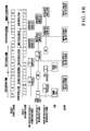
- the impression cylinder 13 further pivots to bring the phase "A" of the blanket cylinder 12 and the phase "1" of the impression cylinder 13 into contact with each other, a black pattern is printed on the first paper sheet, as shown in Figs. 6A and 6B.
- the blanket cylinder 12 is separated from the impression cylinder 13 by the cylinder throw-on/throw-off device 39 to perform B - I throw-off.
- the B - I throw-off is held while the impression cylinder 13 and blanket cylinder 12 rotate by 2/3 revolution and 2/4 revolution, respectively, until immediately before the phase "1" of the impression cylinder 13 comes into contact with the phase "D" of the blanket cylinder 12.
- the blanket cylinder 12 does not come into contact with the phase "2" nor "3" of the impression cylinder 13 which does not grip a paper sheet, set-off on cylinder does not occur on the outer surface of the impression cylinder 13.
- the impression cylinder 13 and blanket cylinder 12 further rotate. Immediately before the phase "2" of the impression cylinder 13 comes into contact with the phase "A" of the blanket cylinder 12, the blanket cylinder 12 is separated from the impression cylinder 13 by the cylinder throw-on/throw-off device 39 to perform B - I throw-off. The impression cylinder 13 and blanket cylinder 12 further rotate by 2/3 revolution and 2/4 revolution, respectively, to bring the phase "1" of the impression cylinder 13 into contact with the phase "C" of the blanket cylinder 12. The B - I throw-off is canceled by the cylinder throw-on/throw-off device 39. The blanket cylinder 12 comes into contact with the impression cylinder 13, and a red pattern is printed on the first paper sheet.
- the impression cylinder 13 and blanket cylinder 12 further rotate. Immediately before the phase "2" of the impression cylinder 13 and the phase “D" of the blanket cylinder 12 come into contact with each other, the blanket cylinder 12 is separated from the impression cylinder 13 by the cylinder throw-on/throw-off device 39 to perform B - I throw-off. The B - I throw-off is held while the impression cylinder 13 and blanket cylinder 12 rotate by 2/3 revolution and 2/4 revolution, respectively, until the phase "1" of the impression cylinder 13 comes into contact with the phase "B" of the blanket cylinder 12.
- the gripper device 36A of the impression cylinder 13 opposes the delivery grippers 24a of the delivery chains 24, the first paper sheet on which the four different-color patterns are printed is gripping-changed, and the leading edge of the paper sheet is gripped by the delivery grippers 24a.
- the blanket cylinder 12 is separated from the impression cylinder 13 and plate cylinder 11 by the cylinder throw-on/throw-off device 39, to perform impression throw-off.
- the paper sheet gripped by the delivery grippers 24a is conveyed as the delivery chains 24 travel, and delivered as it is released above the pile board 9 of the delivery unit 6. The paper sheet is thus stacked on the pile board 9.
- multicolor printing is performed on one paper sheet gripped by the gripper device of one impression cylinder 13.
- Conventional gripper change of the paper sheet between impression cylinders is eliminated.
- Color misregistration in multicolor printing is solved, and the printing quality is improved.
- the paper sheet is supplied to the impression cylinder 13 by the swing arm shaft gripper 10 each time the plate cylinder 11 rotates by one revolution.
- the rod 68 of the pneumatic cylinder 67 moves backward, and the large-diameter portion 70a of the cam 70 is positioned at the retreat position.
- the gripper device 36A opposes the leading edge holding mechanism 31A of the blanket cylinder 12.
- the blanket cylinder 12 is brought into contact with the impression cylinder 13 by the cylinder throw-on/throw-off device 39.
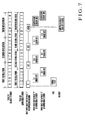
- the impression cylinder 13 further pivots to bring the phase "A" of the blanket cylinder 12 and the phase "1" of the impression cylinder 13 into contact with each other, a black pattern is printed on the first paper sheet, as shown in Figs. 7A and 7B.
- the blanket cylinder 12 is separated from the impression cylinder 13 by the cylinder throw-on/throw-off device 39 to perform B - I throw-off.
- the B - I throw-off is held while the impression cylinder 13 and blanket cylinder 12 rotate by 2/3 revolution and 2/4 revolution, respectively, until immediately before the phase "1" of the impression cylinder 13 comes into contact with the phase "D" of the blanket cylinder 12. Accordingly, the blanket cylinder 12 does not come into contact with the phase "2" nor "3" of the impression cylinder 13 which does not grip a paper sheet.
- a second paper sheet 2 is fed onto the feeder board 3 by the feeder 4, it is positioned by the register device (not shown) and gripped by the grippers of the swing arm shaft gripper 10, and conveyed to the outer surface of the impression cylinder 13.
- the rod 68 of the pneumatic cylinder 67 of the gripper opening/closing device 60 moves forward.
- the large-diameter portion 70a of the cam 70 is positioned at the operative position, and the leading edge of the paper sheet 2 is gripping-changed to the gripper device 36B of the impression cylinder 13.
- the rod 68 of the pneumatic cylinder 67 moves backward, and the large-diameter portion 70a of the cam 70 is positioned at the retreat position.
- the impression cylinder 13 and blanket cylinder 12 rotate to bring the phase "2" of the impression cylinder 13 and the phase "A” of the blanket cylinder 12 into contact with each other, a black pattern is printed on the second paper sheet.
- the impression cylinder 13 and blanket cylinder 12 further rotate by 1/3 revolution and 1/4 revolution, respectively.
- the blanket cylinder 12 is separated from the impression cylinder 13 by the cylinder throw-on/throw-off device 39 to perform B - I throw-off. Therefore, the blanket cylinder 12 does not come into contact with the phase "3" of the impression cylinder 13 which does not grip a paper sheet.
- the B - I throw-off is held while the impression cylinder 13 and blanket cylinder 12 rotate by 2/3 revolution and 2/4 revolution, respectively.
- the phase "1" of the impression cylinder 13 does not come into contact with the phase "C” of the blanket cylinder 12.
- the impression cylinder 13 and blanket cylinder 12 further rotate.
- the B - I throw-off is canceled by the cylinder throw-on/throw-off device 39 to bring the blanket cylinder 12 into contact with the impression cylinder 13.
- a blue pattern is printed on the second paper sheet.
- a third paper sheet 2 is fed onto the feeder board 3 by the feeder 4, it is positioned by the register device (not shown) and gripped by the grippers of the swing arm shaft gripper 10, and conveyed to the outer surface of the impression cylinder 13.
- the rod 68 of the pneumatic cylinder 67 which forms the gripper opening/closing device 60 moves forward.
- the large-diameter portion 70a of the cam 70 is positioned at the operative position, and the leading edge of the paper sheet 2 is gripping-changed to the gripper device 36C of the impression cylinder 13.
- the rod 68 of the pneumatic cylinder 67 moves backward, and the large-diameter portion 70a of the cam 70 is positioned at the retreat position.
- the impression cylinder 13 and blanket cylinder 12 further rotate to bring the phase "3" of the impression cylinder 13 and the phase "A” of the blanket cylinder 12 into contact with each other, a black pattern is printed on the third paper sheet.
- the impression cylinder 13 and blanket cylinder 12 further rotate. Immediately before the phase "1" of the blanket cylinder 12 and the phase "B" of the blanket cylinder 12 come into contact with each other, the blanket cylinder 12 is separated from the impression cylinder 13 by the cylinder throw-on/throw-off device 39 to perform B - I throw-off. Therefore, the phase "1" of the impression cylinder 13 does not come into contact with the phase "B" of the blanket cylinder 12. At this time, the rod 168 of the pneumatic cylinder 167 moves forward, and the large-diameter portion 170a of the cam 170 is positioned at the operative position.
- the gripper device 36A of the impression cylinder 13 opposes the delivery grippers 24a of the delivery chains 24, the first paper sheet on which the two different-color patterns are printed is gripping-changed, and the leading edge of the paper sheet is gripped by the delivery grippers 24a.
- the paper sheet gripped by the delivery grippers 24a is conveyed as the delivery chains 24 travel, and delivered as it is released above the pile board 9 of the delivery unit 6.
- the first paper sheet is thus stacked on the pile board 9.
- the rod 68 of the pneumatic cylinder 67 of the gripper opening/closing device 60 moves backward, and the large-diameter portion 70a of the cam 70 is positioned at the retreat position.
- the impression cylinder 13 and blanket cylinder 12 further rotate. Immediately before the phase “2" of the impression cylinder 13 and the phase “C” of the blanket cylinder 12 come into contact with each other, the blanket cylinder 12 is separated from the impression cylinder 13 by the cylinder throw-on/throw-off device 39 to perform B - I throw-off. Therefore, the phase "2" of the impression cylinder 13 does not come into contact with the phase "C" of the blanket cylinder 12.
- the impression cylinder 13 and blanket cylinder 12 further rotate. Immediately before the phase "3" of the impression cylinder 13 comes into contact with the phase "D" of the blanket cylinder 12, the B - I throw-off is canceled by the cylinder throw-on/throw-off device 39 to bring the blanket cylinder 12 into contact with the impression cylinder 13. Thus, a blue pattern is printed on the third paper sheet.
- a fourth paper sheet 2 is fed onto the feeder board 3 by the feeder 4, it is positioned by the register device (not shown) and gripped by the grippers of the swing arm shaft gripper 10, and conveyed to the outer surface of the impression cylinder 13.
- the rod 68 of the pneumatic cylinder 67 which forms the gripper opening/closing device 60 moves forward.
- the large-diameter portion 70a of the cam 70 is positioned at the operative position, and the leading edge of the paper sheet 2 is gripping-changed to the gripper device 36A of the impression cylinder 13.
- the rod 68 of the pneumatic cylinder 67 moves backward, and the large-diameter portion 70a of the cam 70 is positioned at the retreat position.
- the impression cylinder 13 and blanket cylinder 12 further rotate to bring the phase "1" of the impression cylinder 13 and the phase "A” of the blanket cylinder 12 into contact with each other, a black pattern is printed on the fourth paper sheet.
- the impression cylinder 13 and blanket cylinder 12 further rotate. Immediately before the phase "2" of the impression cylinder 13 and the phase "B" of the blanket cylinder 12 come into contact with each other, the blanket cylinder 12 is separated from the impression cylinder 13 by the cylinder throw-on/throw-off device 39 to perform B - I throw-off. Therefore, the phase "2" of the impression cylinder 13 does not come into contact with the phase "B" of the blanket cylinder 12. At this time, the rod 168 of the pneumatic cylinder 167 of the gripper opening/closing device 160 moves forward, and the large-diameter portion 170a of the cam 170 is positioned at the operative position.
- the gripper device 36B of the impression cylinder 13 opposes the delivery grippers 24a of the delivery chains 24, the second paper sheet on which the two different-color patterns are printed is gripping-changed, and the leading edge of the paper sheet is gripped by the delivery grippers 24a.
- the paper sheet gripped by the delivery grippers 24a is conveyed as the delivery chains 24 travel, and delivered as it is released above the pile board 9 of the delivery unit 6.
- the second paper sheet is thus stacked on the pile board 9.
- the rod 168 of the pneumatic cylinder 167 moves backward, and the large-diameter portion 170a of the cam 170 is positioned at the retreat position.
- the impression cylinder 13 and blanket cylinder 12 further rotate. Immediately before the phase “3" of the impression cylinder 13 and the phase “C” of the blanket cylinder 12 come into contact with each other, the blanket cylinder 12 is separated from the impression cylinder 13 by the cylinder throw-on/throw-off device 39 to perform B - I throw-off. Therefore, the phase "3" of the impression cylinder 13 does not come into contact with the phase "C” of the blanket cylinder 12.
- the rod 68 of the pneumatic cylinder 67 moves backward, and the large-diameter portion 70a of the cam 70 is positioned at the retreat position.
- the impression cylinder 13 and blanket cylinder 12 rotate to bring the phase "2" of the impression cylinder 13 and the phase "A” of the blanket cylinder 12 into contact with each other, a black pattern is printed on the fifth paper sheet.
- the impression cylinder 13 and blanket cylinder 12 further rotate. Immediately before the phase "3" of the impression cylinder 13 and the phase "B" of the blanket cylinder 12 come into contact with each other, the blanket cylinder 12 is separated from the impression cylinder 13 by the cylinder throw-on/throw-off device 39 to perform B - I throw-off. Therefore, the phase "3" of the impression cylinder 13 does not come into contact with the phase "B" of the blanket cylinder 12. At this time, the rod 168 of the pneumatic cylinder 167 of the gripper opening/closing device 160 moves forward, and the large-diameter portion 170a of the cam 170 is positioned at the operative position.
- the gripper device 36C of the impression cylinder 13 opposes the delivery grippers 24a of the delivery chains 24, the third paper sheet on which the two different-color patterns are printed is gripping-changed, and the leading edge of the paper sheet is gripped by the delivery grippers 24a.
- the paper sheet gripped by the delivery grippers 24a is conveyed as the delivery chains 24 travel, and delivered as it is released above the pile board 9 of the delivery unit 6.
- the third paper sheet is thus stacked on the pile board 9.
- the impression cylinder 13 and blanket cylinder 12 further rotate. Immediately before the phase “1" of the impression cylinder 13 and the phase “C” of the blanket cylinder 12 come into contact with each other, the blanket cylinder 12 is separated from the impression cylinder 13 by the cylinder throw-on/throw-off device 39 to perform B - I throw-off. Therefore, the phase "1" of the impression cylinder 13 does not come into contact with the phase "C” of the blanket cylinder 12.
- the impression cylinder 13 and blanket cylinder 12 further rotate. Immediately before the phase "2" of the impression cylinder 13 comes into contact with the phase "D" of the blanket cylinder 12, the B - I throw-off is canceled by the cylinder throw-on/throw-off device 39 to bring the blanket cylinder 12 into contact with the impression cylinder 13. Thus, a blue pattern is printed on the fifth paper sheet.
- a sixth paper sheet 2 is fed onto the feeder board 3 by the feeder 4, it is positioned by the register device (not shown) and gripped by the grippers of the swing arm shaft gripper 10, and conveyed to the outer surface of the impression cylinder 13.
- the rod 68 of the pneumatic cylinder 67 which forms the gripper opening/closing device 60 moves forward.
- the large-diameter portion 70a of the cam 70 is positioned at the operative position, and the leading edge of the paper sheet 2 is gripping-changed to the gripper device 36C of the impression cylinder 13.
- the rod 68 of the pneumatic cylinder 67 moves backward, and the large-diameter portion 70a of the cam 70 is positioned at the retreat position.
- the impression cylinder 13 and blanket cylinder 12 rotate to bring the phase "3" of the impression cylinder 13 and the phase "A” of the blanket cylinder 12 into contact with each other, a black pattern is printed on the sixth paper sheet.
- the impression cylinder 13 and blanket cylinder 12 further rotate. Immediately before the phase "1" of the impression cylinder 13 and the phase "B" of the blanket cylinder 12 come into contact with each other, the blanket cylinder 12 is separated from the impression cylinder 13 by the cylinder throw-on/throw-off device 39 to perform B - I throw-off. Therefore, the phase "1" of the impression cylinder 13 does not come into contact with the phase "B" of the blanket cylinder 12. At this time, the rod 168 of the pneumatic cylinder 167 moves forward, and the large-diameter portion 170a of the cam 170 is positioned at the operative position.
- the fourth paper sheet on which the two different-color patterns are printed is gripping-changed, and the leading edge of the paper sheet is gripped by the delivery grippers 24a.
- the paper sheet gripped by the delivery grippers 24a is conveyed as the delivery chains 24 travel, and delivered as it is released above the pile board 9 of the delivery unit 6.
- the fourth paper sheet is thus stacked on the pile board 9.
- the impression cylinder 13 and blanket cylinder 12 further rotate. Immediately before the phase “2" of the impression cylinder 13 and the phase “C” of the blanket cylinder 12 come into contact with each other, the blanket cylinder 12 is separated from the impression cylinder 13 by the cylinder throw-on/throw-off device 39 to perform B - I throw-off. Therefore, the phase "2" of the impression cylinder 13 does not come into contact with the phase "C" of the blanket cylinder 12.
- the impression cylinder 13 and blanket cylinder 12 further rotate. Immediately before the phase "3" of the impression cylinder 13 comes into contact with the phase "D" of the blanket cylinder 12, the B - I throw-off is canceled by the cylinder throw-on/throw-off device 39 to bring the blanket cylinder 12 into contact with the impression cylinder 13. Thus, a blue pattern is printed on the sixth paper sheet.
- impression throw-off is performed by the cylinder throw-on/throw-off device 39.
- the blanket cylinder 12 is separated from the impression cylinder 13 and plate cylinder 11.
- the rod 168 of the pneumatic cylinder 167 moves forward, and the large-diameter portion 170a of the cam 170 is positioned at the operative position.
- the gripper device 36B of the impression cylinder 13 opposes the delivery grippers 24a of the delivery chains 24, the fifth paper sheet on which the two different-color patterns are printed is gripping-changed, and the leading edge of the paper sheet is gripped by the delivery grippers 24a.
- the paper sheet gripped by the delivery grippers 24a is conveyed as the delivery chains 24 travel, and delivered as it is released above the pile board 9 of the delivery unit 6.
- the fifth paper sheet is thus stacked on the pile board 9.
- the rod 168 of the pneumatic cylinder 167 moves backward, and the large-diameter portion 170a of the cam 170 is positioned at the retreat position.
- the sixth paper sheet on which the two different-color patterns are printed is gripping-changed, and the leading edge of the paper sheet is gripped by the delivery grippers 24a.
- the paper sheet gripped by the delivery grippers 24a is conveyed as the delivery chains 24 travel, and delivered as it is released above the pile board 9 of the delivery unit 6.
- the sixth paper sheet is thus stacked on the pile board 9, and the printing is ended.
- the paper sheet is supplied to the impression cylinder 13 by the swing arm shaft gripper 10 each time the plate cylinder 11 rotates by one revolution.
- the mounted plates 28A to 28D are plate-made by the plate making device 7.
- four different-color inks are supplied to the plate-made plates 28A to 28D by the four inking devices 15A to 15D.
- the four different-color inks supplied to the plates 28A to 28D are transferred as a black pattern, yellow pattern, red pattern, and blue pattern to the blankets 33A to 33D, with which the plates 28A to 28D respectively come into contact, of the blanket cylinder 12.
- the gripper device 36A opposes the leading edge holding mechanism 31A of the blanket cylinder 12.
- the blanket cylinder 12 is brought into contact with the impression cylinder 13 by the cylinder throw-on/throw-off device 39.
- the impression cylinder 13 further pivots to bring the phase "A" of the blanket cylinder 12 and the phase "1" of the impression cylinder 13 into contact with each other, a black pattern is printed on the first paper sheet, as shown in Fig. 9.
- a paper sheet 2 is fed onto the feeder board 3 by the feeder 4, it is positioned by the register device (not shown) and gripped by the grippers of the swing arm shaft gripper 10.
- the paper sheet 2 gripped by the swing arm shaft gripper 10 is conveyed to the outer surface of the impression cylinder 13, and its leading edge is gripping-changed to the gripper device 36B of the impression cylinder 13.
- the impression cylinder 13 and blanket cylinder 12 rotate to bring the phase "2" of the impression cylinder 13 and the phase "B" of the blanket cylinder 12 into contact with each other, a yellow pattern is printed on the second paper sheet.
- the gripper device 36A of the impression cylinder 13 opposes the delivery grippers 24a of the delivery chains 24, the first paper sheet on which the four different-color patterns are printed is gripping-changed, and the leading edge of the paper sheet is gripped by the delivery grippers 24a.
- the paper sheet gripped by the delivery grippers 24a is conveyed as the delivery chains 24 travel, and delivered as it is released above the pile board 9 of the delivery unit 6.
- the first paper sheet is thus stacked on the pile board 9.
- the rod 168 of the pneumatic cylinder 167 moves backward, and the large-diameter portion 170a of the cam 170 is positioned at the retreat position.
- the blanket cylinder 12 is separated from the impression cylinder 13 and plate cylinder 11 by the cylinder throw-on/throw-off device 39 to perform impression throw-off.
- the rod 168 of the pneumatic cylinder 167 moves forward, and the large-diameter portion 170a of the cam 170 is positioned at the operative position.
- the gripper device 36B of the impression cylinder 13 opposes the delivery grippers 24a of the delivery chains 24, the second paper sheet on which the four different-color patterns are printed is gripping-changed, and the leading edge of the paper sheet is gripped by the delivery grippers 24a.
- the paper sheet gripped by the delivery grippers 24a is conveyed as the delivery chains 24 travel, and delivered as it is released above the pile board 9 of the delivery unit 6.
- the second paper sheet is thus stacked on the pile board 9.
- the rod 168 of the pneumatic cylinder 167 moves backward, and the large-diameter portion 170a of the cam 170 is positioned at the retreat position.
- the gripper device 36C of the impression cylinder 13 opposes the delivery grippers 24a of the delivery chains 24, the third paper sheet on which the four different-color patterns are printed is gripping-changed, and the leading edge of the paper sheet is gripped by the delivery grippers 24a.
- the paper sheet gripped by the delivery grippers 24a is conveyed as the delivery chains 24 travel, and delivered as it is released above the pile board 9 of the delivery unit 6.
- the third paper sheet is thus stacked on the pile board 9, and the printing is ended.
- the paper sheets are supplied to the impression cylinder 13 by the swing arm shaft gripper 10 only while the impression cylinder 13 rotates the first revolution.
- the paper sheet is supplied to the impression cylinder 13 by the swing arm shaft gripper 10 each time the impression cylinder 13 rotates by 1/3 revolution.
- four to six paper sheets are to be supplied to the impression cylinder 13 by the swing arm shaft gripper 10, they are supplied while the impression cylinder 13 rotates the seventh revolution.
- the printing operation is performed in the same manner as the operation that takes place while the impression cylinder 13 rotates the first to sixth revolutions.
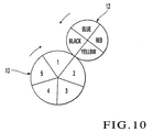
- Fig. 10 is a model view showing an impression cylinder for a sheet-fed offset rotary printing press according to the second embodiment of the present invention.
- the second embodiment is different from the first embodiment in that an impression cylinder 13 has a quintuple size, that five gripper devices are provided to the impression cylinder 13, and that five printing surfaces are formed on the outer surface of the impression cylinder 13.
- the blanket cylinder 12 is thrown on onto and off from the impression cylinder 13 by a cylinder throw-on/throw-off device 39 at appropriate timings in the same manner as with the impression cylinder having three printing surfaces described above.
- multicolor printing can be performed on five paper sheets gripped by the five gripper devices of the impression cylinder 13.
- the printing cylinder includes the plate cylinder 11 and the blanket cylinder 12 which is in contact with the plate cylinder 11, and the blanket cylinder 12 is brought into contact with the impression cylinder 13.
- the plate cylinder 11 may be brought into direct contact with the impression cylinder 13 without using any blanket cylinder 12. Only cases wherein the impression cylinder 13 has three printing surfaces and a case wherein the impression cylinder 13 has five printing surfaces have been described. It suffices if the impression cylinder 13 has an odd number of printing surfaces with respect to the four printing surfaces of the blanket cylinder 12, so that the printing surfaces of the impression cylinder 13 will not come into contact with the same corresponding printing surfaces of the blanket cylinder 12.
- the impression cylinder 13 is selectively thrown off from the blanket cylinder 12, so that another ink will not be printed on the printing surfaces of the impression cylinder 13. If the impression cylinder has only one printing surface, printing can be performed in the impression throw-on state. Depending on the arrangement of the four printing surfaces of the blanket cylinder, the impression cylinder can be thrown off selectively. Although printing is performed in the above embodiments in the order of black ⁇ blue ⁇ red ⁇ yellow, it can be performed in any printing order. As a sheet, a vinyl chloride sheet or film, or the like can be used.
Landscapes
- Engineering & Computer Science (AREA)
- Mechanical Engineering (AREA)
- Rotary Presses (AREA)
- Feeding Of Articles By Means Other Than Belts Or Rollers (AREA)
- Supply, Installation And Extraction Of Printed Sheets Or Plates (AREA)
Applications Claiming Priority (2)
| Application Number | Priority Date | Filing Date | Title |
|---|---|---|---|
| JP2004012245 | 2004-01-20 | ||
| JP2004012245A JP2005205630A (ja) | 2004-01-20 | 2004-01-20 | 枚葉輪転印刷機 |
Publications (1)
| Publication Number | Publication Date |
|---|---|
| EP1557263A1 true EP1557263A1 (de) | 2005-07-27 |
Family
ID=34631886
Family Applications (1)
| Application Number | Title | Priority Date | Filing Date |
|---|---|---|---|
| EP05000698A Withdrawn EP1557263A1 (de) | 2004-01-20 | 2005-01-14 | Bogenrotationsdruckmaschine |
Country Status (4)
| Country | Link |
|---|---|
| US (1) | US20050155503A1 (de) |
| EP (1) | EP1557263A1 (de) |
| JP (1) | JP2005205630A (de) |
| CN (1) | CN1644370A (de) |
Cited By (2)
| Publication number | Priority date | Publication date | Assignee | Title |
|---|---|---|---|---|
| EP1829683A3 (de) * | 2006-03-01 | 2008-05-07 | FUJIFILM Corporation | Auf der Druckpresse stattfindende Entwicklung sowie Druckverfahren und -vorrichtung |
| EP2039510A3 (de) * | 2007-09-19 | 2012-01-11 | Komori Corporation | Vorrichtung zur An- und Abstellen von Zylindern und Verfahren zur An- und Abstellen von Zylindern für eine Druckmaschine |
Families Citing this family (6)
| Publication number | Priority date | Publication date | Assignee | Title |
|---|---|---|---|---|
| US20060243148A1 (en) * | 2005-04-29 | 2006-11-02 | Mikhail Laksin | Flexible digital printing plates and process of digital printing |
| US20120274914A1 (en) * | 2011-04-27 | 2012-11-01 | Palo Alto Research Center Incorporated | Variable Data Lithography System for Applying Multi-Component Images and Systems Therefor |
| JP6091106B2 (ja) * | 2011-08-05 | 2017-03-08 | パロ・アルト・リサーチ・センター・インコーポレーテッドPalo Alto Research Center Incorporated | マーキング材料サブシステム |
| US9388319B2 (en) * | 2013-05-31 | 2016-07-12 | Xerox Corporation | Systems and methods for delivering aqueous pearlescent digital printing ink compositions using digital offset lithographic printing techniques |
| JP6270133B2 (ja) * | 2014-02-12 | 2018-01-31 | 株式会社小森コーポレーション | フレキシブル電子デバイス製造装置 |
| DE102016204221A1 (de) * | 2015-04-20 | 2016-10-20 | Heidelberger Druckmaschinen Ag | Druckwerk einer Bogendruckmaschine |
Citations (6)
| Publication number | Priority date | Publication date | Assignee | Title |
|---|---|---|---|---|
| DE4002563A1 (de) * | 1989-02-08 | 1990-08-09 | Polygraph Leipzig | Greiferwagenfuehrung |
| EP0591792A1 (de) * | 1992-10-01 | 1994-04-13 | Komori Corporation | Vorrichtung zum Abheben eines Zylinders |
| US5909708A (en) * | 1995-07-18 | 1999-06-08 | Koenig & Bauer-Albert Aktiengesellschaft | Sheet-fed offset rotary printing machine |
| US6050188A (en) * | 1995-06-30 | 2000-04-18 | Koenig & Bauer-Albert Aktiengesellschaft | Sheet-fed rotary press |
| US6302018B1 (en) * | 1999-07-19 | 2001-10-16 | Ryobi Ltd. | Offset printer having power transmission shut off mechanism |
| US20030164101A1 (en) * | 2002-03-04 | 2003-09-04 | Dagher Joseph G. | Color printing press |
Family Cites Families (13)
| Publication number | Priority date | Publication date | Assignee | Title |
|---|---|---|---|---|
| DE1235953B (de) * | 1965-03-17 | 1967-03-09 | Koenig & Bauer Schnellpressfab | Bogen-Offset-Rotationsdruckmaschine fuer wahlweisen Schoen- und Widerdruck oder Schoendruck |
| CH508480A (de) * | 1970-08-17 | 1971-06-15 | Max Dr Ras | Mehrfarben-Bogen-Offsetdruckverfahren, insbesondere Andruckverfahren, sowie Bogenoffsetpresse zur Durchführung des Verfahrens |
| US4509424A (en) * | 1982-04-22 | 1985-04-09 | De La Rue Giori S.A. | Convertible, multicolor, rotary printing press |
| US5185779A (en) * | 1987-08-05 | 1993-02-09 | Norbert Zawacki | Cellular alarm backup system |
| US4993059A (en) * | 1989-02-08 | 1991-02-12 | Cableguard, Inc. | Alarm system utilizing wireless communication path |
| JPH04115949A (ja) * | 1990-09-07 | 1992-04-16 | Mitsubishi Heavy Ind Ltd | 水着ローラの版胴への着タイミング |
| US5675626A (en) * | 1995-10-30 | 1997-10-07 | Davis; Ronnie D. | Cellular and battery backup telecommunication system |
| US6009807A (en) * | 1997-03-28 | 2000-01-04 | Dainippon Screen Mfg. Co., Ltd. | Printing apparatus |
| US6032037A (en) * | 1997-12-16 | 2000-02-29 | Sur-Gard Security Systems Ltd. | Alarm panel with cellular communications backup |
| JP2000127349A (ja) * | 1998-08-21 | 2000-05-09 | Komori Corp | 凹版印刷機 |
| US6263050B1 (en) * | 1998-12-18 | 2001-07-17 | Lucent Technologies Inc. | Method and system for responding to security system breaches via a wireless network |
| US6411802B1 (en) * | 1999-03-15 | 2002-06-25 | Bellsouth Intellectual Property Management Corporation | Wireless backup telephone device |
| US6532360B1 (en) * | 1999-12-14 | 2003-03-11 | M. Bennett Shaffer | Mobile security system with cellular transceiver, position reporting and remote actuation |
-
2004
- 2004-01-20 JP JP2004012245A patent/JP2005205630A/ja active Pending
-
2005
- 2005-01-14 EP EP05000698A patent/EP1557263A1/de not_active Withdrawn
- 2005-01-19 US US11/039,504 patent/US20050155503A1/en not_active Abandoned
- 2005-01-20 CN CN200510005514.7A patent/CN1644370A/zh active Pending
Patent Citations (6)
| Publication number | Priority date | Publication date | Assignee | Title |
|---|---|---|---|---|
| DE4002563A1 (de) * | 1989-02-08 | 1990-08-09 | Polygraph Leipzig | Greiferwagenfuehrung |
| EP0591792A1 (de) * | 1992-10-01 | 1994-04-13 | Komori Corporation | Vorrichtung zum Abheben eines Zylinders |
| US6050188A (en) * | 1995-06-30 | 2000-04-18 | Koenig & Bauer-Albert Aktiengesellschaft | Sheet-fed rotary press |
| US5909708A (en) * | 1995-07-18 | 1999-06-08 | Koenig & Bauer-Albert Aktiengesellschaft | Sheet-fed offset rotary printing machine |
| US6302018B1 (en) * | 1999-07-19 | 2001-10-16 | Ryobi Ltd. | Offset printer having power transmission shut off mechanism |
| US20030164101A1 (en) * | 2002-03-04 | 2003-09-04 | Dagher Joseph G. | Color printing press |
Cited By (2)
| Publication number | Priority date | Publication date | Assignee | Title |
|---|---|---|---|---|
| EP1829683A3 (de) * | 2006-03-01 | 2008-05-07 | FUJIFILM Corporation | Auf der Druckpresse stattfindende Entwicklung sowie Druckverfahren und -vorrichtung |
| EP2039510A3 (de) * | 2007-09-19 | 2012-01-11 | Komori Corporation | Vorrichtung zur An- und Abstellen von Zylindern und Verfahren zur An- und Abstellen von Zylindern für eine Druckmaschine |
Also Published As
| Publication number | Publication date |
|---|---|
| CN1644370A (zh) | 2005-07-27 |
| US20050155503A1 (en) | 2005-07-21 |
| JP2005205630A (ja) | 2005-08-04 |
Similar Documents
| Publication | Publication Date | Title |
|---|---|---|
| EP0751875B1 (de) | Mehrfarben-druckmaschine | |
| US6050188A (en) | Sheet-fed rotary press | |
| US5479856A (en) | Rotary printing press for two-sided printing of sheets | |
| US4509424A (en) | Convertible, multicolor, rotary printing press | |
| US5909708A (en) | Sheet-fed offset rotary printing machine | |
| EP2583828B1 (de) | Kombinationsdruckmaschine | |
| US6283025B1 (en) | Multicolor sheet-fed printing press | |
| US6474231B1 (en) | Multi-color printing press with common blanket cylinder | |
| US5467710A (en) | Rotary printing press for two-sided printing of sheets | |
| JPH0241415B2 (de) | ||
| EP1557263A1 (de) | Bogenrotationsdruckmaschine | |
| US8733247B2 (en) | Sheet-fed offset printing press for printing on both sides of sheets | |
| JPS6127257A (ja) | ドライオフセツト凹版印刷機 | |
| JPH0321346B2 (de) | ||
| US8181575B2 (en) | Method of variable cutoff printing in a press having a common blanket cylinder | |
| JPS60127154A (ja) | 枚葉オフセツト印刷機 | |
| US6546862B1 (en) | Method and device for producing a multicolor print | |
| RU2156696C2 (ru) | Листовая ротационная машина для офсетной печати | |
| JPH0222058A (ja) | 多色刷オフセット印刷機 | |
| MXPA96004776A (en) | Multi-print press | |
| JP2013075516A (ja) | ザンメル印刷機及び該ザンメル印刷機を含む組合せ印刷機 |
Legal Events
| Date | Code | Title | Description |
|---|---|---|---|
| PUAI | Public reference made under article 153(3) epc to a published international application that has entered the european phase |
Free format text: ORIGINAL CODE: 0009012 |
|
| AK | Designated contracting states |
Kind code of ref document: A1 Designated state(s): AT BE BG CH CY CZ DE DK EE ES FI FR GB GR HU IE IS IT LI LT LU MC NL PL PT RO SE SI SK TR |
|
| AX | Request for extension of the european patent |
Extension state: AL BA HR LV MK YU |
|
| 17P | Request for examination filed |
Effective date: 20051128 |
|
| AKX | Designation fees paid |
Designated state(s): AT BE BG CH CY CZ DE DK EE ES FI FR GB GR HU IE IS IT LI LT LU MC NL PL PT RO SE SI SK TR |
|
| STAA | Information on the status of an ep patent application or granted ep patent |
Free format text: STATUS: THE APPLICATION IS DEEMED TO BE WITHDRAWN |
|
| 18D | Application deemed to be withdrawn |
Effective date: 20060614 |