EP1557298A1 - Attelage de remorque - Google Patents
Attelage de remorque Download PDFInfo
- Publication number
- EP1557298A1 EP1557298A1 EP05000638A EP05000638A EP1557298A1 EP 1557298 A1 EP1557298 A1 EP 1557298A1 EP 05000638 A EP05000638 A EP 05000638A EP 05000638 A EP05000638 A EP 05000638A EP 1557298 A1 EP1557298 A1 EP 1557298A1
- Authority
- EP
- European Patent Office
- Prior art keywords
- trailer
- coupling according
- trailer coupling
- blocking
- bearing
- Prior art date
- Legal status (The legal status is an assumption and is not a legal conclusion. Google has not performed a legal analysis and makes no representation as to the accuracy of the status listed.)
- Granted
Links
- 230000008878 coupling Effects 0.000 title claims description 59
- 238000010168 coupling process Methods 0.000 title claims description 59
- 238000005859 coupling reaction Methods 0.000 title claims description 59
- 230000000903 blocking effect Effects 0.000 claims description 82
- 238000006073 displacement reaction Methods 0.000 claims description 27
- 230000009471 action Effects 0.000 claims description 13
- 230000004913 activation Effects 0.000 claims description 7
- 230000000694 effects Effects 0.000 claims description 3
- 230000003993 interaction Effects 0.000 claims description 2
- 230000007704 transition Effects 0.000 claims description 2
- 230000000284 resting effect Effects 0.000 abstract description 2
- 230000002349 favourable effect Effects 0.000 description 8
- 230000008901 benefit Effects 0.000 description 4
- 238000004146 energy storage Methods 0.000 description 3
- 230000006835 compression Effects 0.000 description 2
- 238000007906 compression Methods 0.000 description 2
- 230000015572 biosynthetic process Effects 0.000 description 1
- 230000010354 integration Effects 0.000 description 1
- 230000002093 peripheral effect Effects 0.000 description 1
Images






Classifications
-
- B—PERFORMING OPERATIONS; TRANSPORTING
- B60—VEHICLES IN GENERAL
- B60D—VEHICLE CONNECTIONS
- B60D1/00—Traction couplings; Hitches; Draw-gear; Towing devices
- B60D1/24—Traction couplings; Hitches; Draw-gear; Towing devices characterised by arrangements for particular functions
- B60D1/26—Traction couplings; Hitches; Draw-gear; Towing devices characterised by arrangements for particular functions for remote control, e.g. for releasing
-
- B—PERFORMING OPERATIONS; TRANSPORTING
- B60—VEHICLES IN GENERAL
- B60D—VEHICLE CONNECTIONS
- B60D1/00—Traction couplings; Hitches; Draw-gear; Towing devices
- B60D1/48—Traction couplings; Hitches; Draw-gear; Towing devices characterised by the mounting
- B60D1/54—Traction couplings; Hitches; Draw-gear; Towing devices characterised by the mounting collapsible or retractable when not in use, e.g. hide-away hitches
Definitions
- Trailer coupling for motor vehicles comprising a bearing element, one opposite the bearing element between a working position and a rest position pivotable about a pivot axis of a pivot bearing and at least in the working position between a pivoting position and a fixing position in the direction of the pivot axis displaceable trailer element and a Fixing device, with which the trailer element at least in the working position immovably fixed on the bearing element upon reaching the fixing position is.
- Such towbars are for example from DE 100 17 013 known.
- the invention is therefore based on the object with a trailer hitch To provide simplified fixation of the trailer element on the bearing element.
- the trailer element is a bearing body has, that the bearing element has a receiving body, in which engages the bearing body at least in the fixing position and opposite which the bearing body between the pivot position and the fixing position in a direction of displacement and vice versa is movable, and that the fixing a the bearing body against movement in the Displacement direction relative to the receiving body blocking blocking device having at least one arranged in one of the elements and from a release position with a force in the direction of a Locking position movable locking body and at least one on the other having the elements arranged blocking surface, which the locking body in the Locking position engages behind.
- the advantage of the solution according to the invention is the fact that with the Providing a locking body and a blocking surface an easy way a blockage of the bearing body is given in the fixing position, the In addition, a sufficient reliability in the locked position of Locking body offers.
- the towbar both in the Swivel position and in the fixing position relative to the receiving body stores, the storage in the pivoting position a rotatable Storage represents, while in the fixing position, the storage of the bearing body in the receiving body in the sense of a secure support of the Towing element against the bearing element takes place.
- a particularly advantageous embodiment of the trailer element provides that this a first, the coupling ball bearing end and a second free End has.
- the bearing body to arranged the trailer between the ball neck and the free end is.
- the receiving body a first opening through which the bearing body starting engages the ball neck in the receiving body, and a second, the first Opening opposite opening.
- the blocking device having a blocking body drive, with which the locking body from one of these from the release position in the direction of the blocking position moving force is acted upon.
- Such a blocking body drive can in different ways be educated.
- the locking body directly with a Act on compression spring.
- a particularly expedient solution provides that the blocking body drive a Drive element having, with which the locking body of the release position is movable in the locked position.
- the drive element is characterized by an elastic energy storage acted upon, so that the possibility exists, the drive element always with the force of the elastic force accumulator acted upon to keep and thus always be effective on the lock body.
- the drive element in such a way that by relative rotation thereof to the locking body, a displacement of the at least one locking body is possible.
- the operation of the lock body can thereby be cheap and safe realize when the drive element is a drive link with a recording in which the at least one locking body in the release position dips, and a sliding surface with which the at least one locking body is movable from the release position to the blocking position.
- a Such displacement surface can be in a simple manner and in particular safely move the locking body from the release position to the locked position.
- a wedge surface connects, which the locking body in the locked position acted upon adjusting in the direction of movement.
- the blocking device form-fitting Fixing the fixer holds in play-free system and thus Overall, the fixation of the trailer element clearance relative to the bearing element can be done.
- the interaction of the locking body with the blocking surface results in particularly simple manner, an admission of the bearing body in the direction the fixing position when the blocking surface is inclined or inclined to the direction of movement runs.
- the at least one locking body and the blocking body drive in the bearing body is arranged and thus mitbewegbar with the bearing body.
- the blocking device on the one Lock actuator acting actuator comprises, with which on the drive element against the force of the elastic force accumulator is acted upon.
- an actuating element of Actuator protrudes beyond the free end of the trailer element and thus via the actuating element an action on the drive element is possible.
- this is the actuator coaxial with the pivot axis arranged so that a turning of the trailer element to the Swivel axle can be intercepted constructively in a simple manner.
- the actuator with a rotary joint to provide.
- the action on the blocking body drive can be realized particularly easily, when the actuator for lifting the on the drive element acting force of the elastic force store in its over the free end of the hitch protruding area in the direction of the free End of the trailer element can be acted upon.
- the actuator at in Release position standing blocking body the trailer from the fixing position is slidable in the pivoting position, so that the actuating device not only used to act on the blocking body drive, to the at least one locking body from the locking position in the To move release position, but at the same time the actuator can also be used to the hitch element of the fixing position actively move to the pivot position.
- the actuator advantageously can not be only use to move the hitch to the pivot position, but also to the hitch in the pivot position in Defines the direction of displacement defined, that is in the direction of displacement in a defined, the pivot position assigned position to hold relative to the bearing element, so that the bearing body the possibility has, together with the receiving body, the pivot bearing for the To form trailer element.
- the action of the actuator on the actuator can done in a variety of ways.
- an embodiment provides that the actuating element with a Guide lever of the actuator is coupled.
- the actuating element as a rack is formed, which with a pinion of the actuator meshes, so that with the actuator is possible through Turning the pinion to act on the actuator.
- each actuator with an impact element, preferably for manual action on the Actuator, provided.
- the at least one blocking body by Locking the drive element set relative to the bearing body and thus the force of the elastic force accumulator of the locking body drive on to block the blocking body.
- the at least one locking body in lateral Guided openings of the trailer element in the direction of movement arranged.
- the guide openings can in principle at any point of the trailer element be arranged. It is particularly useful if the lateral Guiding openings arranged near the free end of the trailer element are.
- the drive element in the hitch were also no further information. So it is preferably provided that the drive element in a recess in the trailer element is arranged.
- the recess is designed so that they are different from a provided at the free end of the hitch element opening in the Anberichtelement hineinerstreckt.
- the recess could be parallel or oblique to the pivot axis run.
- the elastic energy storage on a bottom opposite the opening the recess is supported.
- the bearing element has a receiving body with a Has opening from which starting a bearing body of the trailer element engages in the receiving body, and that the trailer element a having first positive locking element, which in the pivoting position of the Towing element disengaged with a second provided on the receiving body Positive locking element is and which at least in the working position when moving the trailer element from the pivot position in the fixing position with the second positive locking element of the receiving body in Intervention can be brought.
- the second interlocking element in a frontal region of the receiving body is arranged.
- the second positive locking element in one piece the receiving body is formed.
- the first positive locking element is integrally formed on the trailer element.
- the position of the first positive locking element is preferably selected so that the first positive locking element in the region of a transition from the ball neck to Bearing body is arranged.
- the trailer element to be able to fix, it is preferably provided that the receiving body a having third positive locking element, with which the first positive locking element in the rest position is engageable.
- the third positive locking element is identical to that formed second positive locking element.
- the bearing body a guideway, on which a trailer element arranged Guide element rests when the hitch outside the Working position and the resting position.
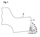
- a first exemplary embodiment of a trailer coupling according to the invention is As shown in Fig. 1, on a vehicle body 10, between a rear side 14 of the rear portion 12 and a bumper 16 is mounted. In one formed between the rear 14 and the bumper 16 Gap 18 and above a lower edge 22 of the bumper 16 is a Bearing element 20 of the hitch arranged, which by a with the vehicle body 10 connected cross member 24, which is also in Interspace 18 extends, is held.
- the bearing element 20 On the bearing element 20 is a designated as a whole with 30 trailer element movably mounted, wherein the trailer element a ball neck 32nd which carries a coupling ball 36 at a first end 34.
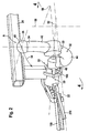
- the coupling ball 36 In a working position shown in Fig. 2, the coupling ball 36 is arranged so that they from a longitudinal center plane 38 of the vehicle body 10th is cut symmetrically and thus the longitudinal center plane through a ball center 40 of the coupling ball 36 runs.
- first region 42 of the ball neck 32 also symmetrical to the Longitudinal center plane 28 and then leads by means of a bend 44 to a second end 48 of the ball neck 32nd
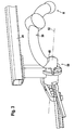
- the hitch 30 is in turn by means of a 50 as a whole designated pivot bearing about a pivot axis 52 on the bearing element 20th pivotally mounted, wherein the hitch 30 by pivoting order the pivot axis 52 either in the working position A shown in FIG is positionable or in one shown in Fig. 3 substantially by the bumper 16 covered and lying in the gap 18 rest position R, wherein a pivoting movement about the pivot axis 52 of the Working position A in the rest position R in a counterclockwise direction extending pivoting direction 54 by an angle of more than 180 ° takes place and in the reverse manner a pivoting movement from the rest position R in the working position A clockwise.
- the pivot axis 52 extends, as shown in Fig. 2 and 3, obliquely to Longitudinal center plane 38 and preferably also obliquely to a horizontal Level 58, opposite to the horizontal plane 58 opposite to falling in one direction of travel.
- the ball neck 32 emerges during pivoting between the working position A and the rest position R respectively under the Lower edge 22 of the bumper 16 therethrough.
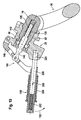
- the pivot bearing 50 is formed by one of Bearing element 20 included receiving body, which from a ball neck 32 facing opening 62 starting a first to the pivot axis 52nd cylindrical receiving surface 64 and facing away on one of the opening 62 Side of the first cylindrical receiving surface 64 arranged second cylindrical receiving surface 66 which has a smaller diameter has as the first cylindrical receiving surface, and which in continuation the second cylindrical receiving surface 66 a third cylindrical Receiving surface 68 also with respect to the second cylindrical Receiving surface 66 reduced diameter, which on one of the first cylindrical receiving surface 64 opposite side of the second cylindrical receiving surface 66 is arranged.
- the receiving body 60 sits a designated as a whole with 70 bearing body, which in a fixing position shown in Fig. 4 with a first to the longitudinal axis 71 and thus also to the pivot axis 52 cylindrical Lateral surface 74 bears against the first cylindrical receiving surface 64, which with a second to the pivot axis 52 cylindrical surface 76th abuts the second cylindrical receiving surface 66 and which with a third cylindrical surface 78 on the third cylindrical receiving surface 68 is present.
- the bearing body 70 also continues to settle on the third cylindrical surface 78 continues with a guide section 80, which extends up to a second one opposite the first end 72 of the bearing body 70 End 82 of the bearing body 70 extends.
- Guide holes 84 lock body 88 a designated as a whole with 90 Blocking arranged in a direction of movement 92 transversely to the Pivot axis 52 are movable in such a way that with these in an insert body 94 of the bearing member 20 and provided by a to the Swivel axis 52 circumferential groove 96 formed locking surfaces 98 engaged behind are, which run obliquely to the direction of movement 92.
- the insert body 94 is arranged in the bearing element 20, that this adjoins the receiving body 60 and preferably in one Recess 102 sits, facing away from one of the opening 62 Opening 104 of the bearing member 20 hineinerstreckt into this, so that the insert body 94 concentric with the pivot axis 52 in the bearing element 20th is held and with a subsequent to the groove 96 cylindrical Inner surface 106 in alignment with the third cylindrical receiving surface 68 to to an opening 108 extends.
- the drive element 112 has to move the locking body 88 a Drive link 120 on which a receptacle 122 for the locking body 88, a itself to the receptacle 122 subsequent displacement surface 124 for the locking body 88 and a subsequent to the displacement surface 124 wedge surface 126 for the locking body 88 includes.
- the drive element 112 of the locking body drive is also still with a Guiding pin 128 provided, which in an interior of an elastic force accumulator 130 engages, located on a bottom 132 of the receiving bore 114 supported on the one hand and on the other hand, the drive element 112 in the area an annular flange 134 acted upon by a force such that the drive element 112 always has the tendency to go so far towards an active Move position that the drive link 120 with the wedge surface 126 the acted in blocking position blocking body 88 and thus the locking body 88 always act with a force against the locking surfaces 98, as shown in Fig. 4 is shown, so that the bearing body 70 also in the fixing position as far as possible into the receiving body 60 is retracted.
- the blocking device comprises 90 an actuating device designated as a whole by 140, which an integrally formed on the drive element 112 actuator 142, which is coaxial with the pivot axis 52 in continuation of the drive element 112 through the opening 118 and over the second End 82 of the bearing body 70.00erstreckt and a joint 144 with a guide lever 146 is connected, which on one side of the bearing element 20 is mounted with a pivot joint 148 and starting from the pivot joint 148 via the opening 108 of the receiving element 20th stretched out and on his the pivot joint 148 opposite Side carries an actuating lever 150.
- the guide lever 146 moves in the direction of the opening 108 and thus there is an action on the actuating element 142 in an actuating direction 144, in which the actuating element 142, the drive element 112 the blocking body drive 110 against the action of the elastic force accumulator 130 einschiebt in the receiving bore 114.
- the drive link 120 no longer loads the blocking bodies 88 with it the wedge surfaces 126 but first with the sliding surfaces 124 and then pushed further until, as shown in Fig. 5, the locking body 88 in the receptacle 122 can dive and thus from its locked position can move out into their release position, in which the locking body 88 no longer survive on the outside of the guide portion 80, so that the guide portion 80 in the direction of the third cylindrical receiving surface 68 is displaceable, as shown in Fig. 6.
- the entire bearing body 70 is in a pivoting position shifted, in which the entire trailer element 30 about the pivot axis 52 is freely rotatable.
- the bearing body 70 By moving the bearing body 70 opposite to the direction of displacement 156, for example, the first cylindrical lateral surface 74 so far moved that this offset in the direction of the longitudinal axis 71 relative to the first cylindrical receiving surface 64 is arranged.
- the form-locking body 160 has two wedge-shaped to each other extending positive engagement surfaces 170a, 170b, which at corresponding Molded surfaces 162a, 162b of the working position-side positive locking receptacle 162 can be applied, thereby thereby upon application of the Positive locking body 160 in the direction of displacement 156 in the direction of the fixing position the first form-locking surfaces 170a, 170b abut against the positive-locking surfaces 172a, 172b of the working position-side positive locking receptacle 162nd can be created without play.
- the positive-locking body 160 is opposed another first positive locking element in the form of another positive-locking body 180 provided, which due to the perspective view only in the rest position R is recognizable.
- This further form-fitting body 180 is formed in principle the same as the Positive locking body 160 and, as shown in Fig. 8, in the rest position R in another third positive locking element in the form of a rest side Positive locking receptacle 182 insertable. Also, the other positive locking body 180th has positive engagement surfaces 190a, 190b, which with positive locking surfaces 192a, 192b the rest position-side positive locking receptacle 182 during displacement of the same can be brought into engagement by the pivoting position in the fixing position.
- the guide pin 200 on the guideway 202 itself can be supported outside the working position A and the rest position R, ensures that the first positive locking body 160 only in the working position A in the rest position R in the direction of displacement 156 of the Pivoting position can move into the fixing position and thus only in the for this intended job-related form fit receptacle and the Reststaubungs worne recording can occur.
- the guide pin 200 and the guide track 202 thus prevent that the bearing body 70 in all intermediate positions between the working position A and move the rest position R from the pivot position to the fixing position can.
- the inactive position of the drive element shown in Fig. 6 is also characterized 112 of the blocking body drive 110 maintained because the in the Release position blocking body 88 a relative movement of the Drive element 112 relative to the bearing body 70 in the activation direction 116 prevent, because the locking body 88 based in this Position on the third cylindrical receiving surface 68 of the receiving body 60 off.
- the bearing body 70 can about the pivot axis 52nd rotate while the actuator 142 and the drive element 112 be held by the guide lever 146 rotationally fixed to the pivot axis 52 and thus do not participate in the rotation, but remain rotationally fixed, while the bearing body 70 with the locking bodies 88 around the drive element 112th turns around.
- Figs. 9 to 12 shown in Figs. 9 to 12 are those elements identical to those of the first embodiment are provided with the same reference numerals, so that in terms of Description of the same fully to the comments on the first Embodiment can be referenced.
- a handle member 226 is provided, with which on the locking pin 220 such can be acted that this relative to a release direction 228 to the actuating lever 150 'is displaced so far that this is the bolt receptacle 224 leaves and thus the operating lever 150 'in already described manner in the pulling direction 152 is pivotable to means of the Actuator 142, the drive element 112 in the operating direction 154 opposite to the force of the elastic force accumulator 130 in move its inactive position and at the same time the bearing body 70 relative to the receiving body 60 from the fixing position in the pivot position in which a pivoting of the same in the same way as in Connection with the first embodiment described is possible.
- the Actuator 140 ' in particular the guide lever 146 is not direct actuated by the actuating lever 150, but via a cable pulling device 230, which creates the possibility, via a cable 232 the Force to a provided from a suitable location operating lever to transfer.
- the third embodiment is designed in the same way as the first embodiment, so that with respect to the other elements in full to the comments on the first embodiment reference is taken and also provide the same parts with the same reference numerals are.
- FIGS. 13 to 16 are those elements identical to those of the first embodiment are also provided with the same reference numerals, so that in terms of Description of the same fully to the comments on the first embodiment Reference can be made.
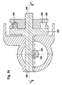
- the actuator 140 designed as a rotary drive and comprises as actuating element 142 'a rack 242, which with a pinion 244 of a drive shaft 246 is engaged, wherein the Drive shaft 246 by a rotary drive 248 with a freewheel 250 and a latching device 252 is driven.
- the freewheel 250 is formed by a freewheel disk 254, which, as shown in FIG. 14, carries a driver 256, which in a driving groove 258 of a Mit Conversecase 260 engages, which rotatably relative to the freewheel disk 254 and is rotatably mounted on the drive shaft 246.
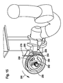
- the cam groove 258 has, as shown in Fig. 15, a first end 262 and a second end 264, between which the driver 256 can freely move in the driving groove 258.
- the drive plate 260 is on its outer peripheral side with a Control link 266 provided, with which a control pin 268 of a detent body 270 of the latching device 252 is displaceable, to the effect that the Locking body 270 against the force of a spring 272 in an unlocking direction 274 is movable.
- the latching body 270 further has a latching nose 276, which with a Detent recess 278 in the freewheel disk 254 is then engageable, when the rotatably coupled to the drive shaft 246 freewheel disk 254 in one of the active position of the drive member 112 corresponding position stands. In this position, the locking lug 276 of the locking body 270 is the Rotary movement of the freewheel disk 254 blocked and thus also the Actuator 142 'against movement in the actuating direction 154th secured.
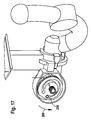
- the driver disk 260 may first be in one Turning direction 280 are rotated until the driver 256 at the end 262 the cam groove 258 is applied (FIG. 16). This way is sufficient to use the control cam 266 act on the control pin 268 of the locking body 270 and thus the locking body 270 against the force of the spring 272 to move in release direction 274 and thus the rotational movement of the Freewheel 254 free to give.
- the freewheel disk 254 is entrained in that the driver 256 at the end 262 of the cam groove 258 rests and with the drive plate 260 is further rotated as shown in Fig. 16 and 17.
- the pulling action can now account for the cable 278 and the drive plate 260 has the opportunity acted upon by a torsion spring 282 opposite to the direction of rotation 280 back to their original position, while the freewheel disk 254 with the driver 256 in one of the inactive position of the drive element 112 and the pivotal position of the trailer element 30 corresponding Stance can persist until the hitch 30 either in the Working position A or the rest position R again in the direction of displacement 156 is moved to the fixing position and the drive element 112 in the Fixation position goes into its active position.
- This can then be the driver 256 move back freely in the position shown in Fig. 15 and it is again a rotationally fixed locking the freewheel disk 254 characterized, in that the latching nose 276 of the latching body 270 dips into the latching recess 278.
Landscapes
- Engineering & Computer Science (AREA)
- Transportation (AREA)
- Mechanical Engineering (AREA)
- Agricultural Machines (AREA)
- Transmission Devices (AREA)
- Mounting Of Bearings Or Others (AREA)
- Rolling Contact Bearings (AREA)
- Massaging Devices (AREA)
- Percussion Or Vibration Massage (AREA)
Applications Claiming Priority (2)
| Application Number | Priority Date | Filing Date | Title |
|---|---|---|---|
| DE102004004503.8A DE102004004503B4 (de) | 2004-01-22 | 2004-01-22 | Anhängekupplung |
| DE102004004503 | 2004-01-22 |
Publications (3)
| Publication Number | Publication Date |
|---|---|
| EP1557298A1 true EP1557298A1 (fr) | 2005-07-27 |
| EP1557298B1 EP1557298B1 (fr) | 2008-03-05 |
| EP1557298B2 EP1557298B2 (fr) | 2013-02-13 |
Family
ID=34625810
Family Applications (1)
| Application Number | Title | Priority Date | Filing Date |
|---|---|---|---|
| EP05000638A Expired - Lifetime EP1557298B2 (fr) | 2004-01-22 | 2005-01-14 | Attelage de remorque |
Country Status (4)
| Country | Link |
|---|---|
| US (1) | US7216886B2 (fr) |
| EP (1) | EP1557298B2 (fr) |
| AT (1) | ATE388030T1 (fr) |
| DE (2) | DE102004004503B4 (fr) |
Cited By (6)
| Publication number | Priority date | Publication date | Assignee | Title |
|---|---|---|---|---|
| EP1902870A1 (fr) * | 2006-09-18 | 2008-03-26 | WESTFALIA - Automotive GmbH | Dispositif de remorque pour un véhicule de traction |
| EP1946947A1 (fr) * | 2007-01-19 | 2008-07-23 | WESTFALIA - Automotive GmbH | Dispositif de remorque doté d'un dispositif de verrouillage avec bague d'actionnement |
| EP2233326A1 (fr) * | 2009-03-25 | 2010-09-29 | SCAMBIA Industrial Developments Aktiengesellschaft | Attelage |
| EP2567835B1 (fr) | 2011-09-12 | 2016-08-10 | Scambia Holdings Cyprus Limited | Attelage |
| EP4124475A1 (fr) * | 2021-07-26 | 2023-02-01 | Zhejiang Zhiyou Automotive Technology Co., Ltd. | Coupleur d'attelage de remorque |
| EP2657051B2 (fr) † | 2012-04-25 | 2023-08-23 | WESTFALIA - Automotive GmbH | Agencement de couplage pour un support de toit |
Families Citing this family (25)
| Publication number | Priority date | Publication date | Assignee | Title |
|---|---|---|---|---|
| DE102005032474A1 (de) | 2005-07-07 | 2007-01-11 | Oris Fahrzeugteile Hans Riehle Gmbh | Anhängevorrichtung |
| DE102005053177A1 (de) * | 2005-11-03 | 2007-05-10 | Scambia Industrial Developments Aktiengesellschaft | Betätigungseinrichtung |
| DE102006035261A1 (de) † | 2006-07-29 | 2008-01-31 | Scambia Industrial Developments Aktiengesellschaft | Anhängekupplung |
| DE102007003773A1 (de) * | 2007-01-19 | 2008-07-24 | Westfalia-Automotive Gmbh | Anhängevorrichtung für ein Zugfahrzeug |
| DE102008030626A1 (de) * | 2008-06-23 | 2009-12-31 | Scambia Industrial Developments Aktiengesellschaft | Anhängekupplung |
| USD623561S1 (en) * | 2009-04-24 | 2010-09-14 | Curt Manufacturing, Inc. | Bicolored curved ball hitch |
| USD610051S1 (en) * | 2009-04-24 | 2010-02-16 | Curt Manufacturing, Inc. | Sided drop ball hitch |
| USD610954S1 (en) * | 2009-04-24 | 2010-03-02 | Curt Manufacturing, Inc. | Curved ball hitch |
| USD623563S1 (en) * | 2009-04-24 | 2010-09-14 | Curt Manufacturing, Inc. | Bicolored sided drop ball hitch |
| USD623098S1 (en) * | 2009-04-24 | 2010-09-07 | Curt Manufacturing, Inc. | Bicolored drop ball hitch |
| USD610493S1 (en) * | 2009-04-24 | 2010-02-23 | Curt Manufacturing, Inc. | Drop ball hitch |
| US20100270774A1 (en) * | 2009-04-28 | 2010-10-28 | Midway Products Group, Inc. | Rotatable Trailer Hitch |
| DE102013007114A1 (de) * | 2013-04-21 | 2014-10-23 | Westfalia-Automotive Gmbh | Anhängekupplung |
| NO20130966A1 (no) | 2013-07-11 | 2015-01-12 | Smart Patents As | System og fremgangsmåte for automatisk å koble en tilhenger til et kjøretøy |
| US10556473B2 (en) | 2013-07-11 | 2020-02-11 | Smart Patents As | System and method for connecting or disconnecting a trailer to a vehicle |
| DE102015100490A1 (de) * | 2015-01-14 | 2016-07-14 | Scambia Holdings Cyprus Limited | Anhängekupplung |
| DE202015103207U1 (de) * | 2015-06-17 | 2016-09-20 | Westfalia-Automotive Gmbh | Anhängekupplung mit einer Aufnahmehülse |
| NO20161592A1 (en) | 2016-10-04 | 2018-04-05 | Smart Patents As | Trailer for connecting to a vehicle, and trailer coupler |
| US11007831B2 (en) | 2017-09-01 | 2021-05-18 | B & W Custom Truck Beds, Inc. | Vehicle trailer hitch assembly |
| DE102018124518A1 (de) * | 2018-10-04 | 2020-04-09 | ACPS Automotive GmbH | Anhängekupplung |
| SE544412C2 (en) * | 2019-03-12 | 2022-05-10 | Brink Towing Systems B V | Retractable towing hook arrangement |
| DE102019109398B4 (de) * | 2019-04-10 | 2021-05-27 | Dr. Ing. H.C. F. Porsche Aktiengesellschaft | Anhängerkupplung |
| DE102020114231A1 (de) | 2020-05-27 | 2021-12-02 | ACPS Automotive GmbH | Anhängevorrichtung |
| NO346568B1 (en) * | 2020-05-29 | 2022-10-10 | Smart Patents As | Trailer coupling assembly and vehicle with trailer coupling assembly |
| DE102020128980A1 (de) * | 2020-11-03 | 2022-05-05 | Westfalia-Automotive Gmbh | Anhängekupplung mit einer Verriegelungseinrichtung |
Citations (6)
| Publication number | Priority date | Publication date | Assignee | Title |
|---|---|---|---|---|
| EP1024036A1 (fr) * | 1999-01-21 | 2000-08-02 | ORIS FAHRZEUGTEILE HANS RIEHLE GmbH | Attelage de remorque |
| DE10017013A1 (de) | 2000-04-05 | 2001-10-18 | Oris Fahrzeugteile Riehle H | Anhängekupplung |
| EP1275533A2 (fr) * | 2001-07-14 | 2003-01-15 | FAC Frank Abels Consulting & Technology GmbH | Attelage de remorque |
| EP1288026A1 (fr) * | 2001-09-03 | 2003-03-05 | ORIS FAHRZEUGTEILE HANS RIEHLE GmbH | Attelage de remorque |
| EP1428697A1 (fr) * | 2002-11-13 | 2004-06-16 | Westfalia Automotive GmbH & Co. KG | Dipositif d'attelage |
| EP1504928A1 (fr) * | 2003-08-08 | 2005-02-09 | Westfalia Automotive GmbH & Co. KG | Attache remorque |
Family Cites Families (7)
| Publication number | Priority date | Publication date | Assignee | Title |
|---|---|---|---|---|
| DE29601156U1 (de) | 1996-01-24 | 1996-03-28 | Westfalia-Werke Knöbel GmbH & Co., 33378 Rheda-Wiedenbrück | Kupplungskugelträger für Fahrzeuganhängerkupplungen |
| DE19612961A1 (de) * | 1996-04-01 | 1997-10-02 | Oris Fahrzeugteile Riehle H | Anhängekupplung |
| DE19848487A1 (de) * | 1998-10-21 | 2000-05-04 | Oris Fahrzeugteile Riehle H | Anhängekupplung |
| DE10045296A1 (de) | 1999-10-04 | 2001-04-05 | Eberhardt Peka Fahrzeug | Anhängerkupplung für Kraftfahrzeuge |
| DE20120530U1 (de) | 2001-12-19 | 2002-05-23 | WESTFALIA-Automotive GmbH & Co. KG, 33378 Rheda-Wiedenbrück | Anhängervorrichtung für Kraftfahrzeuge |
| DE10320302A1 (de) | 2003-05-07 | 2004-12-09 | Westfalia-Automotive Gmbh & Co. Kg | Anhängekupplung für Kraftfahrzeuge |
| US6860503B2 (en) * | 2002-11-13 | 2005-03-01 | Westfalia-Automotive Gmbh & Co. Kg | Retractile motor-vehicle trailer hitch |
-
2004
- 2004-01-22 DE DE102004004503.8A patent/DE102004004503B4/de not_active Expired - Lifetime
-
2005
- 2005-01-14 AT AT05000638T patent/ATE388030T1/de not_active IP Right Cessation
- 2005-01-14 DE DE502005003040T patent/DE502005003040D1/de not_active Expired - Lifetime
- 2005-01-14 EP EP05000638A patent/EP1557298B2/fr not_active Expired - Lifetime
- 2005-01-18 US US11/039,081 patent/US7216886B2/en not_active Expired - Lifetime
Patent Citations (6)
| Publication number | Priority date | Publication date | Assignee | Title |
|---|---|---|---|---|
| EP1024036A1 (fr) * | 1999-01-21 | 2000-08-02 | ORIS FAHRZEUGTEILE HANS RIEHLE GmbH | Attelage de remorque |
| DE10017013A1 (de) | 2000-04-05 | 2001-10-18 | Oris Fahrzeugteile Riehle H | Anhängekupplung |
| EP1275533A2 (fr) * | 2001-07-14 | 2003-01-15 | FAC Frank Abels Consulting & Technology GmbH | Attelage de remorque |
| EP1288026A1 (fr) * | 2001-09-03 | 2003-03-05 | ORIS FAHRZEUGTEILE HANS RIEHLE GmbH | Attelage de remorque |
| EP1428697A1 (fr) * | 2002-11-13 | 2004-06-16 | Westfalia Automotive GmbH & Co. KG | Dipositif d'attelage |
| EP1504928A1 (fr) * | 2003-08-08 | 2005-02-09 | Westfalia Automotive GmbH & Co. KG | Attache remorque |
Cited By (8)
| Publication number | Priority date | Publication date | Assignee | Title |
|---|---|---|---|---|
| EP1902870A1 (fr) * | 2006-09-18 | 2008-03-26 | WESTFALIA - Automotive GmbH | Dispositif de remorque pour un véhicule de traction |
| EP1902871B2 (fr) † | 2006-09-18 | 2012-11-28 | WESTFALIA - Automotive GmbH | Attelage |
| EP1946947A1 (fr) * | 2007-01-19 | 2008-07-23 | WESTFALIA - Automotive GmbH | Dispositif de remorque doté d'un dispositif de verrouillage avec bague d'actionnement |
| EP2233326A1 (fr) * | 2009-03-25 | 2010-09-29 | SCAMBIA Industrial Developments Aktiengesellschaft | Attelage |
| EP2567835B1 (fr) | 2011-09-12 | 2016-08-10 | Scambia Holdings Cyprus Limited | Attelage |
| EP2567835B2 (fr) † | 2011-09-12 | 2021-03-17 | ACPS Automotive GmbH | Attelage |
| EP2657051B2 (fr) † | 2012-04-25 | 2023-08-23 | WESTFALIA - Automotive GmbH | Agencement de couplage pour un support de toit |
| EP4124475A1 (fr) * | 2021-07-26 | 2023-02-01 | Zhejiang Zhiyou Automotive Technology Co., Ltd. | Coupleur d'attelage de remorque |
Also Published As
| Publication number | Publication date |
|---|---|
| US7216886B2 (en) | 2007-05-15 |
| EP1557298B2 (fr) | 2013-02-13 |
| DE502005003040D1 (de) | 2008-04-17 |
| US20050167945A1 (en) | 2005-08-04 |
| EP1557298B1 (fr) | 2008-03-05 |
| DE102004004503A1 (de) | 2005-08-18 |
| DE102004004503B4 (de) | 2022-01-20 |
| ATE388030T1 (de) | 2008-03-15 |
Similar Documents
| Publication | Publication Date | Title |
|---|---|---|
| EP1557298B1 (fr) | Attelage de remorque | |
| EP2261066B1 (fr) | Dispositif de remorque | |
| EP1182062B2 (fr) | Attelage de remorque | |
| EP1621386B1 (fr) | Dispositif pare-vent | |
| EP2567835B2 (fr) | Attelage | |
| EP2792514B1 (fr) | Attelage | |
| EP1557300B2 (fr) | Attache remorque | |
| EP4275925A2 (fr) | Accouplement de remorque | |
| DE102019129346A1 (de) | Anhängekupplung | |
| DE102020111469A1 (de) | Anhängekupplung | |
| DE102020114231A1 (de) | Anhängevorrichtung | |
| DE102013007122A1 (de) | Anhängekupplung | |
| EP1197357B1 (fr) | Attelage de remorque | |
| EP2181868B1 (fr) | Attelage | |
| EP2799261A1 (fr) | Attelage | |
| EP0913276B1 (fr) | Dispositif d'attelage | |
| DE102005047379A1 (de) | Anhängekupplung | |
| DE102014005881A1 (de) | Anhängekupplung | |
| DE10209811A1 (de) | Cabriolet-Fahrzeug mit Verdeckklappe und mit dieser koppelbarem Überrollbügel | |
| DE102024123336A1 (de) | Anhängekupplung | |
| EP2796304A1 (fr) | Attelage | |
| DE102013007115A1 (de) | Anhängekupplung | |
| EP0393216A1 (fr) | Crochet d'attelage | |
| DE20015101U1 (de) | Höhenverstellbare Anhängerkupplung | |
| DE10125781A1 (de) | Anhängevorrichtung |
Legal Events
| Date | Code | Title | Description |
|---|---|---|---|
| PUAI | Public reference made under article 153(3) epc to a published international application that has entered the european phase |
Free format text: ORIGINAL CODE: 0009012 |
|
| AK | Designated contracting states |
Kind code of ref document: A1 Designated state(s): AT BE BG CH CY CZ DE DK EE ES FI FR GB GR HU IE IS IT LI LT LU MC NL PL PT RO SE SI SK TR |
|
| AX | Request for extension of the european patent |
Extension state: AL BA HR LV MK YU |
|
| 17P | Request for examination filed |
Effective date: 20050928 |
|
| AKX | Designation fees paid |
Designated state(s): AT BE BG CH CY CZ DE DK EE ES FI FR GB GR HU IE IS IT LI LT LU MC NL PL PT RO SE SI SK TR |
|
| 17Q | First examination report despatched |
Effective date: 20060720 |
|
| RAP1 | Party data changed (applicant data changed or rights of an application transferred) |
Owner name: SCAMBIA INDUSTRIAL DEVELOPMENTS AKTIENGESELLSCHAFT |
|
| GRAP | Despatch of communication of intention to grant a patent |
Free format text: ORIGINAL CODE: EPIDOSNIGR1 |
|
| GRAS | Grant fee paid |
Free format text: ORIGINAL CODE: EPIDOSNIGR3 |
|
| GRAA | (expected) grant |
Free format text: ORIGINAL CODE: 0009210 |
|
| AK | Designated contracting states |
Kind code of ref document: B1 Designated state(s): AT BE BG CH CY CZ DE DK EE ES FI FR GB GR HU IE IS IT LI LT LU MC NL PL PT RO SE SI SK TR |
|
| REG | Reference to a national code |
Ref country code: GB Ref legal event code: FG4D Free format text: NOT ENGLISH |
|
| REG | Reference to a national code |
Ref country code: CH Ref legal event code: EP |
|
| REG | Reference to a national code |
Ref country code: IE Ref legal event code: FG4D Free format text: LANGUAGE OF EP DOCUMENT: GERMAN |
|
| REF | Corresponds to: |
Ref document number: 502005003040 Country of ref document: DE Date of ref document: 20080417 Kind code of ref document: P |
|
| PG25 | Lapsed in a contracting state [announced via postgrant information from national office to epo] |
Ref country code: FI Free format text: LAPSE BECAUSE OF FAILURE TO SUBMIT A TRANSLATION OF THE DESCRIPTION OR TO PAY THE FEE WITHIN THE PRESCRIBED TIME-LIMIT Effective date: 20080305 Ref country code: ES Free format text: LAPSE BECAUSE OF FAILURE TO SUBMIT A TRANSLATION OF THE DESCRIPTION OR TO PAY THE FEE WITHIN THE PRESCRIBED TIME-LIMIT Effective date: 20080616 |
|
| PG25 | Lapsed in a contracting state [announced via postgrant information from national office to epo] |
Ref country code: SI Free format text: LAPSE BECAUSE OF FAILURE TO SUBMIT A TRANSLATION OF THE DESCRIPTION OR TO PAY THE FEE WITHIN THE PRESCRIBED TIME-LIMIT Effective date: 20080305 Ref country code: PL Free format text: LAPSE BECAUSE OF FAILURE TO SUBMIT A TRANSLATION OF THE DESCRIPTION OR TO PAY THE FEE WITHIN THE PRESCRIBED TIME-LIMIT Effective date: 20080305 |
|
| REG | Reference to a national code |
Ref country code: IE Ref legal event code: FD4D |
|
| PG25 | Lapsed in a contracting state [announced via postgrant information from national office to epo] |
Ref country code: PT Free format text: LAPSE BECAUSE OF FAILURE TO SUBMIT A TRANSLATION OF THE DESCRIPTION OR TO PAY THE FEE WITHIN THE PRESCRIBED TIME-LIMIT Effective date: 20080805 Ref country code: CZ Free format text: LAPSE BECAUSE OF FAILURE TO SUBMIT A TRANSLATION OF THE DESCRIPTION OR TO PAY THE FEE WITHIN THE PRESCRIBED TIME-LIMIT Effective date: 20080305 Ref country code: SK Free format text: LAPSE BECAUSE OF FAILURE TO SUBMIT A TRANSLATION OF THE DESCRIPTION OR TO PAY THE FEE WITHIN THE PRESCRIBED TIME-LIMIT Effective date: 20080305 Ref country code: SE Free format text: LAPSE BECAUSE OF FAILURE TO SUBMIT A TRANSLATION OF THE DESCRIPTION OR TO PAY THE FEE WITHIN THE PRESCRIBED TIME-LIMIT Effective date: 20080605 |
|
| PG25 | Lapsed in a contracting state [announced via postgrant information from national office to epo] |
Ref country code: RO Free format text: LAPSE BECAUSE OF FAILURE TO SUBMIT A TRANSLATION OF THE DESCRIPTION OR TO PAY THE FEE WITHIN THE PRESCRIBED TIME-LIMIT Effective date: 20080305 |
|
| PLBI | Opposition filed |
Free format text: ORIGINAL CODE: 0009260 |
|
| EN | Fr: translation not filed | ||
| PG25 | Lapsed in a contracting state [announced via postgrant information from national office to epo] |
Ref country code: IS Free format text: LAPSE BECAUSE OF FAILURE TO SUBMIT A TRANSLATION OF THE DESCRIPTION OR TO PAY THE FEE WITHIN THE PRESCRIBED TIME-LIMIT Effective date: 20080705 |
|
| 26 | Opposition filed |
Opponent name: WESTFALIA-AUTOMOTIVE GMBH Effective date: 20081203 |
|
| PLAX | Notice of opposition and request to file observation + time limit sent |
Free format text: ORIGINAL CODE: EPIDOSNOBS2 |
|
| PG25 | Lapsed in a contracting state [announced via postgrant information from national office to epo] |
Ref country code: LT Free format text: LAPSE BECAUSE OF FAILURE TO SUBMIT A TRANSLATION OF THE DESCRIPTION OR TO PAY THE FEE WITHIN THE PRESCRIBED TIME-LIMIT Effective date: 20080305 Ref country code: DK Free format text: LAPSE BECAUSE OF FAILURE TO SUBMIT A TRANSLATION OF THE DESCRIPTION OR TO PAY THE FEE WITHIN THE PRESCRIBED TIME-LIMIT Effective date: 20080305 Ref country code: IE Free format text: LAPSE BECAUSE OF FAILURE TO SUBMIT A TRANSLATION OF THE DESCRIPTION OR TO PAY THE FEE WITHIN THE PRESCRIBED TIME-LIMIT Effective date: 20080305 |
|
| NLR1 | Nl: opposition has been filed with the epo |
Opponent name: WESTFALIA-AUTOMOTIVE GMBH |
|
| PG25 | Lapsed in a contracting state [announced via postgrant information from national office to epo] |
Ref country code: EE Free format text: LAPSE BECAUSE OF FAILURE TO SUBMIT A TRANSLATION OF THE DESCRIPTION OR TO PAY THE FEE WITHIN THE PRESCRIBED TIME-LIMIT Effective date: 20080305 Ref country code: FR Free format text: LAPSE BECAUSE OF FAILURE TO SUBMIT A TRANSLATION OF THE DESCRIPTION OR TO PAY THE FEE WITHIN THE PRESCRIBED TIME-LIMIT Effective date: 20081226 Ref country code: BG Free format text: LAPSE BECAUSE OF FAILURE TO SUBMIT A TRANSLATION OF THE DESCRIPTION OR TO PAY THE FEE WITHIN THE PRESCRIBED TIME-LIMIT Effective date: 20080605 |
|
| PLAF | Information modified related to communication of a notice of opposition and request to file observations + time limit |
Free format text: ORIGINAL CODE: EPIDOSCOBS2 |
|
| PLBB | Reply of patent proprietor to notice(s) of opposition received |
Free format text: ORIGINAL CODE: EPIDOSNOBS3 |
|
| PG25 | Lapsed in a contracting state [announced via postgrant information from national office to epo] |
Ref country code: IT Free format text: LAPSE BECAUSE OF FAILURE TO SUBMIT A TRANSLATION OF THE DESCRIPTION OR TO PAY THE FEE WITHIN THE PRESCRIBED TIME-LIMIT Effective date: 20080305 Ref country code: MC Free format text: LAPSE BECAUSE OF NON-PAYMENT OF DUE FEES Effective date: 20090131 |
|
| REG | Reference to a national code |
Ref country code: CH Ref legal event code: PL |
|
| GBPC | Gb: european patent ceased through non-payment of renewal fee |
Effective date: 20090114 |
|
| PG25 | Lapsed in a contracting state [announced via postgrant information from national office to epo] |
Ref country code: CY Free format text: LAPSE BECAUSE OF FAILURE TO SUBMIT A TRANSLATION OF THE DESCRIPTION OR TO PAY THE FEE WITHIN THE PRESCRIBED TIME-LIMIT Effective date: 20080305 |
|
| PG25 | Lapsed in a contracting state [announced via postgrant information from national office to epo] |
Ref country code: CH Free format text: LAPSE BECAUSE OF NON-PAYMENT OF DUE FEES Effective date: 20090131 Ref country code: LI Free format text: LAPSE BECAUSE OF NON-PAYMENT OF DUE FEES Effective date: 20090131 |
|
| PG25 | Lapsed in a contracting state [announced via postgrant information from national office to epo] |
Ref country code: GB Free format text: LAPSE BECAUSE OF NON-PAYMENT OF DUE FEES Effective date: 20090114 |
|
| PG25 | Lapsed in a contracting state [announced via postgrant information from national office to epo] |
Ref country code: BE Free format text: LAPSE BECAUSE OF NON-PAYMENT OF DUE FEES Effective date: 20090131 |
|
| PG25 | Lapsed in a contracting state [announced via postgrant information from national office to epo] |
Ref country code: AT Free format text: LAPSE BECAUSE OF NON-PAYMENT OF DUE FEES Effective date: 20090114 |
|
| PLCK | Communication despatched that opposition was rejected |
Free format text: ORIGINAL CODE: EPIDOSNREJ1 |
|
| PG25 | Lapsed in a contracting state [announced via postgrant information from national office to epo] |
Ref country code: GR Free format text: LAPSE BECAUSE OF FAILURE TO SUBMIT A TRANSLATION OF THE DESCRIPTION OR TO PAY THE FEE WITHIN THE PRESCRIBED TIME-LIMIT Effective date: 20080606 |
|
| APBM | Appeal reference recorded |
Free format text: ORIGINAL CODE: EPIDOSNREFNO |
|
| APBP | Date of receipt of notice of appeal recorded |
Free format text: ORIGINAL CODE: EPIDOSNNOA2O |
|
| APAH | Appeal reference modified |
Free format text: ORIGINAL CODE: EPIDOSCREFNO |
|
| APBQ | Date of receipt of statement of grounds of appeal recorded |
Free format text: ORIGINAL CODE: EPIDOSNNOA3O |
|
| PG25 | Lapsed in a contracting state [announced via postgrant information from national office to epo] |
Ref country code: LU Free format text: LAPSE BECAUSE OF NON-PAYMENT OF DUE FEES Effective date: 20090114 |
|
| PG25 | Lapsed in a contracting state [announced via postgrant information from national office to epo] |
Ref country code: HU Free format text: LAPSE BECAUSE OF FAILURE TO SUBMIT A TRANSLATION OF THE DESCRIPTION OR TO PAY THE FEE WITHIN THE PRESCRIBED TIME-LIMIT Effective date: 20080906 |
|
| PG25 | Lapsed in a contracting state [announced via postgrant information from national office to epo] |
Ref country code: TR Free format text: LAPSE BECAUSE OF FAILURE TO SUBMIT A TRANSLATION OF THE DESCRIPTION OR TO PAY THE FEE WITHIN THE PRESCRIBED TIME-LIMIT Effective date: 20080305 |
|
| APBU | Appeal procedure closed |
Free format text: ORIGINAL CODE: EPIDOSNNOA9O |
|
| PUAH | Patent maintained in amended form |
Free format text: ORIGINAL CODE: 0009272 |
|
| STAA | Information on the status of an ep patent application or granted ep patent |
Free format text: STATUS: PATENT MAINTAINED AS AMENDED |
|
| RAP2 | Party data changed (patent owner data changed or rights of a patent transferred) |
Owner name: SCAMBIA INDUSTRIAL DEVELOPMENTS AKTIENGESELLSCHAFT |
|
| RAP2 | Party data changed (patent owner data changed or rights of a patent transferred) |
Owner name: SCAMBIA INDUSTRIAL DEVELOPMENTS AKTIENGESELLSCHAFT |
|
| 27A | Patent maintained in amended form |
Effective date: 20130213 |
|
| AK | Designated contracting states |
Kind code of ref document: B2 Designated state(s): AT BE BG CH CY CZ DE DK EE ES FI FR GB GR HU IE IS IT LI LT LU MC NL PL PT RO SE SI SK TR |
|
| REG | Reference to a national code |
Ref country code: DE Ref legal event code: R102 Ref document number: 502005003040 Country of ref document: DE Effective date: 20130213 |
|
| REG | Reference to a national code |
Ref country code: NL Ref legal event code: T3 |
|
| REG | Reference to a national code |
Ref country code: NL Ref legal event code: SD Effective date: 20150312 |
|
| REG | Reference to a national code |
Ref country code: DE Ref legal event code: R082 Ref document number: 502005003040 Country of ref document: DE Representative=s name: HOEGER, STELLRECHT & PARTNER PATENTANWAELTE, DE |
|
| REG | Reference to a national code |
Ref country code: DE Ref legal event code: R082 Ref document number: 502005003040 Country of ref document: DE Representative=s name: HOEGER, STELLRECHT & PARTNER PATENTANWAELTE, DE Effective date: 20150407 Ref country code: DE Ref legal event code: R081 Ref document number: 502005003040 Country of ref document: DE Owner name: SCAMBIA HOLDINGS CYPRUS LTD., CY Free format text: FORMER OWNER: SCAMBIA INDUSTRIAL DEVELOPMENTS AKTIENGESELLSCHAFT, SCHAAN, LI Effective date: 20150407 Ref country code: DE Ref legal event code: R082 Ref document number: 502005003040 Country of ref document: DE Representative=s name: HOEGER, STELLRECHT & PARTNER PATENTANWAELTE MB, DE Effective date: 20150407 Ref country code: DE Ref legal event code: R081 Ref document number: 502005003040 Country of ref document: DE Owner name: BOSAL ACPS HOLDING 2 B.V., NL Free format text: FORMER OWNER: SCAMBIA INDUSTRIAL DEVELOPMENTS AKTIENGESELLSCHAFT, SCHAAN, LI Effective date: 20150407 |
|
| REG | Reference to a national code |
Ref country code: DE Ref legal event code: R082 Ref document number: 502005003040 Country of ref document: DE Representative=s name: HOEGER, STELLRECHT & PARTNER PATENTANWAELTE MB, DE |
|
| REG | Reference to a national code |
Ref country code: DE Ref legal event code: R081 Ref document number: 502005003040 Country of ref document: DE Owner name: ACPS AUTOMOTIVE GMBH, DE Free format text: FORMER OWNER: SCAMBIA HOLDINGS CYPRUS LTD., LIMASSOL, CY Ref country code: DE Ref legal event code: R082 Ref document number: 502005003040 Country of ref document: DE Representative=s name: HOEGER, STELLRECHT & PARTNER PATENTANWAELTE MB, DE Ref country code: DE Ref legal event code: R081 Ref document number: 502005003040 Country of ref document: DE Owner name: BOSAL ACPS HOLDING 2 B.V., NL Free format text: FORMER OWNER: SCAMBIA HOLDINGS CYPRUS LTD., LIMASSOL, CY |
|
| REG | Reference to a national code |
Ref country code: NL Ref legal event code: PD Owner name: BOSAL ACPS HOLDING 2 B.V.; NL Free format text: DETAILS ASSIGNMENT: CHANGE OF OWNER(S), ASSIGNMENT; FORMER OWNER NAME: SCAMBIA HOLDINGS CYPRUS LIMITED Effective date: 20180710 |
|
| REG | Reference to a national code |
Ref country code: DE Ref legal event code: R082 Ref document number: 502005003040 Country of ref document: DE Representative=s name: HOEGER, STELLRECHT & PARTNER PATENTANWAELTE MB, DE Ref country code: DE Ref legal event code: R081 Ref document number: 502005003040 Country of ref document: DE Owner name: ACPS AUTOMOTIVE GMBH, DE Free format text: FORMER OWNER: BOSAL ACPS HOLDING 2 B.V., VIANEN, NL |
|
| REG | Reference to a national code |
Ref country code: DE Ref legal event code: R082 Ref document number: 502005003040 Country of ref document: DE Representative=s name: HOEGER, STELLRECHT & PARTNER PATENTANWAELTE MB, DE |
|
| REG | Reference to a national code |
Ref country code: NL Ref legal event code: PD Owner name: ACPS AUTOMOTIVE GMBH; DE Free format text: DETAILS ASSIGNMENT: CHANGE OF OWNER(S), ASSIGNMENT; FORMER OWNER NAME: SCAMBIA HOLDINGS CYPRUS LIMITED Effective date: 20210907 Ref country code: NL Ref legal event code: HC Owner name: ACPS AUTOMOTIVE HOLDING 2 B.V.; NL Free format text: DETAILS ASSIGNMENT: CHANGE OF OWNER(S), CHANGE OF OWNER(S) NAME; FORMER OWNER NAME: BOSAL ACPS HOLDING 2 B.V. Effective date: 20210907 |
|
| REG | Reference to a national code |
Ref country code: DE Ref legal event code: R081 Ref document number: 502005003040 Country of ref document: DE Owner name: ACPS AUTOMOTIVE GMBH, DE Free format text: FORMER OWNER: ACPS AUTOMOTIVE GMBH, 71706 MARKGROENINGEN, DE |
|
| P01 | Opt-out of the competence of the unified patent court (upc) registered |
Effective date: 20230517 |
|
| PGFP | Annual fee paid to national office [announced via postgrant information from national office to epo] |
Ref country code: NL Payment date: 20240119 Year of fee payment: 20 |
|
| PGFP | Annual fee paid to national office [announced via postgrant information from national office to epo] |
Ref country code: DE Payment date: 20240119 Year of fee payment: 20 |
|
| REG | Reference to a national code |
Ref country code: DE Ref legal event code: R071 Ref document number: 502005003040 Country of ref document: DE |
|
| REG | Reference to a national code |
Ref country code: NL Ref legal event code: MK Effective date: 20250113 |