EP1557347A2 - Montageanordnung für Kraftwagen mit einem auf einem ortsfesten Gleittisch laufenden "Werkerband" bzw. Gleitgurt. - Google Patents
Montageanordnung für Kraftwagen mit einem auf einem ortsfesten Gleittisch laufenden "Werkerband" bzw. Gleitgurt. Download PDFInfo
- Publication number
- EP1557347A2 EP1557347A2 EP04106380A EP04106380A EP1557347A2 EP 1557347 A2 EP1557347 A2 EP 1557347A2 EP 04106380 A EP04106380 A EP 04106380A EP 04106380 A EP04106380 A EP 04106380A EP 1557347 A2 EP1557347 A2 EP 1557347A2
- Authority
- EP
- European Patent Office
- Prior art keywords
- belt
- wear
- worker
- mounting arrangement
- main belt
- Prior art date
- Legal status (The legal status is an assumption and is not a legal conclusion. Google has not performed a legal analysis and makes no representation as to the accuracy of the status listed.)
- Granted
Links
- 238000005524 ceramic coating Methods 0.000 claims description 2
- 239000012791 sliding layer Substances 0.000 description 7
- 239000000463 material Substances 0.000 description 4
- 239000004753 textile Substances 0.000 description 4
- 230000002028 premature Effects 0.000 description 3
- 229910000831 Steel Inorganic materials 0.000 description 2
- 238000004519 manufacturing process Methods 0.000 description 2
- 230000002787 reinforcement Effects 0.000 description 2
- 239000010959 steel Substances 0.000 description 2
- 238000005299 abrasion Methods 0.000 description 1
- 239000000919 ceramic Substances 0.000 description 1
- 229910010293 ceramic material Inorganic materials 0.000 description 1
- 238000010276 construction Methods 0.000 description 1
- 230000003111 delayed effect Effects 0.000 description 1
- 238000011161 development Methods 0.000 description 1
- 230000018109 developmental process Effects 0.000 description 1
- 230000000694 effects Effects 0.000 description 1
- 239000004744 fabric Substances 0.000 description 1
- 239000011229 interlayer Substances 0.000 description 1
- 239000010410 layer Substances 0.000 description 1
- 230000007257 malfunction Effects 0.000 description 1
- 239000004033 plastic Substances 0.000 description 1
- 229920000728 polyester Polymers 0.000 description 1
- 238000004904 shortening Methods 0.000 description 1
- 239000007787 solid Substances 0.000 description 1
Images


Classifications
-
- B—PERFORMING OPERATIONS; TRANSPORTING
- B62—LAND VEHICLES FOR TRAVELLING OTHERWISE THAN ON RAILS
- B62D—MOTOR VEHICLES; TRAILERS
- B62D65/00—Designing, manufacturing, e.g. assembling, facilitating disassembly, or structurally modifying motor vehicles or trailers, not otherwise provided for
- B62D65/02—Joining sub-units or components to, or positioning sub-units or components with respect to, body shell or other sub-units or components
- B62D65/18—Transportation, conveyor or haulage systems specially adapted for motor vehicle or trailer assembly lines
Definitions
- the invention relates to a mounting arrangement with at least one so-called “Werkerband", d. H. a strap that runs on at least one fixed slide table, according to the preamble of claim 1.
- an endless wear belt which is also designed as a sliding belt.
- During operation of the assembly of this wear belt is taken from the worker's belt and moves at the same speed, so that no wear due to sliding friction occurs between the worker's belt and the wear belt. Due to sliding friction, however, wear can occur at the interface wear belt / slide table.
- Slide belt and wear belt differ in their length from each other. As a result, on the next and all subsequent revolutions, the worker's belt and the wear belt do not come into contact again at exactly the same point. D.
- the wear belt runs on a different circumference to the worker's band, so that in the next round is not again at exactly the same place an action by the stationary vehicle. Since worker's belts are almost exclusively loaded on the wheel contact surfaces, this results in a constant change of the load and thus wear points on the underside of the wear belt. Because of this constant change of the respective wear points thus occurs a delayed wear. This means that the service life of the worker band arrangement is increased by means of the at least one wear belt. Since the belts formed as wear belts usually have only the width of the contact surfaces (see Fig. 3b), the worker's belt (the main belt) must also be provided with a wear layer, because a large part of the worker's belt also slides along the slide table.
- the main belt represents a considerable proportion of costs for a worker's belt system, so that its renewal from a profitability point of view is by no means negligible.
- the replacement of the entire main belt is very time consuming. In other words, the vehicle production that runs with the worker's belt system must be interrupted for a longer period of time.
- drive drums with ceramic coating are sometimes used in practical application. The higher drive power of the ceramic drum reduces the mechanical load on the drum bearings, gears and motors. This hard material also has a life-shortening effect on the sliding layer of the worker's belt and therefore reduces the service life of the entire worker's belt (main belt, conveyor belt).
- the object of the invention is to describe a mounting arrangement with worker's tape, at the lowest possible wear and thus the longest possible life of Werkerbandes is expected.
- the essence of the invention is that the mounting arrangement is designed so that the Main harness during operation at any point with the at least one sliding table in Can come in contact. Since the main belt for this reason no sliding Friction is subject, there is thus no related wear on the main belt. For this reason, the main belt does not need to have any sliding position but can consist of rubber or elastomeric plastic throughout, because its Lifespan does not depend on the lifetime of a (thin) sliding layer. Since on the Attachment of a sliding layer can be omitted, this main belt is also cheaper in production.
- the laterally projecting region of the main belt should preferably be supported by carrying rollers or covered by step strips.
- carrying rollers or covered by step strips instead of between slide table and drums to be inserted Gleitorn also roles can be attached.
- the low wear of the worker's band is particularly noticeable in drive drums made of ceramic material.
- Sidebars mounted on the slide table provide a reliable longitudinal guidance limit of the two straps.
- the conventional arrangement shown in Fig. 4 (see also prior art 1) consists of an endless so-called worker band (slide belt) 102, which runs over two rollers (drums) 104, 106, one of which serves as a drive roller 104.
- the leading portion of the worker's belt 102 is supported by two slide tables 108, 110.
- On the worker's belt 102 so-called wheelstops 112a, 112b, ... for the locking of already (almost) fully assembled and provided with their own wheels 116a, 116b, ... Passenger cars 114a, 114b, ... vulcanized or glued.
- the worker's belt (the slide belt) 102 slides over the slide tables 108, 110. Because of the punctual loading under the wheels 116a, 116b, ..., wear occurs at the load points. As a result, the life of conventional worker bands 102 is severely limited.
- the device shown in FIG. 5 a / b has a wearing belt 220 arranged between the worker belt 202 and the sliding table 208.
- This wear belt 220 like the slide belt 202, is of endless design and is guided over the rollers 222a, 222b,.
- the length of the wear belt 220 deviates from the length of the worker's belt (slide belt) 202.
- a respective changing section of the wear belt 220 faces the underside of the worker belt 202. In particular, this also changes the loads in the area of the wheel contact surfaces.
- the slide belt 220 Fig.
- partial belts 220a and 220b each have a track (wheel contact surface 218) of the one to n-lane vehicles to be processed 214a, ... or transport objects.
- the worker belt 202 slides directly on the slide table 208. For this reason, the worker's belt 202 - as well as the wear belt 220 and the wear belts 22a, 220b - running side provided with a sliding layer 202a of textile material.
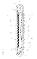
- Fig. 1 The arrangement according to the invention shown in Fig. 1 is largely comparable to the arrangement shown in Fig. 5a / 5b.
- a worker's belt 2 which runs over rollers (drums) 4, 6, of which a roller 4 also serves as a drive roller.
- the worker's belt 2 is supported by a sliding table 8.
- An essential difference to the two conventional arrangements (Fig. 4/5) is that the worker's band 2 according to the invention serves in any way as a sliding belt.
- a wear belt 20 extends over the entire width. This wear belt 20 is formed as well as the slide belt 2 endless and is on the rollers 24a, 24b, ... endangered.
- the length of the wear belt 20 deviates from the length of the worker's belt (sliding belt) 2. This has the consequence that with each revolution, a respective changing portion of the wear belt 20 faces the underside of the worker's belt 2. Thus, in particular, the load points in the area of the wheel contact surfaces change.
- the lower run 2b of the worker's belt 2 is - as well as the lower run 20b of the wear belt - by rollers 22a, 22b, ... supported.
- the up and down zones are provided with roller support, ie the space between the drive roller 4 and tension roller 6 on the one hand and wear belt 20 on the other hand is also filled with support rollers 26.
- FIG. 2 shows except upper run 2a and Untertrum 2b a worker's belt 2 in addition to carrying rollers 22a, 22b, ... also a slide belt 20a / 20b.
- the upper run 20a of this slide belt is supported by a slide table 8.
- the slide table 8 has side rails 8a, 8b. These Sidebars 8a, 8b serve for the lateral guide boundary of the worker's band 2 and Wear belt 20.
Landscapes
- Engineering & Computer Science (AREA)
- Manufacturing & Machinery (AREA)
- Chemical & Material Sciences (AREA)
- Combustion & Propulsion (AREA)
- Transportation (AREA)
- Mechanical Engineering (AREA)
- Belt Conveyors (AREA)
- Forklifts And Lifting Vehicles (AREA)
- Handcart (AREA)
- Escalators And Moving Walkways (AREA)
- Structure Of Belt Conveyors (AREA)
Abstract
Description
Zusammenfassend ist festzuhalten: Die punktuell erhöhte Friktion zwischen Werkerband (Gleitgurt) und Gleittisch tritt vorzugsweise bei Gurten mit fest vorgegebenen Belastungspunkten insbesondere "Radstoppern" auf. Durch diese Radstopper sind die jeweiligen Radstandsflächen festgelegt. Je stärker (häufiger oder höher) die Belastung, desto früher der Ausfall durch vorzeitiges Durchscheuern der Gleitlage des gegenüber dem jeweils ortsfesten Gleitboden vorwärtsbewegten Gleitgurtes.
Da die als Verschleißgurte ausgebildeten Gleitgurte üblicherweise lediglich die Breite der Aufstandsflächen aufweisen (siehe Fig. 3b), muss das Werkerband (der Hauptgurt) ebenfalls mit einer Verschleißlage versehen sein, denn ein Großteil des Werkerbandes gleitet ebenfalls auf dem Gleittisch entlang. Auch wenn beim Hauptgurt die Abnutzung durch Reibung auf dem Gleittisch nicht so groß ist, wie bei dem durch Aufstandsflächen belasteten Verschleißgurt, so ergibt sich auch beim Hauptgurt ein vorzeitiger Verschleiß aufgrund des Gleitens auf der Unterlage. Dies ist aus mehreren Gründen unerwünscht:
Der Hauptgurt stellt einen beträchtlichen Kostenanteil an einer Werkerbandanlage dar, so dass seine Erneuerung unter Wirtschaftlichkeitsgesichtspunkten keinesfalls vernachlässigbar gering ist. Außerdem ist das Auswechseln des gesamten Hauptgurtes sehr zeitaufwendig. D. h.: Die mit der Werkerbandanlage laufende Kfz-Fertigung muss für längere Zeit unterbrochen werden.
Zudem werden in der praktischen Anwendung teilweise Antriebstrommeln mit keramischer Beschichtung eingesetzt. Durch die höhere Antriebsleistung der keramischen Trommel wird die mechanische Belastung der Trommellager, Getriebe und Motoren reduziert. Dieser harte Werkstoff wirkt ebenfalls lebensdauerverkürzend auf die Gleitlage des Werkerbandes und damit lebensdauerverkürzend auf das gesamte Werkerband (Hauptgurt, Transportband).
Da auf eine Gleitoberfläche auf der Basis textilen Materials bewusst verzichtet werden kann, ist es nun auch erstmals möglich, insbesondere die laufseitige Oberfläche mit einer beliebigen Struktur (z. B. einem Profil) zu versehen. Damit ist eine weitere Verbesserung der Griffigkeit gegenüber dem Verschleißgurt gegeben. Auf einen separaten Antrieb für den Verschleißgurt kann deshalb verzichtet werden.
Anstelle von zwischen Gleittisch und Trommeln einzufügenden Gleitleisten können ebenfalls Rollen angebracht werden.
An dem Gleittisch angebrachte Seitenleisten sorgen für eine zuverlässige Längsführungsbegrenzung der beiden Gurte.
Während des Betriebs gleitet das Werkerband (der Gleitgurt) 102 über die Gleittische 108, 110. Wegen der punktuellen Belastung unter den Rädern 116a, 116b, ... kommt es an den Belastungspunkten zu erhöhtem Verschleiß. Dadurch ist die Lebensdauer herkömmlicher Werkerbänder 102 stark eingeschränkt.
Wie aus der Betrachtung in Fahrtrichtung (Fig. 5b) zu entnehmen, ist der Gleitgurt 220 (Fig. 5a) zweiteilig, wovon jeder Teilgurt 220a bzw. 220b jeweils eine Spur (Radaufstandsfläche 218) der zu bearbeitenden, ein- bis n-spurigen Fahrzeuge 214a, ... bzw. Transportgegenstände unterstützt. Bezüglich der restlichen Breite gleitet das Werkerband 202 direkt auf dem Gleittisch 208 entlang. Aus diesem Grunde ist das Werkerband 202 - ebenso wie der Verschleißgurt 220 bzw. die Verschleißgurte 22a, 220b - laufseitig mit einer Gleitlage 202a aus textilem Material versehen.
Ein wesentlicher Unterschied zu den beiden herkömmlichen Anordnungen (Fig. 4/5) besteht darin, dass das erfindungsgemäße Werkerband 2 in keiner Weise als Gleitgurt dient. Zwischen Werkerband 2 und Gleittisch 8 erstreckt sich über die gesamter Breite ein Verschleißgurt 20.
Dieser Verschleißgurt 20 ist ebenso wie der Gleitgurt 2 endlos ausgebildet und wird über die Rollen 24a, 24b, ... gefährt.
Die Länge des Verschleißgurtes 20 weicht von der Länge des Werkerbandes (Gleitgurtes) 2 ab. Dies hat zur Folge, dass bei jedem Umlauf ein jeweils wechselnder Abschnitt des Verschleißgurtes 20 der Unterseite des Werkerbandes 2 gegenübersteht. Damit wechseln insbesondere auch die Belastungspunkte im Bereich der Radaufstandsflächen.
Das Untertrum 2b des Werkerbandes 2 wird - ebenso wie das Untertrum 20b des Verschleißgurtes - durch Rollen 22a, 22b, ... abgestützt.
Am Obertrum 2a sind die Auf- und Ablaufzonen mit Rollenunterstützung versehen, d. h. der Zwischenraum zwischen Antriebsrolle 4 und Spannrolle 6 einerseits und Verschleißgurt 20 andererseits ist ebenfalls mit Tragrollen 26 ausgefüllt.
- 102
- Werkerband (Gleitgurt)
- 104, 106
- Rollen, Trommeln (für Werkerband)
- 104
- Antriebsrolle, Antriebstrommel (für Werkerband)
- 106
- Spanntrommel (für Werkerband)
- 108, 110
- Gleittisch(e)
- 112a, 112b, ...
- Radstopper
- 114a, 114b, ...
- Personenkraftwagen, Fahrzeug(e)
- 116a,116b, ...
- Räder
- 128
- Haftgummi
- 130
- Zugträgerseile, Stahlseile
- 132a, 132b
- (Stahlcord-)Querverstärkung
- 134
- Deckplatte
- 136
- (Polyester-)Gleitgewebelage
- 13 8a, 13 8b
- Querverstärkung
- 140
- Zwischenschicht
- 142
- Vollgummikante
- 202
- Werkerband
- 202a
- Gleitlage
- 204, 206
- Rollen, Trommeln (für Werkerband)
- 204
- Antriebsrolle, Antriebstrommel (für Werkerband)
- 206
- Spanntrommel (für Werkerband)
- 208
- Gleittisch
- 212a, ...
- Radstopper
- 214a
- Personenkraftwagen, Fahrzeug
- 216a, ...
- Räder
- 218
- Radaufstandsfläche
- 220; 220a, 220b
- Verschleißgurt
- 222a, 222b, ...
- Rollen
- 2
- Werkerband, Hauptgurt
- 2a
- Obertrum des Werkerbandes, ... des Hauptgurtes
- 2b
- Untertrum des Werkerbandes, ... des Hauptgurtes
- 4,6
- Rollen, Trommeln
- 4
- Antriebsrolle, Antriebstrommel
- 6
- Spanntrommel
- 8
- Gleittisch
- 8a, 8b
- Seitenleisten
- 20
- Verschleißgurt, Verschleißband
- 20a
- Obertrum des Verschleißgurtes
- 20b
- Untertrum des Verschleißgurtes
- 22a, 22b, ...
- Tragrollen des Werkerbandes
- 24a, 24b, ...
- Tragrollen des Verschleißgurtes
- 26
- Tragrollen
- 28
- laufseitige Struktur am Werkerband, ... Hauptgurt
- 30
- Gleitlagengewebe des Verschleißgurtes
- AA'
- Querschnitt durch eine Werkerbandanordnung
Claims (7)
- Montageanordnung mit mindestens einem endlosen, als "Werkerband" dienenden Hauptgurt (2),dadurch gekennzeichnet,der zwischen einer Antriebstrommel (4) und einer Spanntrommel (6) auf mindestens einem ortsfesten Gleittisch (8, ...) abläuft, und
wobei zwischen Hauptgurt (2) und dem mindestens einen Gleittisch (8, ...) mindestens ein mit der Geschwindigkeit des Hauptgurtes (2) mitlaufender, endloser Verschleißgurt (20, ...) angeordnet ist,dass im Fall eines einzigen Verschleißgurtes (20) und eines einzigen Gleittisches (8) dieser Verschleißgurt (20) mindestens so breit ist wie der Gleittisch (8),dass im Fall eines einzigen Verschleißgurtes (20) und mehrerer Gleittische (8, ...) dieser Verschleißgurt (20) mindestens so breit ist wie der breiteste der Gleittische (8, ...),dass im Fall mehrerer Verschleißgurte (20, ...) und mehrerer Gleittische (8, ...) der schmalste der Verschleißgurte (20, ...) mindestens so breit ist wie der breiteste der Gleittische (8, ...), und/oderdass im Fall eines einzigen Verschleißgurtes (20) der Hauptgurt (2) höchstens so breit ist wie der Verschleißgurt (20), wobei sich die Breite des Verschleißgurtes (20) über die gesamte Breite des Hauptgurtes (2) erstreckt, bzw. bei mehreren Verschleißgurten (20, ...):dass der Hauptgurt (2) höchstens so breit ist wie der schmalste der Verschleißgurte (20, ...), wobei sich die Breite des schmalsten der Verschleißgurte (20, ...) über die gesamte Breite des Hauptgurtes (2) erstreckt. - Montageanordnung nach Anspruch1,
dadurch gekennzeichnet, dass ein über die Breite des mindestens einen Verschleißgurtes (20, ...) und über die Breite des mindestens einen Gleittisches (8, ...) hinausragender Bereich des Hauptgurtes (2) durch Tragrollen abgestützt oder durch Trittleisten abgedeckt ist. - Montageanordnung nach Anspruch 1 oder 2,
dadurch gekennzeichnet, dass zwischen dem trommelseitigen Ende des mindestens einen Verschleißgurtes (20, ...) und der benachbarten Trommel (4) und/oder (6) mindestens eine Tragrolle (26, ...) angeordnet ist. - Montageanordnung nach einem der Ansprüche 1 bis 3,
dadurch gekennzeichnet, dass der Hauptgurt (2) laufseitig keine Gleitlage aufweist. - Montageanordnung nach einem der Ansprüche 1 bis 4,
dadurch gekennzeichnet, dass die laufseitige Oberfläche des Hauptgurtes (2) mit einer profilartigen Struktur versehen ist. - Montageanordnung nach einem der Ansprüche 1 bis 5,
dadurch gekennzeichnet, dass mindestens ein Gleittisch (8) seitlich angebrachte Leisten (8a, 8b) aufweist. - Montageanordnung nach einem der Ansprüche 1 bis 6,
dadurch gekennzeichnet, dass Antriebstrommel (4) und/oder Spanntrommel (6) eine keramische Beschichtung aufweisen.
Priority Applications (1)
| Application Number | Priority Date | Filing Date | Title |
|---|---|---|---|
| PL04106380T PL1557347T3 (pl) | 2004-01-20 | 2004-12-08 | Układ montażowy dla samochodów z poruszającą się po nieruchomym stole poślizgowym „taśmą montażową” względnie taśmą poślizgową |
Applications Claiming Priority (2)
| Application Number | Priority Date | Filing Date | Title |
|---|---|---|---|
| DE102004002750A DE102004002750A1 (de) | 2004-01-20 | 2004-01-20 | Montageanordnung mit "Werkerband" und Gleittisch |
| DE102004002750 | 2004-01-20 |
Publications (3)
| Publication Number | Publication Date |
|---|---|
| EP1557347A2 true EP1557347A2 (de) | 2005-07-27 |
| EP1557347A3 EP1557347A3 (de) | 2005-11-16 |
| EP1557347B1 EP1557347B1 (de) | 2008-03-05 |
Family
ID=34625718
Family Applications (1)
| Application Number | Title | Priority Date | Filing Date |
|---|---|---|---|
| EP04106380A Expired - Lifetime EP1557347B1 (de) | 2004-01-20 | 2004-12-08 | Montageanordnung für Kraftwagen mit einem auf einem ortsfesten Gleittisch laufenden "Werkerband" bzw. Gleitgurt. |
Country Status (5)
| Country | Link |
|---|---|
| EP (1) | EP1557347B1 (de) |
| AT (1) | ATE388076T1 (de) |
| DE (2) | DE102004002750A1 (de) |
| ES (1) | ES2301941T3 (de) |
| PL (1) | PL1557347T3 (de) |
Families Citing this family (1)
| Publication number | Priority date | Publication date | Assignee | Title |
|---|---|---|---|---|
| DE102023106278A1 (de) * | 2023-03-14 | 2024-09-19 | Multivac Sepp Haggenmüller Se & Co. Kg | Bandfördervorrichtung mit Führungselementen |
Citations (1)
| Publication number | Priority date | Publication date | Assignee | Title |
|---|---|---|---|---|
| DE10062465A1 (de) | 2000-12-14 | 2002-06-20 | Contitech Transportbandsysteme | Montageanordnung mit "Werkerband" für die Endbearbeitung von bereits vormontierten Personenkraftwagen |
Family Cites Families (3)
| Publication number | Priority date | Publication date | Assignee | Title |
|---|---|---|---|---|
| US5411279A (en) * | 1993-12-17 | 1995-05-02 | Magid; Sidney H. | Multiple-belt conveying apparatus with flat top surface |
| DE10017159A1 (de) * | 2000-04-06 | 2001-10-11 | Schlafhorst Gpt Gmbh Ges Fuer | Fördereinrichtung |
| DE20208385U1 (de) * | 2001-05-30 | 2002-08-29 | Dreier, Erich, Kleinlützel | Förderanlage |
-
2004
- 2004-01-20 DE DE102004002750A patent/DE102004002750A1/de not_active Withdrawn
- 2004-12-08 DE DE502004006405T patent/DE502004006405D1/de not_active Expired - Lifetime
- 2004-12-08 PL PL04106380T patent/PL1557347T3/pl unknown
- 2004-12-08 ES ES04106380T patent/ES2301941T3/es not_active Expired - Lifetime
- 2004-12-08 EP EP04106380A patent/EP1557347B1/de not_active Expired - Lifetime
- 2004-12-08 AT AT04106380T patent/ATE388076T1/de not_active IP Right Cessation
Patent Citations (1)
| Publication number | Priority date | Publication date | Assignee | Title |
|---|---|---|---|---|
| DE10062465A1 (de) | 2000-12-14 | 2002-06-20 | Contitech Transportbandsysteme | Montageanordnung mit "Werkerband" für die Endbearbeitung von bereits vormontierten Personenkraftwagen |
Also Published As
| Publication number | Publication date |
|---|---|
| EP1557347B1 (de) | 2008-03-05 |
| ES2301941T3 (es) | 2008-07-01 |
| DE102004002750A1 (de) | 2005-08-04 |
| DE502004006405D1 (de) | 2008-04-17 |
| PL1557347T3 (pl) | 2008-08-29 |
| EP1557347A3 (de) | 2005-11-16 |
| ATE388076T1 (de) | 2008-03-15 |
Similar Documents
| Publication | Publication Date | Title |
|---|---|---|
| EP3078543B1 (de) | Fahrzeug zum transport von schütt- und/oder stückgut | |
| EP0672013B1 (de) | Antriebs- und führungseinrichtung für stetigförderer | |
| EP0541850B1 (de) | Kurvengängiges Plattenband | |
| EP2265521B1 (de) | Förderband für eine langstreckenförderanlage mit sich längs erstreckenden seitenwänden | |
| WO2018077670A1 (de) | Fördersystem | |
| EP0304543B1 (de) | Hängeförderer | |
| EP2019055B1 (de) | Lagereinheit für eine Förderanlage zum Transport von Gütern mittels eines Förderbandes | |
| AT394024B (de) | Rollen innerhalb einer transportkette einer personenfoerdereinrichtung und anordnung | |
| EP2039628A2 (de) | Förderanlage zum Transport von Gütern | |
| EP0880462B1 (de) | Kurvenbandförderer | |
| EP1557347B1 (de) | Montageanordnung für Kraftwagen mit einem auf einem ortsfesten Gleittisch laufenden "Werkerband" bzw. Gleitgurt. | |
| DE19917368C2 (de) | Stetigförderer | |
| DE112005000182B4 (de) | Umlenkeinrichtungsführung zum Halten eines sich über eine Umlenkeinrichtung bewegenden Handlaufs | |
| EP2030920B1 (de) | Bandförderer | |
| DE112009004904B4 (de) | Antriebsanordnung für eine Personenbeförderungsvorrichtung | |
| EP1059214B1 (de) | Beförderungseinheit | |
| EP1443012B1 (de) | Fahrtreppe oder Fahrsteig | |
| EP1215110B1 (de) | Montageanordnung mit "Förderband" für die Endbearbeitung von bereits vormontierten Personenkraftwagen | |
| DE19844304C1 (de) | Kettenförderer für Transportgut | |
| DE102004009842B4 (de) | Staurollenförderer | |
| EP2264245B1 (de) | Einbaufertiger | |
| EP1142805B1 (de) | Fördereinrichtung | |
| DE102005024434B4 (de) | Kurvenförderer mit endlosem Fördergurt zum Fördern von Stückgut | |
| DE19832637A1 (de) | Raupenfahrwerk | |
| DE102023131012A1 (de) | Kanalfahrzeug und Regalbediensystem mit einem solchen |
Legal Events
| Date | Code | Title | Description |
|---|---|---|---|
| PUAI | Public reference made under article 153(3) epc to a published international application that has entered the european phase |
Free format text: ORIGINAL CODE: 0009012 |
|
| AK | Designated contracting states |
Kind code of ref document: A2 Designated state(s): AT BE BG CH CY CZ DE DK EE ES FI FR GB GR HU IE IS IT LI LT LU MC NL PL PT RO SE SI SK TR |
|
| AX | Request for extension of the european patent |
Extension state: AL BA HR LV MK YU |
|
| PUAL | Search report despatched |
Free format text: ORIGINAL CODE: 0009013 |
|
| AK | Designated contracting states |
Kind code of ref document: A3 Designated state(s): AT BE BG CH CY CZ DE DK EE ES FI FR GB GR HU IE IS IT LI LT LU MC NL PL PT RO SE SI SK TR |
|
| AX | Request for extension of the european patent |
Extension state: AL BA HR LV MK YU |
|
| 17P | Request for examination filed |
Effective date: 20060516 |
|
| AKX | Designation fees paid |
Designated state(s): AT BE BG CH CY CZ DE DK EE ES FI FR GB GR HU IE IS IT LI LT LU MC NL PL PT RO SE SI SK TR |
|
| 17Q | First examination report despatched |
Effective date: 20061220 |
|
| GRAP | Despatch of communication of intention to grant a patent |
Free format text: ORIGINAL CODE: EPIDOSNIGR1 |
|
| GRAS | Grant fee paid |
Free format text: ORIGINAL CODE: EPIDOSNIGR3 |
|
| GRAA | (expected) grant |
Free format text: ORIGINAL CODE: 0009210 |
|
| AK | Designated contracting states |
Kind code of ref document: B1 Designated state(s): AT BE BG CH CY CZ DE DK EE ES FI FR GB GR HU IE IS IT LI LT LU MC NL PL PT RO SE SI SK TR |
|
| REG | Reference to a national code |
Ref country code: GB Ref legal event code: FG4D Free format text: NOT ENGLISH |
|
| REG | Reference to a national code |
Ref country code: CH Ref legal event code: EP |
|
| REG | Reference to a national code |
Ref country code: IE Ref legal event code: FG4D Free format text: LANGUAGE OF EP DOCUMENT: GERMAN |
|
| REF | Corresponds to: |
Ref document number: 502004006405 Country of ref document: DE Date of ref document: 20080417 Kind code of ref document: P |
|
| REG | Reference to a national code |
Ref country code: SE Ref legal event code: TRGR |
|
| REG | Reference to a national code |
Ref country code: ES Ref legal event code: FG2A Ref document number: 2301941 Country of ref document: ES Kind code of ref document: T3 |
|
| PG25 | Lapsed in a contracting state [announced via postgrant information from national office to epo] |
Ref country code: FI Free format text: LAPSE BECAUSE OF FAILURE TO SUBMIT A TRANSLATION OF THE DESCRIPTION OR TO PAY THE FEE WITHIN THE PRESCRIBED TIME-LIMIT Effective date: 20080305 |
|
| REG | Reference to a national code |
Ref country code: PL Ref legal event code: T3 |
|
| NLV1 | Nl: lapsed or annulled due to failure to fulfill the requirements of art. 29p and 29m of the patents act | ||
| PG25 | Lapsed in a contracting state [announced via postgrant information from national office to epo] |
Ref country code: SI Free format text: LAPSE BECAUSE OF FAILURE TO SUBMIT A TRANSLATION OF THE DESCRIPTION OR TO PAY THE FEE WITHIN THE PRESCRIBED TIME-LIMIT Effective date: 20080305 |
|
| REG | Reference to a national code |
Ref country code: IE Ref legal event code: FD4D |
|
| PG25 | Lapsed in a contracting state [announced via postgrant information from national office to epo] |
Ref country code: PT Free format text: LAPSE BECAUSE OF FAILURE TO SUBMIT A TRANSLATION OF THE DESCRIPTION OR TO PAY THE FEE WITHIN THE PRESCRIBED TIME-LIMIT Effective date: 20080805 Ref country code: NL Free format text: LAPSE BECAUSE OF FAILURE TO SUBMIT A TRANSLATION OF THE DESCRIPTION OR TO PAY THE FEE WITHIN THE PRESCRIBED TIME-LIMIT Effective date: 20080305 |
|
| ET | Fr: translation filed | ||
| PG25 | Lapsed in a contracting state [announced via postgrant information from national office to epo] |
Ref country code: RO Free format text: LAPSE BECAUSE OF FAILURE TO SUBMIT A TRANSLATION OF THE DESCRIPTION OR TO PAY THE FEE WITHIN THE PRESCRIBED TIME-LIMIT Effective date: 20080305 |
|
| PG25 | Lapsed in a contracting state [announced via postgrant information from national office to epo] |
Ref country code: IS Free format text: LAPSE BECAUSE OF FAILURE TO SUBMIT A TRANSLATION OF THE DESCRIPTION OR TO PAY THE FEE WITHIN THE PRESCRIBED TIME-LIMIT Effective date: 20080705 |
|
| PLBE | No opposition filed within time limit |
Free format text: ORIGINAL CODE: 0009261 |
|
| STAA | Information on the status of an ep patent application or granted ep patent |
Free format text: STATUS: NO OPPOSITION FILED WITHIN TIME LIMIT |
|
| PG25 | Lapsed in a contracting state [announced via postgrant information from national office to epo] |
Ref country code: LT Free format text: LAPSE BECAUSE OF FAILURE TO SUBMIT A TRANSLATION OF THE DESCRIPTION OR TO PAY THE FEE WITHIN THE PRESCRIBED TIME-LIMIT Effective date: 20080305 Ref country code: IE Free format text: LAPSE BECAUSE OF FAILURE TO SUBMIT A TRANSLATION OF THE DESCRIPTION OR TO PAY THE FEE WITHIN THE PRESCRIBED TIME-LIMIT Effective date: 20080305 Ref country code: DK Free format text: LAPSE BECAUSE OF FAILURE TO SUBMIT A TRANSLATION OF THE DESCRIPTION OR TO PAY THE FEE WITHIN THE PRESCRIBED TIME-LIMIT Effective date: 20080305 |
|
| 26N | No opposition filed |
Effective date: 20081208 |
|
| PG25 | Lapsed in a contracting state [announced via postgrant information from national office to epo] |
Ref country code: BG Free format text: LAPSE BECAUSE OF FAILURE TO SUBMIT A TRANSLATION OF THE DESCRIPTION OR TO PAY THE FEE WITHIN THE PRESCRIBED TIME-LIMIT Effective date: 20080605 Ref country code: EE Free format text: LAPSE BECAUSE OF FAILURE TO SUBMIT A TRANSLATION OF THE DESCRIPTION OR TO PAY THE FEE WITHIN THE PRESCRIBED TIME-LIMIT Effective date: 20080305 |
|
| PG25 | Lapsed in a contracting state [announced via postgrant information from national office to epo] |
Ref country code: MC Free format text: LAPSE BECAUSE OF NON-PAYMENT OF DUE FEES Effective date: 20081231 |
|
| REG | Reference to a national code |
Ref country code: CH Ref legal event code: PL |
|
| PG25 | Lapsed in a contracting state [announced via postgrant information from national office to epo] |
Ref country code: CY Free format text: LAPSE BECAUSE OF FAILURE TO SUBMIT A TRANSLATION OF THE DESCRIPTION OR TO PAY THE FEE WITHIN THE PRESCRIBED TIME-LIMIT Effective date: 20080305 |
|
| PG25 | Lapsed in a contracting state [announced via postgrant information from national office to epo] |
Ref country code: CH Free format text: LAPSE BECAUSE OF NON-PAYMENT OF DUE FEES Effective date: 20081231 Ref country code: LI Free format text: LAPSE BECAUSE OF NON-PAYMENT OF DUE FEES Effective date: 20081231 |
|
| PGFP | Annual fee paid to national office [announced via postgrant information from national office to epo] |
Ref country code: AT Payment date: 20091217 Year of fee payment: 6 Ref country code: CZ Payment date: 20091207 Year of fee payment: 6 Ref country code: ES Payment date: 20091222 Year of fee payment: 6 Ref country code: SE Payment date: 20091214 Year of fee payment: 6 |
|
| PGFP | Annual fee paid to national office [announced via postgrant information from national office to epo] |
Ref country code: PL Payment date: 20091123 Year of fee payment: 6 Ref country code: SK Payment date: 20091208 Year of fee payment: 6 |
|
| PGFP | Annual fee paid to national office [announced via postgrant information from national office to epo] |
Ref country code: FR Payment date: 20100108 Year of fee payment: 6 Ref country code: GB Payment date: 20091218 Year of fee payment: 6 Ref country code: IT Payment date: 20091221 Year of fee payment: 6 |
|
| PGFP | Annual fee paid to national office [announced via postgrant information from national office to epo] |
Ref country code: BE Payment date: 20100212 Year of fee payment: 6 Ref country code: DE Payment date: 20091124 Year of fee payment: 6 |
|
| PG25 | Lapsed in a contracting state [announced via postgrant information from national office to epo] |
Ref country code: HU Free format text: LAPSE BECAUSE OF FAILURE TO SUBMIT A TRANSLATION OF THE DESCRIPTION OR TO PAY THE FEE WITHIN THE PRESCRIBED TIME-LIMIT Effective date: 20080906 Ref country code: LU Free format text: LAPSE BECAUSE OF NON-PAYMENT OF DUE FEES Effective date: 20081208 |
|
| PG25 | Lapsed in a contracting state [announced via postgrant information from national office to epo] |
Ref country code: TR Free format text: LAPSE BECAUSE OF FAILURE TO SUBMIT A TRANSLATION OF THE DESCRIPTION OR TO PAY THE FEE WITHIN THE PRESCRIBED TIME-LIMIT Effective date: 20080305 |
|
| PG25 | Lapsed in a contracting state [announced via postgrant information from national office to epo] |
Ref country code: GR Free format text: LAPSE BECAUSE OF FAILURE TO SUBMIT A TRANSLATION OF THE DESCRIPTION OR TO PAY THE FEE WITHIN THE PRESCRIBED TIME-LIMIT Effective date: 20080606 |
|
| BERE | Be: lapsed |
Owner name: CONTITECH TRANSPORTBANDSYSTEME G.M.B.H. Effective date: 20101231 |
|
| PG25 | Lapsed in a contracting state [announced via postgrant information from national office to epo] |
Ref country code: CZ Free format text: LAPSE BECAUSE OF NON-PAYMENT OF DUE FEES Effective date: 20101208 |
|
| GBPC | Gb: european patent ceased through non-payment of renewal fee |
Effective date: 20101208 |
|
| PG25 | Lapsed in a contracting state [announced via postgrant information from national office to epo] |
Ref country code: AT Free format text: LAPSE BECAUSE OF NON-PAYMENT OF DUE FEES Effective date: 20101208 |
|
| REG | Reference to a national code |
Ref country code: SK Ref legal event code: MM4A Ref document number: E 3467 Country of ref document: SK Effective date: 20101208 |
|
| REG | Reference to a national code |
Ref country code: FR Ref legal event code: ST Effective date: 20110831 |
|
| REG | Reference to a national code |
Ref country code: SE Ref legal event code: EUG |
|
| PG25 | Lapsed in a contracting state [announced via postgrant information from national office to epo] |
Ref country code: SE Free format text: LAPSE BECAUSE OF NON-PAYMENT OF DUE FEES Effective date: 20101209 Ref country code: BE Free format text: LAPSE BECAUSE OF NON-PAYMENT OF DUE FEES Effective date: 20101231 |
|
| PG25 | Lapsed in a contracting state [announced via postgrant information from national office to epo] |
Ref country code: FR Free format text: LAPSE BECAUSE OF NON-PAYMENT OF DUE FEES Effective date: 20110103 |
|
| REG | Reference to a national code |
Ref country code: DE Ref legal event code: R119 Ref document number: 502004006405 Country of ref document: DE Effective date: 20110701 |
|
| PG25 | Lapsed in a contracting state [announced via postgrant information from national office to epo] |
Ref country code: GB Free format text: LAPSE BECAUSE OF NON-PAYMENT OF DUE FEES Effective date: 20101208 Ref country code: SK Free format text: LAPSE BECAUSE OF NON-PAYMENT OF DUE FEES Effective date: 20101208 Ref country code: DE Free format text: LAPSE BECAUSE OF NON-PAYMENT OF DUE FEES Effective date: 20110701 |
|
| PG25 | Lapsed in a contracting state [announced via postgrant information from national office to epo] |
Ref country code: IT Free format text: LAPSE BECAUSE OF NON-PAYMENT OF DUE FEES Effective date: 20101208 |
|
| REG | Reference to a national code |
Ref country code: ES Ref legal event code: FD2A Effective date: 20120206 |
|
| PG25 | Lapsed in a contracting state [announced via postgrant information from national office to epo] |
Ref country code: ES Free format text: LAPSE BECAUSE OF NON-PAYMENT OF DUE FEES Effective date: 20101209 |
|
| REG | Reference to a national code |
Ref country code: PL Ref legal event code: LAPE |
|
| PG25 | Lapsed in a contracting state [announced via postgrant information from national office to epo] |
Ref country code: PL Free format text: LAPSE BECAUSE OF NON-PAYMENT OF DUE FEES Effective date: 20101208 |