EP1557367A1 - Structure formant un dispositif de levage, et contenant pour produits chimiques dote de ladite structure - Google Patents
Structure formant un dispositif de levage, et contenant pour produits chimiques dote de ladite structure Download PDFInfo
- Publication number
- EP1557367A1 EP1557367A1 EP03748576A EP03748576A EP1557367A1 EP 1557367 A1 EP1557367 A1 EP 1557367A1 EP 03748576 A EP03748576 A EP 03748576A EP 03748576 A EP03748576 A EP 03748576A EP 1557367 A1 EP1557367 A1 EP 1557367A1
- Authority
- EP
- European Patent Office
- Prior art keywords
- suspender
- film
- forming
- strip
- support ring
- Prior art date
- Legal status (The legal status is an assumption and is not a legal conclusion. Google has not performed a legal analysis and makes no representation as to the accuracy of the status listed.)
- Withdrawn
Links
Images


Classifications
-
- B—PERFORMING OPERATIONS; TRANSPORTING
- B65—CONVEYING; PACKING; STORING; HANDLING THIN OR FILAMENTARY MATERIAL
- B65D—CONTAINERS FOR STORAGE OR TRANSPORT OF ARTICLES OR MATERIALS, e.g. BAGS, BARRELS, BOTTLES, BOXES, CANS, CARTONS, CRATES, DRUMS, JARS, TANKS, HOPPERS, FORWARDING CONTAINERS; ACCESSORIES, CLOSURES, OR FITTINGS THEREFOR; PACKAGING ELEMENTS; PACKAGES
- B65D25/00—Details of other kinds or types of rigid or semi-rigid containers
- B65D25/20—External fittings
-
- A—HUMAN NECESSITIES
- A61—MEDICAL OR VETERINARY SCIENCE; HYGIENE
- A61J—CONTAINERS SPECIALLY ADAPTED FOR MEDICAL OR PHARMACEUTICAL PURPOSES; DEVICES OR METHODS SPECIALLY ADAPTED FOR BRINGING PHARMACEUTICAL PRODUCTS INTO PARTICULAR PHYSICAL OR ADMINISTERING FORMS; DEVICES FOR ADMINISTERING FOOD OR MEDICINES ORALLY; BABY COMFORTERS; DEVICES FOR RECEIVING SPITTLE
- A61J1/00—Containers specially adapted for medical or pharmaceutical purposes
- A61J1/14—Details; Accessories therefor
- A61J1/20—Arrangements for transferring or mixing fluids, e.g. from vial to syringe
- A61J1/2089—Containers or vials which are to be joined to each other in order to mix their contents
-
- B—PERFORMING OPERATIONS; TRANSPORTING
- B65—CONVEYING; PACKING; STORING; HANDLING THIN OR FILAMENTARY MATERIAL
- B65D—CONTAINERS FOR STORAGE OR TRANSPORT OF ARTICLES OR MATERIALS, e.g. BAGS, BARRELS, BOTTLES, BOXES, CANS, CARTONS, CRATES, DRUMS, JARS, TANKS, HOPPERS, FORWARDING CONTAINERS; ACCESSORIES, CLOSURES, OR FITTINGS THEREFOR; PACKAGING ELEMENTS; PACKAGES
- B65D23/00—Details of bottles or jars not otherwise provided for
- B65D23/003—Suspension means
- B65D23/005—Suspension means in the form of a label hanger
-
- B—PERFORMING OPERATIONS; TRANSPORTING
- B65—CONVEYING; PACKING; STORING; HANDLING THIN OR FILAMENTARY MATERIAL
- B65D—CONTAINERS FOR STORAGE OR TRANSPORT OF ARTICLES OR MATERIALS, e.g. BAGS, BARRELS, BOTTLES, BOXES, CANS, CARTONS, CRATES, DRUMS, JARS, TANKS, HOPPERS, FORWARDING CONTAINERS; ACCESSORIES, CLOSURES, OR FITTINGS THEREFOR; PACKAGING ELEMENTS; PACKAGES
- B65D25/00—Details of other kinds or types of rigid or semi-rigid containers
- B65D25/20—External fittings
- B65D25/22—External fittings for facilitating lifting or suspending of containers
-
- B—PERFORMING OPERATIONS; TRANSPORTING
- B65—CONVEYING; PACKING; STORING; HANDLING THIN OR FILAMENTARY MATERIAL
- B65D—CONTAINERS FOR STORAGE OR TRANSPORT OF ARTICLES OR MATERIALS, e.g. BAGS, BARRELS, BOTTLES, BOXES, CANS, CARTONS, CRATES, DRUMS, JARS, TANKS, HOPPERS, FORWARDING CONTAINERS; ACCESSORIES, CLOSURES, OR FITTINGS THEREFOR; PACKAGING ELEMENTS; PACKAGES
- B65D25/00—Details of other kinds or types of rigid or semi-rigid containers
- B65D25/28—Handles
- B65D25/2867—Handles with respective ends fixed to local areas of two opposite sides or wall-part
- B65D25/2873—Straps or slings
-
- B—PERFORMING OPERATIONS; TRANSPORTING
- B65—CONVEYING; PACKING; STORING; HANDLING THIN OR FILAMENTARY MATERIAL
- B65D—CONTAINERS FOR STORAGE OR TRANSPORT OF ARTICLES OR MATERIALS, e.g. BAGS, BARRELS, BOTTLES, BOXES, CANS, CARTONS, CRATES, DRUMS, JARS, TANKS, HOPPERS, FORWARDING CONTAINERS; ACCESSORIES, CLOSURES, OR FITTINGS THEREFOR; PACKAGING ELEMENTS; PACKAGES
- B65D51/00—Closures not otherwise provided for
- B65D51/24—Closures not otherwise provided for combined or co-operating with auxiliary devices for non-closing purposes
- B65D51/28—Closures not otherwise provided for combined or co-operating with auxiliary devices for non-closing purposes with auxiliary containers for additional articles or materials
-
- B—PERFORMING OPERATIONS; TRANSPORTING
- B65—CONVEYING; PACKING; STORING; HANDLING THIN OR FILAMENTARY MATERIAL
- B65D—CONTAINERS FOR STORAGE OR TRANSPORT OF ARTICLES OR MATERIALS, e.g. BAGS, BARRELS, BOTTLES, BOXES, CANS, CARTONS, CRATES, DRUMS, JARS, TANKS, HOPPERS, FORWARDING CONTAINERS; ACCESSORIES, CLOSURES, OR FITTINGS THEREFOR; PACKAGING ELEMENTS; PACKAGES
- B65D55/00—Accessories for container closures not otherwise provided for
- B65D55/02—Locking devices; Means for discouraging or indicating unauthorised opening or removal of closure
- B65D55/06—Deformable or tearable wires, strings or strips; Use of seals
- B65D55/08—Annular elements encircling container necks
- B65D55/0818—Destructible or permanently removable bands, e.g. adhesive
- B65D55/0854—Shrink-film bands
-
- A—HUMAN NECESSITIES
- A61—MEDICAL OR VETERINARY SCIENCE; HYGIENE
- A61J—CONTAINERS SPECIALLY ADAPTED FOR MEDICAL OR PHARMACEUTICAL PURPOSES; DEVICES OR METHODS SPECIALLY ADAPTED FOR BRINGING PHARMACEUTICAL PRODUCTS INTO PARTICULAR PHYSICAL OR ADMINISTERING FORMS; DEVICES FOR ADMINISTERING FOOD OR MEDICINES ORALLY; BABY COMFORTERS; DEVICES FOR RECEIVING SPITTLE
- A61J1/00—Containers specially adapted for medical or pharmaceutical purposes
- A61J1/14—Details; Accessories therefor
- A61J1/20—Arrangements for transferring or mixing fluids, e.g. from vial to syringe
- A61J1/2003—Accessories used in combination with means for transfer or mixing of fluids, e.g. for activating fluid flow, separating fluids, filtering fluid or venting
- A61J1/2006—Piercing means
- A61J1/201—Piercing means having one piercing end
-
- A—HUMAN NECESSITIES
- A61—MEDICAL OR VETERINARY SCIENCE; HYGIENE
- A61J—CONTAINERS SPECIALLY ADAPTED FOR MEDICAL OR PHARMACEUTICAL PURPOSES; DEVICES OR METHODS SPECIALLY ADAPTED FOR BRINGING PHARMACEUTICAL PRODUCTS INTO PARTICULAR PHYSICAL OR ADMINISTERING FORMS; DEVICES FOR ADMINISTERING FOOD OR MEDICINES ORALLY; BABY COMFORTERS; DEVICES FOR RECEIVING SPITTLE
- A61J1/00—Containers specially adapted for medical or pharmaceutical purposes
- A61J1/14—Details; Accessories therefor
- A61J1/20—Arrangements for transferring or mixing fluids, e.g. from vial to syringe
- A61J1/2003—Accessories used in combination with means for transfer or mixing of fluids, e.g. for activating fluid flow, separating fluids, filtering fluid or venting
- A61J1/2006—Piercing means
- A61J1/2013—Piercing means having two piercing ends
Definitions
- the present invention relates to a structure for forming a suspender fixed to an article for suspending the article and to a medication container having the suspender-forming structure.
- suspender is attached to various articles for suspending the articles.
- these suspenders are in the form of a cord or a strip having a length required for suspending the article. They are attached at their one end or both ends to the article to be suspended.
- suspender generally a cord type suspender
- a suspender cord or the like is not attached to a single-use camera because the camera is packaged with a plastics film before use and because of increased costs.
- a case cover having a suspender cord was proposed, for example, in Japanese Unexamined Patent Publication No.Hei 6-269311.
- Containers for example, PET bottles, steel cans or aluminum cans containing health beverages, refreshing drinks, tea or the like need not always use a suspender.
- various types of suspenders to be attached to the containers in need have been proposed as in Japanese Utility Model Registrations Nos. 3041654; 3054989; and 3065786.
- a medication container for medical use having a certain kind of structure involves a difficulty in fixing a suspender to the container. This problem will be described with reference to drawings.
- Medication containers having various structures are available.
- Japanese Utility Model Publication Hei 4-No. 22745 discloses a medication container having a double-ended needle for mixing and injecting a medication in intravenous drip of injection drugs mainly such as antibiotics as shown in Fig.16 contained in small vials as shown in Fig.16.
- a medication container 1' of this kind has a container main body 2' made of plastic and deformable under compression.
- the container main body 2' has an opening 3a at an upper position.
- the opening 3a has a seal 4a sealed with an elastic material.
- the seal 4a is provided with a cylindrical support ring 5 upwardly extending to lie erect and removably fitted therein.
- the support ring 5 supports a double-ended needle 6 with a pair of needle points 6a, 6b formed at upper and lower ends and communicating with each other.
- the needle 6 is slidable upward and downward and is supported such that when the needle is moved downward, the lower needle point 6b pierces the seal 4a of the opening 3.
- the support ring 5 is covered with a protective cap 7.
- the support ring 5 and the protective cap 7 can be suitably removed by a screwed portion 7a.
- a joint between the support ring 5 and the protective cap 7 is covered with a shrink film 8 to guarantee that the cap is not opened yet.
- a perforation (not shown) is formed at the joint between the support ring 5 and the protective cap 7, a perforation (not shown) is formed.
- the view may be seen as if the shrink film 8 were separated from the support ring 5 and the protective cap 7, but actually it is closely contacted with them.
- the protective cap 7 under the shrink film 8 is held, and unscrewed in an unscrewing direction, the shrink film 8 is cut off at the perforation so that an upper portion of the film 8 above the perforation is removed along with the protective cap 7. (Fig. 17(A)).
- the upper needle point 6a is inserted into a sealed opening B1 of the vial B and the double-ended needle 6 is slided downward along the support ring 5 so that the lower needle point 6b is made to successively pierce the seal portion 4a, and a seal film 9a of an intermediate plug 9 to cause the vial B to internally communicate with the container main body 2'.
- the contents of the vial B and the container main body 2' are mingled together and the mixture is returned to the container main body 2' (Fig.17(B)). Thereafter the vial B is removed (Fig.17(C)).
- the medication container 1' containing the mixture of the medication and the solution is suspended from a stand (not shown) for suspension using a suspension aperture 10 (Fig.16) in a tag integrally formed at an underside of the container main body 2' to carry out drip administration of the medication.
- an outlet for taking out the medication is provided below the main body 2' in a way that intravenous drip can be performed with the vial attached to the container.
- the suspension aperture 10 is to be eliminated, and a problem remains on what suspender is used.
- suspender may be a U-shaped handle 11 formed of a rigid plastic as shown in Fig.18 and fixed to the support ring 5 as shown in Fig.16.
- suspenders for suspension of a PET bottle or like containers are detached from the containers so that they easily become lost. Thus the suspender is often missing in case of need.
- a suspender attached to a container is convenient to use, but the suspender may become a nuisance if the suspender is not used or is placed on display in a store. Moreover, it incurs an additional cost.
- a first object of the invention is to provide a novel suspender-forming structure which is absolutely unparalleled.
- the present invention provides a structure for forming a suspender to be attached to an article.
- a second object of the invention is to provide a medication container having the suspender-forming structure of the invention which allows intravenous drip with a vial attached to a container.
- the above-described first object of the invention can be achieved by a structure for forming a suspender which is at least partly attached to an article to be suspended and which is composed of a strip of plastics film and having properties of being stretchable in a length direction and stretched in use.
- an elongation at break is preferably in the range of 500% or more in a tensile test by radioautography using a dumbbell specimen measuring 3 mm in width X 3 cm in length.
- an extension elastic modulus is preferably 10% or less.
- an initial strength required for elongation is preferably in the range of 5 to 70 N.
- the initial strength corresponds to the tensile force at yield point wherein the strip begins to elongate.
- a rate of 100% tensile stress to 50% tensile stress is in the range from 1 to 1.5.
- the strip of plastics film useful as the suspender 12 preferably has a thickness of 50 to 500 ⁇ m.
- the strip of plastics film useful as the suspender 12 has preferably a rib for keeping the shape, the rib extending in a length direction.
- the suspender of the invention is fixed to an article to be suspended by fixing a fixing portion to the article, such that a non-fixing portion is substantially not loosened along the article.
- the suspender is colored.
- the second object of the invention can be achieved by a medication container which is characterized by the foregoing suspender-forming structure at an upper portion of the container main body with an outlet for taking out the contents at a lower position, the outlet being sealed with an elastic material.
- the container main body has an opening in an upper position for mixing and injecting the medication, the opening being sealed with an elastic material.
- a cylindrical support ring is extending upwardly and removably fitted.
- a double-ended needle which is slidable upwardly and downwardly is fitted in the support ring.
- the needle having a pair of upper and lower needle points and a through-hole extending vertically therethrough is so supported that when sliding downward, the lower needle point is made to pierce the seal portion of the opening in the main body.
- the support ring is covered with a protective cap.
- the two ends of the suspender (which constitute the suspender-forming structure) are preferably fixed to an outer periphery of the support ring.
- At least a joint between the support ring and the protective cap is preferably covered with a shrink film together with the fixing portion of the suspender.
- suspender is removably attached to the top surface of the protective cap.
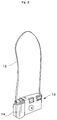
- a suspender 12 which is a strip made of plastics film as shown in Fig. 1 is wound around an outside (surfaces of the bottom, side and top) of a single-use camera 13.
- the suspender is fixed to the surface of the side and/or the surface of the bottom of the camera 13 via a fixing portion 14 (only one side is illustrated in Figs. 1 to 3).
- the camera 13 is packaged with packaging cardboard except a shutter portion and a lens portion, and the suspender 12 is fixed to the cardboard.
- the suspender 12 can be fixed directly to the plastics main body of the camera 13.
- the fixing portion 14 may be fixed by conventional fixing methods, e.g., using an adhesive or by heat seal.
- Fig. 1 shows the single-use camera from which a packaging film is removed for convenience of illustration.
- an elongation at break is in the range of 500% or more in a tensile test by radioautography using a dumbbell specimen measuring 3 mm in width and 3 cm in length, preferably about 500 to about 2000%, more preferably about 600 to about 2000%.
- the elongation at break can be measured according to the method prescribed in JIS Z1702.
- plastic materials for such polymer films are polyethylene, polypropylene and like polyolefins.
- linear low-density polyolefins are more preferable because they mostly exhibit satisfactory ductility or elongation at break in the above-mentioned ranges when used alone.
- polyethylene prepared using metallocene as a catalyst is more suitable since its elongation at break, extension elastic modulus, initial strength, and rate of 100% tensile stress to 50% tensile stress can be easily adjusted to a suitable range, by adjusting its thickness etc. in independent use or by adjusting its thickness in multi-layer use or a mixing rate when using together with other resins.
- a plastic film having a elongation at break of less than 500% (such as films made of polypropylene) and formed of one species of plastics may be given the foregoing range of elongation at break by incorporating or depositing a thermoplastic elastomer such as SEBS in a suitable amount (5 to 50 wt.%).
- a thermoplastic elastomer such as SEBS
- the film made of plastics for use as the suspender 12 may has a single layer structure or a multi-layer structure when so required.
- a material for the film to be deposited is polypropylene
- a multi-layer film (a layer of polyethylene and a layer of polypropylene) is suitable. More specifically such multi-layer film may be formed by depositing polypropylene on both sides of the polyethylene layer so as to impart the ductility and elongation at break in said desired range to the multi-layer film.
- the ductility and elongation at break of the multi-layer film can be adjusted to said desired range by changing the density of polyethylene in an intermediate layer or by using a random polymer or a homopolymer as polypropylene in two outer layers.
- the plastics film useful as the suspender 12 is made of a material having properties of scarcely shrinking after elongation.
- Preferred materials are those having an extension elastic modulus of 10% or less.
- the extension elastic modulus can be measured according to the method prescribed in JIS L1013.
- the plastics film useful as the suspender 12 has suitably an initial strength required for elongation in the range of about 5 to about 70 N, preferably about 10 to about 50 N. If the initial strength is too high, a great burden is imposed on the physical strength, namely the film is inferior in handleability.
- the plastics film useful as the suspender 12 has preferably a rate of 100% tensile stress to 50% tensile stress in the ranging from 1 to 1.5. In this range, the film can be elongated with a substantially uniform force.
- the term "50% tensile stress” refers to stress required for elongating the length of the film to 1.5 times, and "100% tensile stress” refers to stress required for elongating the length of the film to 2 times.
- the plastics film useful as the suspender 12 can be formed by conventional molding methods such as inflation molding methods, T die molding methods or the like.
- the suspender 12 can be easily elongated if the film is cut at a right angle to a direction of resin flow (to the extrusion direction). Hence this method is preferable.
- the plastics film useful as the suspender 12 can be easily elongated by partly reducing the width of the film, or can be more firmly fixed by extending the width of the fixing portion.
- the width of the suspender 12 can be suitably determined depending on the materials to be used, thickness, articles to which the film is fixed, etc. Generally the width thereof is 5 to 20 mm.
- the suspender 12 as described above can be easily attached to a camera by being merely fixed and is not bulky since it is a thin film.
- the suspender 12 requires no hole or no hook for its attachment to the camera main body.
- the suspender 12 can be used without modifying a mold for making the camera main body.
- the plastics film useful as the suspender 12 can be made at low costs and the cost can be lower.
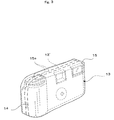
- the suspender 12 takes the shape of a loop formed along an outer periphery of the camera 13 so that even when the suspender 12 is stretched in use, the packaging cardboard covering the camera will not become broken. If the suspender 12 has an original length of, e.g., 20 cm, it can be elongated to a length of 60 to 100 cm in use as shown in Fig.2 so that the camera can be hung from our neck or our shoulder.
- Fig.3 is a perspective view of another example of a single-use camera having the suspender of the present invention.
- the packaging film 15 for packaging the single-use camera is formed of the material used for making the suspender 12, and a suspender 12' is defined by a perforation 15a formed in the packaging film 15.
- a fixing portion 14 to be fixed to the camera main body is formed in a specified portion of the film 15 corresponding to the suspender 12'.
- the packaging film 15 is cut away along the perforation 15a, whereby the suspender 12' is left.
- the suspender 12' when stretched, forms the same suspender as shown in Fig.2.
- the stretchable suspenders 12, 12' as described above can be used for containers such as PET bottles, aluminum cans, steel cans or the like containing refreshing drinks, tea, health beverages or the like.
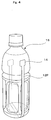
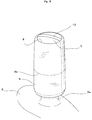
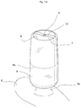
- Figs. 4 and 5 show embodiments wherein a stretchable suspender 12p is fixed to a PET bottle 16.
- the material for the suspender 12p is the same as used for the suspender 12 attached to the foregoing single-use camera. Therefore, a detailed description is omitted.
- the stretchable suspender 12p is fixed to both sides above the trunk of the PET bottle 16 via a fixing portion 14.
- the suspender 12p extends, before stretch, from an upper portion of one side of the bottle trunk to a bottom of the bottle along the side of the bottle trunk to run across the bottom and further extends upward from the bottom of the bottle along the other side to an upper portion of the bottle trunk.
- the suspender 12p arranged as described above does not cause a nuisance even when not used.
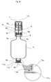
- the suspender 12p is stretched as in the case of the foregoing single-use camera (see Fig.5).
- the PET bottle 16 is capable of containing 500 mml of a liquid.
- the suspender 12p has a length of 40 cm before stretch and can be stretched to about 1 to about 1.5 m, whereby it can be suspended from our shoulder or our neck.
- the suspender 12p may be fixed directly to the main body of the PET bottle 16 or attached to a plastic film (label) on the bottle indicative of the name of an article of commerce.
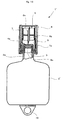
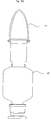
- a medication container 1 has a pair of openings 3a, 3b above and below a container main body 2 formed of plastics or the like, deformable under compression and accommodating a solution.
- the openings 3a, 3b have seal portions 4a, 4b made of an elastic material as shown in Fig. 8.
- a cylindrical support ring 5 upwardly extends around the seal portion 4a of the upper opening 3a and is removably fitted therein as shown in Fig.8.
- the support ring 5 supports a double-ended needle 6 with a pair of upper and lower needle points 6a, 6b communicating with each other such that the needle 6 is slidable upward and downward.
- the needle 6 is supported such that when the needle slides downward, the lower needle point 6b pierces the seal 4a of the upper opening 3a.
- the support ring 5 is covered with a protective cap 7.
- the support ring 5 is suitably detachably connected to the protective cap 7 via a fitting portion 7a.
- Fixed to the external periphery of the support ring 5 are both ends of the suspender 12 composed of a stretchable strip of the film made of plastics.
- the plastics film used as the suspender 12 is the same as described in respect of the foregoing embodiment of the suspender for the single-use camera.
- suspender 12 is fixed as scarcely loosed along the protective cap 7 as shown in the figure such that the protective cap 7 can not be easily removed without stretching the suspender 12, it would additionally provide a guarantee for non-opening of the protective cap 7. Hence, this structure is preferable.
- the suspender 12 is stretchable to a length sufficient to allow suspension even after insertion of the vial B (see Fig.17) into the support ring 5.
- a maximum gap of about 0.5 to about 3 mm between the top surface of the protective cap 7 and the suspender 12 may be formed to provide an opening for inserting the finger therein in stretching the suspender 12. Or as shown in Fig.12, if the suspender 12 is partly removably adhered to the top surface of the protective cap 7 as with an adhesive A, it may give a guarantee for non-opening of the protective cap 7.
- the support ring 5 and the protective cap 7 as well as the fixing portion of the suspender 12 are covered with a shrink film 8 as shown in a magnified view of Fig.9.
- the shrink film 8 extends from the periphery of the bottom of the support ring 5 through the outer periphery of the support ring 5 and the protective cap 7 to the periphery of the top surface of the protective cap 7 to achieve packaging in a sleeve form.
- the shrink film 8 is depicted as an opaque film in Fig.9 for the convenience sake of illustration but as a transparent film in Figs.6 to 8.
- the shrink film 8 has the perforation 8a in a joint between the support ring 5 and the protective cap 7 as shown in Fig.9.
- the opening 3b formed at the underside of the container main body 2 is used as an outlet for taking out the medication as shown in Fig.8.
- a cap 17 made of plastics for closing the seal portion 4b covers the opening 3b and is adhered thereto as a guarantee for non-opening of the opening 3b.
- the plastics cap 17 includes a cap main body 17a, a thin wall portion 17b (see an enlarged view of Fig.8), and a disc-shaped sealing portion 17c, these portions being integrally formed. When the sealing portion 17c is twisted with fingers, the thin wall portion 17b is cut and separated from the main body 17a, so that the internal seal portion 4b is seen.
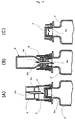
- the protective cap 7 is unscrewed from the screwed portion 7a with the support ring 5. Then, it is pulled off from the support ring 5. In pulling off, the plastic film constituting the suspender 12 is pulled and stretched to a required length while holding the plastic film together with the protective cap 7 or holding the plastic film alone.
- the upper needle point 6a is made to pierce a sealed opening (reference numeral B1 of Fig.17(b)) of the vial B.
- the double-ended needle 6 is made to slide downward along the support ring 5.
- the lower needle point 6b is made to successively pierce the seal portion 4 and a seal film 9a of an intermediate plug 9 (Fig.8) so that the vial is made to internally communicate with the container main body 2, allowing the contents of the vial and the main body 2 to become mixed after which the mixture is returned to the main body 2 of the container.
- the vial B can remain pierced with the upper needle point 6a.
- the medication container 1 having the double-ended needle and accommodating the mixture of the medication and the solution is used in drip administration by suspending the suspender 12 from the stand S for suspension as shown in Fig.11.
- the suspender 12 is a part of the shrink film 8 as shown in Fig.13, and is defined by the perforation 8b formed in the shrink film 8. A part of the suspender portion of the film defined by the perforation 8b may be fixed to the article to be suspended.
- the strip of plastics film useful as the suspender 12 may be provided with a rib 18 which extends in a length direction of the strip of plastics film to keep the shape as shown in Fig.14.
- the rib 18 for keeping the shape may be formed by integrally forming a thick wall portion constituting the rib in the strip when molding the film, or by laminating, adhering or depositing another layer.
- One or more ribs 18 for keeping the shape may be provided.
- the rib 18 may have various sectional shapes including a flat rectangular shape, a half-round shape and the like.
- the rib 18 may be provided only at a part of the suspender 12 according to the purpose instead of all over the suspender 12.
- the protective cap 7 When the suspender 12 is applied to the medication container as described above, the protective cap 7 is removed after stretching the suspender 12, and the vial is inserted.
- the suspender 12 becomes loose and may be placed on the double-ended needle 6 and on the support ring 5 in which case the suspender 12 is to be displaced.
- the suspender 12 having the rib for keeping the shape is prevented from causing the foregoing incident because of the shape-keeping ability after elongation of the suspender 12.
- the insertion of the vial can be quickly done.
- the shape-keeping rib 18 has a width size corresponding to about 20 to about 60% of the entire width of the strip of plastics film and may have a thickness of 50 to 300 ⁇ m.
- the rib need not be formed over the overall length of the suspender 12.
- the part of the suspender 12 having the shape-keeping rib 18 after elongation of the suspender 12 is higher in height than when the vial is inserted. Namely in this case, the loosened part of the suspender 12 not having the shape-keeping rib 18 does not obstruct the insertion of the vial.
- the medication container having the double-ended needle was described.
- the stretchable suspender of the invention can be further applied to a medication container having an outlet for taking out a solution of the medication alone, or a medication container of the type which is provided with an upper opening for mixing and injecting a medication and a lower opening for taking out a solution of the medication, but which is not provided with a double-ended needle.
- the suspender of the invention can be applied to various articles as well as to the above-mentioned examples.
- the suspender of the present invention is fixed to various articles in advance and is used as stretched in use so that it can be compactly accommodated before use. Further, the suspender of the invention which comprises a plastics film can be provided at low costs.
- the suspender has a structure wherein the suspender composed of a strip of plastics film stretchable in a length direction is fixed to the support ring and the shrink film covers the same, whereby the suspender does not hamper the shrink film and intravenous drip can be done with a vial combined therewith.
Landscapes
- Engineering & Computer Science (AREA)
- Mechanical Engineering (AREA)
- Health & Medical Sciences (AREA)
- Pharmacology & Pharmacy (AREA)
- Life Sciences & Earth Sciences (AREA)
- Animal Behavior & Ethology (AREA)
- General Health & Medical Sciences (AREA)
- Public Health (AREA)
- Veterinary Medicine (AREA)
- Details Of Rigid Or Semi-Rigid Containers (AREA)
- Packages (AREA)
- Medical Preparation Storing Or Oral Administration Devices (AREA)
Applications Claiming Priority (5)
| Application Number | Priority Date | Filing Date | Title |
|---|---|---|---|
| JP2002294589 | 2002-10-08 | ||
| JP2002294589 | 2002-10-08 | ||
| JP2003106169 | 2003-04-10 | ||
| JP2003106169 | 2003-04-10 | ||
| PCT/JP2003/012200 WO2004033330A1 (fr) | 2002-10-08 | 2003-09-25 | Structure formant un dispositif de levage, et contenant pour produits chimiques dote de ladite structure |
Publications (2)
| Publication Number | Publication Date |
|---|---|
| EP1557367A1 true EP1557367A1 (fr) | 2005-07-27 |
| EP1557367A4 EP1557367A4 (fr) | 2005-12-14 |
Family
ID=32095403
Family Applications (1)
| Application Number | Title | Priority Date | Filing Date |
|---|---|---|---|
| EP03748576A Withdrawn EP1557367A4 (fr) | 2002-10-08 | 2003-09-25 | Structure formant un dispositif de levage, et contenant pour produits chimiques dote de ladite structure |
Country Status (8)
| Country | Link |
|---|---|
| US (1) | US20060010651A1 (fr) |
| EP (1) | EP1557367A4 (fr) |
| JP (1) | JP4348555B2 (fr) |
| KR (1) | KR20050051685A (fr) |
| AU (1) | AU2003268669A1 (fr) |
| CA (1) | CA2497578A1 (fr) |
| TW (1) | TWI229590B (fr) |
| WO (1) | WO2004033330A1 (fr) |
Cited By (3)
| Publication number | Priority date | Publication date | Assignee | Title |
|---|---|---|---|---|
| WO2010064074A1 (fr) * | 2008-12-02 | 2010-06-10 | Becton Dickinson France | Récipient de médicament amélioré |
| US10213424B2 (en) | 2013-03-14 | 2019-02-26 | Fresenius Kabi Deutschland Gmbh | Morphine formulations |
| US10214338B2 (en) | 2013-03-14 | 2019-02-26 | Fresenius Kabi Deutschland Gmbh | Packaging system for oxygen-sensitive drugs |
Families Citing this family (4)
| Publication number | Priority date | Publication date | Assignee | Title |
|---|---|---|---|---|
| JP4745923B2 (ja) * | 2006-08-30 | 2011-08-10 | 株式会社サトー | 吊下げラベル |
| JP2008080103A (ja) * | 2006-08-31 | 2008-04-10 | Otsuka Pharmaceut Factory Inc | 薬剤容器 |
| WO2018148790A1 (fr) * | 2017-02-15 | 2018-08-23 | Torpy Peter Brian | Sécurité de mât de drapeau |
| US20210161259A1 (en) * | 2019-12-03 | 2021-06-03 | Elc Management Llc | Container With Tethered Closure |
Family Cites Families (14)
| Publication number | Priority date | Publication date | Assignee | Title |
|---|---|---|---|---|
| US2766907A (en) * | 1955-03-15 | 1956-10-16 | Robbins Instr Corp | Pressure infusion apparatus |
| US4086925A (en) * | 1976-10-12 | 1978-05-02 | Sherwood Medical Industries Inc. | Medical drainage device with adjustable supporting strap |
| DE2817250A1 (de) * | 1978-04-20 | 1979-10-31 | Henkel Kgaa | Tragegriff fuer einen verpackungsbehaelter |
| JPS5521967U (fr) * | 1978-07-29 | 1980-02-13 | ||
| US4301935A (en) * | 1980-01-10 | 1981-11-24 | Baxter Travenol Laboratories, Inc. | Container with hanger |
| JPS5918997Y2 (ja) * | 1980-12-13 | 1984-06-01 | 隆利 土橋 | 把手バンド |
| GB2206095B (en) * | 1987-06-16 | 1991-01-02 | Metal Box Co Ltd | Securing handles to plastics containers |
| US5059182A (en) * | 1989-04-12 | 1991-10-22 | David H. Laing | Portable infusion device |
| JPH0586836U (ja) * | 1992-01-16 | 1993-11-22 | 鐘淵化学工業株式会社 | 手提げ紐つき発泡樹脂製容器 |
| JPH06269311A (ja) * | 1993-03-22 | 1994-09-27 | Suupaa Planning:Kk | 使い捨カメラ用ケース |
| JPH0747329Y2 (ja) * | 1993-07-29 | 1995-11-01 | 株式会社ヤマモン | 紐付容器 |
| JPH08126683A (ja) * | 1994-10-31 | 1996-05-21 | Fujisawa Pharmaceut Co Ltd | 輸液用容器 |
| JP3891671B2 (ja) * | 1997-11-27 | 2007-03-14 | 花王株式会社 | 容器 |
| JP4048337B2 (ja) * | 1998-09-02 | 2008-02-20 | 株式会社大塚製薬工場 | 両頭針付き輸液容器 |
-
2003
- 2003-09-25 KR KR1020057006022A patent/KR20050051685A/ko not_active Abandoned
- 2003-09-25 AU AU2003268669A patent/AU2003268669A1/en not_active Abandoned
- 2003-09-25 JP JP2005501013A patent/JP4348555B2/ja not_active Expired - Fee Related
- 2003-09-25 WO PCT/JP2003/012200 patent/WO2004033330A1/fr not_active Ceased
- 2003-09-25 US US10/531,816 patent/US20060010651A1/en not_active Abandoned
- 2003-09-25 CA CA002497578A patent/CA2497578A1/fr not_active Abandoned
- 2003-09-25 EP EP03748576A patent/EP1557367A4/fr not_active Withdrawn
- 2003-09-30 TW TW92126990A patent/TWI229590B/zh not_active IP Right Cessation
Cited By (8)
| Publication number | Priority date | Publication date | Assignee | Title |
|---|---|---|---|---|
| WO2010064074A1 (fr) * | 2008-12-02 | 2010-06-10 | Becton Dickinson France | Récipient de médicament amélioré |
| US9731082B2 (en) | 2008-12-02 | 2017-08-15 | Fresenius Kabi Deutschland Gmbh | Drug container |
| US10661018B2 (en) | 2008-12-02 | 2020-05-26 | Fresenius Kabi Deutschland Gmbh | Drug container |
| US11426522B2 (en) | 2008-12-02 | 2022-08-30 | Fresenius Kabi Deutschland Gmbh | Drug container |
| US10213424B2 (en) | 2013-03-14 | 2019-02-26 | Fresenius Kabi Deutschland Gmbh | Morphine formulations |
| US10214338B2 (en) | 2013-03-14 | 2019-02-26 | Fresenius Kabi Deutschland Gmbh | Packaging system for oxygen-sensitive drugs |
| US10781027B2 (en) | 2013-03-14 | 2020-09-22 | Fresenius Kabi Deutschland Gmbh | Packaging system for oxygen-sensitive drugs |
| US11214426B2 (en) | 2013-03-14 | 2022-01-04 | Fresenius Kabi Deutschland Gmbh | Packaging system for oxygen-sensitive drugs |
Also Published As
| Publication number | Publication date |
|---|---|
| WO2004033330A1 (fr) | 2004-04-22 |
| CA2497578A1 (fr) | 2004-04-22 |
| JPWO2004033330A1 (ja) | 2006-02-09 |
| EP1557367A4 (fr) | 2005-12-14 |
| AU2003268669A1 (en) | 2004-05-04 |
| KR20050051685A (ko) | 2005-06-01 |
| TW200412874A (en) | 2004-08-01 |
| TWI229590B (en) | 2005-03-21 |
| JP4348555B2 (ja) | 2009-10-21 |
| US20060010651A1 (en) | 2006-01-19 |
Similar Documents
| Publication | Publication Date | Title |
|---|---|---|
| US6343717B1 (en) | Pre-filled disposable pipettes | |
| CA2905117C (fr) | Recipient | |
| US5429254A (en) | Aseptic infant feeding system | |
| US4629080A (en) | Container such as a nursing container, having formed enclosure chamber for a dispensing member | |
| EP2226263B1 (fr) | Conteneur en forme de sac à bec verseur | |
| KR100363601B1 (ko) | 투명구역을구비한힌지된용기 | |
| US8083102B2 (en) | Flexible pouch with a tube spout fitment and flexible sleeve | |
| JP2004099082A (ja) | 手放し詰め替え容器 | |
| US8573445B2 (en) | Flexible pouch with a tube spout fitment and flexible sleeve | |
| BRPI0709692A2 (pt) | embalagem resistente a rasgos e vazamentos para dispensar lìquidos de um modo controlado | |
| JPH03187857A (ja) | 詰め替え用注入口付き流動性製品パッケージ | |
| CN101203440A (zh) | 带有一体的附件和内部吸管的柔性直立袋 | |
| EP1557367A1 (fr) | Structure formant un dispositif de levage, et contenant pour produits chimiques dote de ladite structure | |
| JP5003037B2 (ja) | 注出口付きパウチ | |
| JP4097066B2 (ja) | 流動食用包装袋 | |
| CA2540635A1 (fr) | Appareil a membrane de restriction de porte flexible | |
| US6321944B1 (en) | Display apparatus for a collapsible tube dispenser | |
| EP0613833A1 (fr) | Ensemble de fermeture | |
| JP5070195B2 (ja) | 包装用容器、特に缶状容器 | |
| JP2003081378A (ja) | ストロー付き袋包装飲料品及びストロー | |
| US6588178B1 (en) | Method of forming plastic tubes with oriented labeling | |
| JPH0741010A (ja) | スタンドパウチ | |
| JP2005270157A (ja) | 薬剤容器 | |
| JPH057642U (ja) | 輸液バツグ | |
| JP2001240076A (ja) | 液体バッグおよび液体バッグの保持具 |
Legal Events
| Date | Code | Title | Description |
|---|---|---|---|
| PUAI | Public reference made under article 153(3) epc to a published international application that has entered the european phase |
Free format text: ORIGINAL CODE: 0009012 |
|
| 17P | Request for examination filed |
Effective date: 20050503 |
|
| AK | Designated contracting states |
Kind code of ref document: A1 Designated state(s): AT BE BG CH CY CZ DE DK EE ES FI FR GB GR HU IE IT LI LU MC NL PT RO SE SI SK TR |
|
| A4 | Supplementary search report drawn up and despatched |
Effective date: 20051031 |
|
| STAA | Information on the status of an ep patent application or granted ep patent |
Free format text: STATUS: THE APPLICATION IS DEEMED TO BE WITHDRAWN |
|
| 18D | Application deemed to be withdrawn |
Effective date: 20080401 |