EP1557524A2 - Mécanisme de levage et de basculement pour store vénitien - Google Patents
Mécanisme de levage et de basculement pour store vénitien Download PDFInfo
- Publication number
- EP1557524A2 EP1557524A2 EP05005916A EP05005916A EP1557524A2 EP 1557524 A2 EP1557524 A2 EP 1557524A2 EP 05005916 A EP05005916 A EP 05005916A EP 05005916 A EP05005916 A EP 05005916A EP 1557524 A2 EP1557524 A2 EP 1557524A2
- Authority
- EP
- European Patent Office
- Prior art keywords
- tilt
- lift
- cords
- slats
- rotation
- Prior art date
- Legal status (The legal status is an assumption and is not a legal conclusion. Google has not performed a legal analysis and makes no representation as to the accuracy of the status listed.)
- Withdrawn
Links
- 230000007246 mechanism Effects 0.000 title claims abstract description 100
- 238000006073 displacement reaction Methods 0.000 claims abstract description 10
- 230000000149 penetrating effect Effects 0.000 claims description 9
- 238000003780 insertion Methods 0.000 claims description 7
- 230000037431 insertion Effects 0.000 claims description 7
- 230000004308 accommodation Effects 0.000 claims description 3
- 238000007789 sealing Methods 0.000 claims 1
- 238000013016 damping Methods 0.000 description 11
- 239000000463 material Substances 0.000 description 8
- 230000000694 effects Effects 0.000 description 5
- 239000004744 fabric Substances 0.000 description 5
- 229910052751 metal Inorganic materials 0.000 description 3
- 239000002184 metal Substances 0.000 description 3
- 238000000034 method Methods 0.000 description 3
- 230000000717 retained effect Effects 0.000 description 3
- 238000004804 winding Methods 0.000 description 3
- 238000004140 cleaning Methods 0.000 description 2
- 230000001419 dependent effect Effects 0.000 description 2
- 239000011521 glass Substances 0.000 description 2
- 238000011065 in-situ storage Methods 0.000 description 2
- 238000004519 manufacturing process Methods 0.000 description 2
- 238000012986 modification Methods 0.000 description 2
- 230000004048 modification Effects 0.000 description 2
- 239000003566 sealing material Substances 0.000 description 2
- 229910000831 Steel Inorganic materials 0.000 description 1
- 239000004411 aluminium Substances 0.000 description 1
- 229910052782 aluminium Inorganic materials 0.000 description 1
- XAGFODPZIPBFFR-UHFFFAOYSA-N aluminium Chemical compound [Al] XAGFODPZIPBFFR-UHFFFAOYSA-N 0.000 description 1
- 239000002131 composite material Substances 0.000 description 1
- 230000006835 compression Effects 0.000 description 1
- 238000007906 compression Methods 0.000 description 1
- -1 felt Substances 0.000 description 1
- 239000011152 fibreglass Substances 0.000 description 1
- 150000002739 metals Chemical class 0.000 description 1
- 238000000465 moulding Methods 0.000 description 1
- 238000007493 shaping process Methods 0.000 description 1
- 239000010959 steel Substances 0.000 description 1
Images


Classifications
-
- E—FIXED CONSTRUCTIONS
- E06—DOORS, WINDOWS, SHUTTERS, OR ROLLER BLINDS IN GENERAL; LADDERS
- E06B—FIXED OR MOVABLE CLOSURES FOR OPENINGS IN BUILDINGS, VEHICLES, FENCES OR LIKE ENCLOSURES IN GENERAL, e.g. DOORS, WINDOWS, BLINDS, GATES
- E06B9/00—Screening or protective devices for wall or similar openings, with or without operating or securing mechanisms; Closures of similar construction
- E06B9/24—Screens or other constructions affording protection against light, especially against sunshine; Similar screens for privacy or appearance; Slat blinds
- E06B9/26—Lamellar or like blinds, e.g. venetian blinds
- E06B9/28—Lamellar or like blinds, e.g. venetian blinds with horizontal lamellae, e.g. non-liftable
- E06B9/30—Lamellar or like blinds, e.g. venetian blinds with horizontal lamellae, e.g. non-liftable liftable
- E06B9/303—Lamellar or like blinds, e.g. venetian blinds with horizontal lamellae, e.g. non-liftable liftable with ladder-tape
- E06B9/307—Details of tilting bars and their operation
-
- E—FIXED CONSTRUCTIONS
- E06—DOORS, WINDOWS, SHUTTERS, OR ROLLER BLINDS IN GENERAL; LADDERS
- E06B—FIXED OR MOVABLE CLOSURES FOR OPENINGS IN BUILDINGS, VEHICLES, FENCES OR LIKE ENCLOSURES IN GENERAL, e.g. DOORS, WINDOWS, BLINDS, GATES
- E06B9/00—Screening or protective devices for wall or similar openings, with or without operating or securing mechanisms; Closures of similar construction
- E06B9/24—Screens or other constructions affording protection against light, especially against sunshine; Similar screens for privacy or appearance; Slat blinds
- E06B9/26—Lamellar or like blinds, e.g. venetian blinds
- E06B9/28—Lamellar or like blinds, e.g. venetian blinds with horizontal lamellae, e.g. non-liftable
- E06B9/30—Lamellar or like blinds, e.g. venetian blinds with horizontal lamellae, e.g. non-liftable liftable
- E06B9/303—Lamellar or like blinds, e.g. venetian blinds with horizontal lamellae, e.g. non-liftable liftable with ladder-tape
- E06B9/308—Lamellar or like blinds, e.g. venetian blinds with horizontal lamellae, e.g. non-liftable liftable with ladder-tape with coaxial tilting bar and raising shaft
-
- E—FIXED CONSTRUCTIONS
- E06—DOORS, WINDOWS, SHUTTERS, OR ROLLER BLINDS IN GENERAL; LADDERS
- E06B—FIXED OR MOVABLE CLOSURES FOR OPENINGS IN BUILDINGS, VEHICLES, FENCES OR LIKE ENCLOSURES IN GENERAL, e.g. DOORS, WINDOWS, BLINDS, GATES
- E06B9/00—Screening or protective devices for wall or similar openings, with or without operating or securing mechanisms; Closures of similar construction
- E06B9/24—Screens or other constructions affording protection against light, especially against sunshine; Similar screens for privacy or appearance; Slat blinds
- E06B9/26—Lamellar or like blinds, e.g. venetian blinds
- E06B9/28—Lamellar or like blinds, e.g. venetian blinds with horizontal lamellae, e.g. non-liftable
- E06B9/30—Lamellar or like blinds, e.g. venetian blinds with horizontal lamellae, e.g. non-liftable liftable
- E06B9/32—Operating, guiding, or securing devices therefor
- E06B9/322—Details of operating devices, e.g. pulleys, brakes, spring drums, drives
-
- E—FIXED CONSTRUCTIONS
- E06—DOORS, WINDOWS, SHUTTERS, OR ROLLER BLINDS IN GENERAL; LADDERS
- E06B—FIXED OR MOVABLE CLOSURES FOR OPENINGS IN BUILDINGS, VEHICLES, FENCES OR LIKE ENCLOSURES IN GENERAL, e.g. DOORS, WINDOWS, BLINDS, GATES
- E06B9/00—Screening or protective devices for wall or similar openings, with or without operating or securing mechanisms; Closures of similar construction
- E06B9/24—Screens or other constructions affording protection against light, especially against sunshine; Similar screens for privacy or appearance; Slat blinds
- E06B9/26—Lamellar or like blinds, e.g. venetian blinds
- E06B9/28—Lamellar or like blinds, e.g. venetian blinds with horizontal lamellae, e.g. non-liftable
- E06B9/30—Lamellar or like blinds, e.g. venetian blinds with horizontal lamellae, e.g. non-liftable liftable
- E06B9/32—Operating, guiding, or securing devices therefor
- E06B9/327—Guides for raisable lamellar blinds with horizontal lamellae
-
- E—FIXED CONSTRUCTIONS
- E06—DOORS, WINDOWS, SHUTTERS, OR ROLLER BLINDS IN GENERAL; LADDERS
- E06B—FIXED OR MOVABLE CLOSURES FOR OPENINGS IN BUILDINGS, VEHICLES, FENCES OR LIKE ENCLOSURES IN GENERAL, e.g. DOORS, WINDOWS, BLINDS, GATES
- E06B9/00—Screening or protective devices for wall or similar openings, with or without operating or securing mechanisms; Closures of similar construction
- E06B9/24—Screens or other constructions affording protection against light, especially against sunshine; Similar screens for privacy or appearance; Slat blinds
- E06B9/26—Lamellar or like blinds, e.g. venetian blinds
- E06B9/38—Other details
- E06B9/384—Details of interconnection or interaction of tapes and lamellae
-
- E—FIXED CONSTRUCTIONS
- E06—DOORS, WINDOWS, SHUTTERS, OR ROLLER BLINDS IN GENERAL; LADDERS
- E06B—FIXED OR MOVABLE CLOSURES FOR OPENINGS IN BUILDINGS, VEHICLES, FENCES OR LIKE ENCLOSURES IN GENERAL, e.g. DOORS, WINDOWS, BLINDS, GATES
- E06B9/00—Screening or protective devices for wall or similar openings, with or without operating or securing mechanisms; Closures of similar construction
- E06B9/24—Screens or other constructions affording protection against light, especially against sunshine; Similar screens for privacy or appearance; Slat blinds
- E06B9/26—Lamellar or like blinds, e.g. venetian blinds
- E06B9/38—Other details
- E06B9/386—Details of lamellae
Definitions
- the present invention relates to lift and tilt mechanisms for Venetian blinds and to a Venetian blind comprising such mechanisms.
- the centrally located passages for the lift cord must necessarily be of a relative large lateral extension if the slats have to be able to undergo tilting over a major portion of the vertical tilt range from one of the slats' substantially vertical position through the horizontal position to the other substantially vertical position of the slats.
- GB 1 512 274 discloses slats for a venetian blind comprising longitudinally extending rounded flanges through which staples are driven and secured. Supporting strings are attached to these staples outside each longitudinal edge portion of the slats. This document furthermore discloses a special tool used to facilitate driving the staples through the flanges.
- a combined lift and tilt system comprising at least two pairs of tilt cords, each of the tilt cords being attached to the individual slats by means of releasable, preferably resilient clips for insertion into said edge portions of the slats.
- Running parallel with and preferably in close proximity to at least two pairs of said tilt cords there are provided lift cords, attached at the lower end to the lowermost slat of the Venetian blind and at the upper end to a combined lift and tilt mechanism, to which mechanism also the tilt cords are connected.
- the extension of the lift cords in parallel with the tilt cords may be ascertained by passing the lift cords through loops formed on the tilt cords for instance at the level of each individual slat, but other means of maintaining a parallel arrangement of the lift and tilt cords may also be conceived by a skilled person, without departing from the scope of the present invention.
- the combined lift- and tilt mechanism is positioned on a longitudinally extending shaft driven for rotation by appropriate drive means such as an electrical motor.
- the drive means can either be placed external of the shaft or be incorporated into a hollow portion of the shaft.
- the lift- and tilt mechanism comprises a tubular member mounted for rotation with and axial displacement over said drive shaft and guide means for maintaining the lift cords in their proper axial position and for directing the lift cords to the outer circumferential surface of said tubular member, whereby the lift cords upon rotation of said tubular member will become helically wound on or off the circumferential surface of the tubular member resulting in the slats being raised or lowered as the tubular member rotates.
- tubular member on the outer circumferential surface hereof is provided with a double thread for accommodating each of said lift cords of a given pair of lift cords in separate threads hereof.
- a third alternative embodiment of the lift- and tilt mechanism according to the invention said single/double thread provided on the outer circumferential surface of the tubular member is in engagement with a corresponding thread in a stationary bearing supporting the tubular member, this arrangement giving rise to the axial displacement of the tubular member and facilitates the proper winding on or off of the lift cords on the tubular member.
- a gap of sufficient dimensions is formed between said thread(s) on the tubular member and on the stationary bearing for accommodation of the lift cords in said gap.
- the lift- and tilt mechanism furthermore comprises tilt means for connection to the tilt cords of a given pair of lift- and tilt cords, said tilt means according to a first embodiment hereof comprising a cylindrical tilt house provided coaxially about said drive shaft and connected to this for co-rotation herewith, around the outer circumferential surface of which tilt house there is provided a tilt member following said rotation of the tilt house over a predetermined angular range due to friction between the tilt member and the tilt house.
- This range is determined by first means provided on the tilt member during said rotation being broad into contact with corresponding stationary abutment means.
- the tilt cords are wound around the tilt member, so that rotation of the tilt member in one direction makes one tilt cord of the given pair of tilt cords unwind from the tilt member and the other tilt cord of the given pair of tilt cords wind upon the tilt member.
- the slats can be broad to undergo a tilting movement over an angular range of approximately 180 degrees, i.e. the slats can tilt between a substantially vertical position, where adjacent edges of the slats are in contact with each other to form one closed surface of the venetian blind through a horizontal position of the slats and to the opposite, substantially vertical position of the slats.
- Modifications of the ratio between the diameters of the tilt house/tilt member and the width of the slats can be used to restrict the angular tilt range, if desirable.
- the tilt member encircling the tilt house can be radially rigid, but it is also possible to provide the tilt member according to the invention with a certain degree of radial resiliency.
- a tubular tilt member could be provided with a gap radially extending through the tilt member.
- Radial resiliency of the tilt member has the advantageous effect that once the rotation of the tilt member relative to the tilt house, as described above, is stopped by said engagement with the abutment means continued rotation of the drive shaft and the tilt house (for lowering or raising the slats) will tend to increase the inner diameter of the tilt member due to the fact that one end of the tilt member is prevented from rotation and that a frictional force is exerted between the contact surface of the tilt member and the tilt house.
- the drive means can use practically all of its power to raise or lower the slats without wasting power to overcome unnecessary friction between the tilt house and the tilt member. Substantial friction between the tilt house and the tilt member is thus only present, when it is needed, i.e. when the tilt of the slats must be changed, in which situation rotation of the tilt member is not prevented by engagement with the stationary abutment means.
- the tilt member is a tubular member comprising a main portion and a collar defining an intermediate groove for accommodating the tilt cords.
- the tilt mechanism is formed as a separate mechanism remote from the lift mechanism.
- a Venetian blind according to independent claim 17 and the dependent claims 18 to 27 that allows use of slats with dimensions that were hereto not possible.
- the overall rigidity of the slats must be sufficiently high, and this is attained according to the invention by providing slats comprising an elongated main portion on either longitudinal side hereof provided with edge portions comprising a first portion and an opposing second portion forming a space therebetween, where said edge portions are furthermore provided with a gap, through which gap said space is accessible from outside.
- edge portions on the one hand increases the overall rigidity of the slats and serves on the other hand as attachment means on the slats for connecting the slats to support cords or tilt cords, as will be described further in the following.
- the dimensions of said space are larger than the dimensions of the gap, whereby an attachment means connected to the support cords and inserted through said gap will be retained in a releasable manner within the space in the edge portions of the slats as will be described in more detail in the following.
- the rigidity of the slats is furthermore increased by providing said main portion with an arched cross-sectional shape, but other cross-sectional shapes, including planar slats, are also within the scope of the present invention.
- the main portion 2 could also be corrugated or even be provided with downwardly extending ribs on the bottom surface of the main portion.
- attachment means for releasable attachment of the slats to supporting cords are inserted into the edge portions through said gap, said attachment means being also attached to the supporting cords.
- the releasable attachment means may be resilient in order to make it pass through a gap surrounded by substantially rigid boundaries, but it is also possible according to the invention to surround the gap by resilient boundaries for passage of substantially rigid attachment means through the gap.
- the attachment means according to the invention is thus formed for insertion through said gap into said space for engagement with at least some of the boundaries of said space.
- the present venetian blind provides for slats with a width in excess of 200 mm, free spans between the supporting cords of up 2.5 m and more, slats with a length of at least 4 meters and a height of the blind of 6 m and more. It is understood that it is within the scope of the invention to apply more than two pairs of supporting cords if necessary in connection with very long slats, i.e. slats with a length by far exceeding the stated 4 meters.
- the slats according to the invention can be made of a number of different materials. Typically the slats are made of a suitable metal, such as aluminium or steel, but other metals can also be used. Also a composite material may be used or the slats can be moulded in fibreglass etc.
- the prime prerequisite governing the choice of material is the necessary rigidity of the slats, but it is possible to some extend to compensate for reduced rigidity due to the choice of material by proper shaping of the slats.
- This object is attained according to the invention by providing at least certain portions of the slats with an acoustic damping arrangement.
- This panel is preferably substantially planar, but other shapes could also be used, and may even prove desirable under certain circumstances.
- This panel can serve at least two functions.
- the slats may provide a more attractive appearance as seen from the bottom side of the slats and/or it may be utilised as an acoustic structure to improve the sound dampening characteristics of the slat.
- the panel may be provided with through holes or slits providing access to the region between the panel and the main portion of the slat and this region may be provided with appropriate sound damping material in a manner known per se.
- other sound damping structures such as a suitable fabric may also be used.
- two pairs of tilt cords are applied running in parallel with and in close proximity to two corresponding pairs of lift cords in the manner outlined above.
- the points of attachment of lift- and tilt cords to the slats are located at a distance from either end of the slats substantially equal to 1/5 of the total length of the slat, thus leaving a free span between the two pairs of lift/tilt cords of substantially 3/5 of the total length of the slats.
- other arrangements, comprising even more than two systems of lift- and tilt cords could also be used for instance for very long slats.
- vertically extending support cords or equivalent means are provided at either longitudinal end of the slats in order to increase the overall stability of the venetian blind both longitudinally and laterally, i.e. in a direction substantially perpendicular to the plane of the venetian blind.
- the slats are at either longitudinal end hereof provided with support members attached to the slats and provided with suitable passages through the member for passage of the support cords.
- the lift cords are - instead of running parallel with the tilt cords - guided along the support cords, for instance through the same or additional passages in the support members as the support cords.
- the lift cords are also in this case attached to the lowermost slat of the venetian blind.
- portions of the regions of the edges of the slats can be provided with sealing material, such as felt, rubber etc.
- the tilt and lift mechanism according to the invention makes it possible to operate the slats in such a manner that proper alignment of all slats both in situations where the slats are stationary and during raising, lowering and tilting operations is ensured.
- a complete darkening of the room would hence not be possible with slats comprising said passages, but can be attained with the venetian blind according to the invention. If necessary sealing material, such as rubber, felt etc. can even be provided at the edge portions of the slats to prevent light from penetrating between adjacent slats.
- the presence of the longitudinal edge portions along either edge of the slats increases the overall rigidity of the slats thus providing for venetian blinds of great longitudinal extension, typically with the application of only two pairs of lift- and tilt cords. It is thus possible to cover large surfaces, not necessarily only window openings, with a single venetian blind, having large extensions both horizontally and vertically.
- the attachment of the tilt cords along the edge portions makes both initial assembling of the venetian blind easy and also facilitates removal and replacement of single slats without the necessity to dismantle major parts of the whole venetian blind.
- the easy initial assembling of even venetian blinds of considerable dimensions furthermore opens up for the possibility to purchase the venetian blind in the form of a kit to be easily assembled in situ.
- the slats can for instance be kept in stock in form of very long slats, which can be sold in the lengths actually needed.
- the ease of assembling the venetian blind in situ is also advantageous from a transportation point of view.
- the slats may be used for altering the acoustical characteristics of a room by the provision of the various forms of acoustic damping arrangements on the slats.
- the tilting of the slats can even be utilised to alter the acoustical effect of the slats, it being possible to obtain either an acoustical hard surface, when the slats are in one of their vertical positions, or various degrees of acoustical damping, when the slats are tilted.
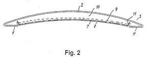
- the slat comprises a longitudinally extending main portion 2, which according to this embodiment is upwardly arched, although other cross sectional shapes may also be conceived.
- the slat comprises front and rear longitudinal edge portions 3 comprising first portions 3' in the following referred to as top portions, and is furthermore provided with inwardly extending second portions 4 - in the following referred to as bottom portions 4, which in the shown embodiment are substantially planar.
- These bottom portions 4 terminates in attachment portions 5 directed towards the bottom surface of the main portion 2 of the slat.
- the slat according to this embodiment may be produced in a simple manner by known techniques, such as roll forming.
- FIG 2 there is shown an optional embodiment of the slat 1 according to the invention, where the slat 1 has been provided with a bottom panel 7, which may be substantially planar as shown in figure 2, but which could also have other cross-sectional shapes.
- the panel may comprise one single unbroken surface, and for instance be provided for purely decorative purposes or it may be formed as a sound damping element in a manner known per se for instance by the provision of a suitable pattern of passages 8 through the panel.
- These passages can for instance be circular or have the form of elongated slits, although many other shapes would also be possible.
- the panels are provided with attachment portions 11 for releasable attachment to the slats 1 for instance along the attachment portions 5 or via the gaps 6 herein.
- the bottom panels 7 may furthermore be provided with a sound damping fabric 9 covering said passages 8.
- the internal volume 10 formed between the bottom panel 7 and the bottom surface of the main portion 2 of the slat 1 may be provided with appropriate acoustic damping material. It would also be possible solely to apply a fabric instead of the panel, and provide this fabric with suitable attachment means along the edges hereof.
- attachment means could be envisaged for the slats according to the present invention.
- the prime prerequisite for these attachment means is their ability to pass through the gap between the first and second edge portions of the slat and to be retained within the space between these portions after passage through the gap.
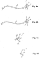
- attachment means 12 for use with the slats 2 according to the invention, where it is assumed, that the edge portions 3 are substantially rigid, i.e. the gap 6 is bounded by substantially rigid boundaries between 5 and 3'.
- the attachment means according to this embodiment consists of a clips of metal wire or other suitable material formed in a symmetrical manner about a central loop portion 16 and furthermore comprising a first leg portion 15 substantially in the plane of the central loop portion 16 and second and third leg portions 14, 13 in a plane forming an angle A relative to the plane of the central loop portion 16 and the first leg portion 15.
- the angle A is chosen in accordance with the corresponding angle B between the first and second edge portions 3' and 4 of the slat 2 in such a manner that the attachment means 12 becomes retained within the space 3" of the edge portion 3 after insertion through the gap 6.
- a cord 17 connects the slat 2 to the tilt cord 19, thereby suspending the slat 2 from the tilt cord 19.
- the cord 17 there is provided at loop 18, through which the lift cord 20 passes, whereby the lift cords 20 will run substantially parallel with the tilt cords 19.
- the attachment means shown in figure 3a and 3b can not be used in connection with the edge portions 3 shown in figure 4a and 4b.
- a couple of alternative embodiments of attachment means for use with the edge portions in figure 4a and 4b are shown in figure 4c and 4d.
- the attachment means shown in figure 4c comprises a cylindrical rod 23 made from a material of sufficient resiliency to allow it to pass through the gap 6 shown in figure 4a and 4b and provided with a circumferential groove 24 for fastening the cord 25 connected to the tilt cord 19.
- the cord 25 could also be embedded in the cylindrical rod 23 for instance during moulding hereof or passed through a passage provided in the cylindrical rod 23.
- a resilient sphere 26 as shown in figure 4d could also be used. It is understood that the above attachment means could alternatively be made of a rigid material if the edge portions 3 are resilient as described above.
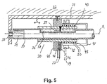
- FIG. 5 there is now shown a schematic representation of a first embodiment of a lift- and tilt mechanism 30 for use in the venetian blind according to the invention for controlling a single pair of lift- and tilt cords.
- This mechanism is attached to a housing 31 mounted for instance in the upper portion of a window opening or in the ceiling.
- the main components of the venetian blind according to the invention comprise a longitudinally extending shaft 33, which can be common for a number - typically two - of lift- and tilt mechanisms, although separate shafts 33 for each of a plurality of lift- and tilt mechanisms could also be envisaged, each being provided with suitable drive means, such as a motor designated by reference numeral 34.
- synchronisation of the lift- and tilt mechanisms are ascertained through application of a common drive shaft but in the latter case means for synchronisation of the different lift- and tilt mechanisms may be necessary.
- the shaft 33 is hollow for accommodation of the motor 34 within the shaft, but other arrangements of motors and drive means connecting the shaft and the drive shaft 35 of the motor could also be used without constituting a departure from the lift- and tilt mechanism according to the present invention.
- the drive shaft 35 of the motor is attached to the abovementioned housing 31.
- a tubular member 36 dimensioned for rotation with the shaft 33 and for axial displacement over a predetermined longitudinal distance of the shaft 33, this displacement being indicated by the arrow C in figure 4 and 5.
- the combined rotation with the shaft 33 and simultaneous displacement hereon is obtained according to this embodiment of the lift- and tilt mechanism by engagement between an engagement means 37 extending radially inward from the tubular member 36 and into engagement with a longitudinal channel 38 provided in the shaft 33.
- the tubular member 36 is mounted for rotation relative to the housing 31 by means of an appropriate bearing 40, which is only shown schematically in figure 4 and 5.
- a pair of lift cords 20 for raising or lowering of the slats 2 are wound helically around the tubular member 36.
- the lift cords 20 are in the embodiment shown directed through channels 46 provided in the bearing 40, but it is understood that other arrangements for maintaining the longitudinal position of the lift cords 20 could also be used without departing from the lift- and tilt mechanism according to the invention.
- the ends 43 of the lift cords are fixed to the tubular member 36.
- the winding of the lift cords 20 onto and off the tubular member 36 takes place in a double helical manner as indicated in the figures, where one lift cord is shown in black and the other in an open representation.
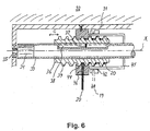
- FIG. 6 A second embodiment of the lift- and tilt mechanism according to the invention is shown in figure 6.
- the tubular member 36 is on the circumferential surface hereof provided with threads 39 for engagement with corresponding threads 44 in the stationary bearing 40.
- the longitudinal displacement of the tubular member 36 on the shaft 33 is attained by the engagement between the thread 39 on the tubular member 36 and the thread 44 in the stationary bearing 40.
- the thread on the tubular member 36 furthermore serves the purpose of ascertaining a reliable winding on and off of the lift cords 20 on the tubular member, as the thread is formed to accommodate the two lift cords 20 of a given pair of lift cords within a single groove of the thread.
- the thread according to this embodiment is thus a single thread formed to accommodate two cords in side by side relation in the single groove of the thread.
- the single thread comprised in the second embodiment is replaced by a double thread, each thread accommodating one of the lift cords 20 of the given pair of lift cords.
- the inner circumferential surface of a cylindrical tilt house 41 which will be described in the following, substantially touches the crests of the thread 39 on the tubular member 36, whereby substantially closed spaces for accommodating the lift cords 20 are formed between the tubular member 36 and the inner circumferential surface of the cylindrical tilt house 41, thus preventing the lift cords 20 from becoming entangled or leaving contact with the tubular member 36 during operation of the mechanism.
- said tilt mechanism comprises a cylindrical tilt house 41 provided coaxially about and connected to said drive shaft 33 for co-rotation herewith, around the outer circumferential surface of which tilt house 41 there is provided a circular, radially resilient tilt member 42.
- the tilt member 42 may comprise an axially extending gap 47 to allow the tilt member 42 to expand radially, although this is not a necessary prerequisite for the function of the tilt mechanism.
- the diameter of the tilt member 42 is chosen such that a frictional force is exerted between the tilt member and the tilt house 41, whereby a rotation of the tilt house 41 will cause the tilt member 42 to undergo rotation simultaneously with the tilt house 41 and the drive shaft 33.
- the rotation of the tilt member 42 in the direction of the arrow D will however be prevented, when a tongue 48 provided in the vicinity of the gap 47 makes contacts with a stationary abutment 50.
- rotation of the tilt member 42 will be prevented, when a tongue 49 makes contact with a stationary abutment 51.
- FIG 7b there is shown a schematic representation of details of the tilt mechanism according to the invention.
- the tilt cords 19 1 and 19 2 of the venetian blind are attached to substantially diametrically opposite points 56 and 57 respectively on the tilt member 42 and wound around the tilt member (accommodated in a groove 52 provided in the tilt member between a main portion 54 hereof and a collar 53, although this is not apparent from figure 7b).
- a rotation of the tilt member 42 which according to this embodiment of the tilt mechanism takes place over an angular range of approximately 360 degrees, corresponding either to contact between the tongue 48 and the abutment 50 or to contact between the tongue 49 and the abutment 51 (hidden behind the abutment 50 in figure 7b) makes one of the tilt cords 19 1 move for instance in a downward direction and the other tilt cord 19 2 move in an upward direction.
- the slats 2 attached to the tilt cords thus undergo a tilting movement.
- the angular tilt range of the slats 2 can be changed either by changing the diameter of the tilt house 41 or by changing the positions of the abutments 50, 51, thereby preventing the tilt member 42 from undergoing substantially a full 360 degrees rotation.
- the tilt cord 19 1 has been wound maximally off the tilt member 42, thus leaving approximately 1 ⁇ 2 turn of cord on the circumference of the tilt member 42.
- the other tilt cord 19 2 is wound maximally on the tilt member 42 corresponding to approximately 1 1 ⁇ 2 turn of cord.
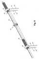
- FIG 8 An alternative embodiment of the lift- and tilt mechanism according to the invention is shown in figure 8.
- the lift- and tilt mechanisms are provided on the drive shaft 33 in the form of separate mechanisms remote from each other.
- the tilt mechanism 62 is furthermore designed to operate both pairs of tilt cords 19, although it would also be possible to provide tilt mechanisms for each of the pairs of tilt cords as described previously.
- the lift mechanisms shown in figure 8 are of the embodiment comprising threads to accommodate the lift cords, either of the single-thread or double-thread type as described previously, although a mechanism without threads could also in principle be used.
- other housings (not shown) for closing the open region(s) of the threads and for protecting the tubular member and the lift cords wound around this may be provided as previously discussed.
- the drive shaft is in figure 8 driven by a suitable motor. This could be inserted in the drive shaft, the drive shaft being for this purpose split up into two sections, but it is understood that other means of driving the shaft 33 may also be employed, as for instance a motor housed within a hollow portion of the drive shaft as previously described.
- the tilt mechanism is supported by a stationary bearing 59 and comprises a tilt drum 60 mounted for rotation with the drive shaft 33, for instance by means of a suitable slot and key arrangement 70.
- a tilt member 61 cut up longitudinally by a slit for facilitating radial expansion/compression of the tilt member.
- Two abutment means 63 are provided proximate to said slit, i.e. at either circumferential end of the tilt member.
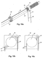
- Tilt cords 19 are directed from the slats via suitable systems of pulleys (for instance 69) and wound around the tilt member in a manner corresponding for instance to that shown previously in connection with the first embodiment of tilt mechanism.
- Such tilt cords are indicated in figure 9, but the manner in which they are actually wound around the tilt member can be subject to variations, which would be obvious to a person skilled in the art.
- they are attached to the first abutment means 63, but attachment of the tilt cords to the tilt member could take place at other circumferential positions as well.
- only one of the tilt cords of each pair of tilt cords is shown in figure 9, but the corresponding tilt cords are also connected to the tilt member, in the figure hidden from view by the tilt mechanism and the drive shaft 33.
- the range of rotation of the rotatable abutment ring 64 - and hence of the tilt member 61 around the tilt drum 60 - is determined by the circumferential extent of the abutment portion 66. Hence, by proper choice of the circumferential extent of the abutment portion, the desired rotation range can be set.
- FIG. 10b shows a first alternative comprising two pulleys 69
- figure 10c shows a second alternative comprising only a single pulley 69.
- the pulleys are located within the stationary bearing 40 and suitable openings and/or channels for the lift cords are provided in the stationary bearing.
- Other routing mechanisms for the lift cords may also be envisaged by a person skilled in the art.
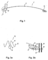
- FIG 11 there is shown an overview of an embodiment of a venetian blind according to the invention comprising the slats 2, attachment means 12 and lift- and tilt mechanism 30 according to one embodiment of the invention as described in detail above.
- the slats can as an option be provided with resilient bands in contact regions between adjacent slats in order to prevent light from penetrating the contact regions between the slats. Also such resilient bands would prevent the generation of noise when adjacent slats are broad into contact with each other during operation of the venetian blind.
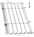
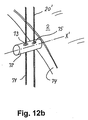
- FIG. 12a and 12b there is shown an alternative embodiment of the venetian blind according to the invention, where vertically extending support cords 71 are provided at either longitudinal end of the slats 2 in order to increase overall stability of the venetian blind.
- support cords Although referred to as support cords, it is understood that other means for instance substantially rigid rods of suitable dimensions could also be used.
- the support cords 71 pass through a passage 73 provided in a support member 72 attached to the longitudinal end of the slat, and for this purpose the end of the slat can be provided with an end cap or member 74 formed for instance for insertion into the hollow structure of the slat.
- the support member 72 is mounted for rotation about the axis X' through the member, i.e. for rotation relative to the slat.
Landscapes
- Engineering & Computer Science (AREA)
- Structural Engineering (AREA)
- Architecture (AREA)
- Civil Engineering (AREA)
- Blinds (AREA)
Applications Claiming Priority (3)
| Application Number | Priority Date | Filing Date | Title |
|---|---|---|---|
| DK200300485 | 2003-03-31 | ||
| DKPA200300485 | 2003-03-31 | ||
| EP04724338A EP1490573A1 (fr) | 2003-03-31 | 2004-03-30 | Venitienne |
Related Parent Applications (1)
| Application Number | Title | Priority Date | Filing Date |
|---|---|---|---|
| EP04724338A Division EP1490573A1 (fr) | 2003-03-31 | 2004-03-30 | Venitienne |
Publications (2)
| Publication Number | Publication Date |
|---|---|
| EP1557524A2 true EP1557524A2 (fr) | 2005-07-27 |
| EP1557524A3 EP1557524A3 (fr) | 2009-05-27 |
Family
ID=33104005
Family Applications (2)
| Application Number | Title | Priority Date | Filing Date |
|---|---|---|---|
| EP04724338A Withdrawn EP1490573A1 (fr) | 2003-03-31 | 2004-03-30 | Venitienne |
| EP05005916A Withdrawn EP1557524A3 (fr) | 2003-03-31 | 2004-03-30 | Mécanisme de levage et de basculement pour store vénitien |
Family Applications Before (1)
| Application Number | Title | Priority Date | Filing Date |
|---|---|---|---|
| EP04724338A Withdrawn EP1490573A1 (fr) | 2003-03-31 | 2004-03-30 | Venitienne |
Country Status (5)
| Country | Link |
|---|---|
| US (1) | US7654301B2 (fr) |
| EP (2) | EP1490573A1 (fr) |
| JP (1) | JP5089978B2 (fr) |
| CN (1) | CN1795317B (fr) |
| WO (1) | WO2004088085A1 (fr) |
Cited By (6)
| Publication number | Priority date | Publication date | Assignee | Title |
|---|---|---|---|---|
| FR2929637A1 (fr) * | 2008-04-07 | 2009-10-09 | Franciaflex | Store motorise a lames monobloc |
| US7779886B2 (en) | 2006-09-19 | 2010-08-24 | Holis Metal Industries Ltd. | Dual function mechanism for a Venetian blind |
| WO2011020881A1 (fr) | 2009-08-21 | 2011-02-24 | Jørn Krab Holding APS | Mécanismes de levage pour store vénitien |
| US9222302B2 (en) | 2013-12-27 | 2015-12-29 | Pella Corporation | Fenestration covering lift system and method |
| US9482046B2 (en) | 2013-12-27 | 2016-11-01 | Pella Corporation | Fenestration covering tilt system and method |
| EP3228805A1 (fr) | 2016-04-05 | 2017-10-11 | Holis Industries Ltd. | Mécanisme de régulation pour store vénitien |
Families Citing this family (24)
| Publication number | Priority date | Publication date | Assignee | Title |
|---|---|---|---|---|
| US8381793B2 (en) * | 2003-03-31 | 2013-02-26 | Joern Krab Holding Aps | Lift and tilt mechanisms for a venetian blind |
| AU2007240242B2 (en) * | 2006-12-19 | 2014-02-20 | Hunter Douglas Industries B.V. | Louver |
| DE102007002616A1 (de) * | 2007-01-12 | 2008-08-07 | Hydro Building Systems Gmbh | Sonnenschutzlamelle, insbesondere zur Abschattung von Gebäude-, Dach- und Fensterflächen |
| EP2112317A3 (fr) | 2008-04-23 | 2012-03-28 | Jørn Krab Holding APS | Revêtements motorisés pour ouvertures de bâtiment |
| EP2169166A3 (fr) | 2008-09-29 | 2012-07-04 | Jørn Krab Holding APS | Revêtements motorisés pour ouvertures de bâtiments |
| AU2009100562B4 (en) * | 2009-06-10 | 2009-09-03 | Liftmaster Electronics Pty Ltd | Blind slat |
| US20130048234A1 (en) * | 2010-03-10 | 2013-02-28 | Jorn Krab Holding Aps | Dual drum lift mechanism for venetian blinds |
| US8281843B2 (en) * | 2010-04-16 | 2012-10-09 | Teh Yor Co., Ltd. | Actuator mechanism for venetian blinds |
| JP5937296B2 (ja) | 2010-05-07 | 2016-06-22 | 株式会社ニチベイ | 横型ブラインド |
| US9091115B2 (en) | 2010-10-18 | 2015-07-28 | Qmotion Incorporated | Motorizable tilt shade system and method |
| JP5713873B2 (ja) * | 2011-11-08 | 2015-05-07 | 株式会社ニチベイ | 横型ブラインド |
| CN102900347B (zh) | 2012-07-30 | 2014-02-26 | 杭州欧卡索拉科技有限公司 | 带凸轮插销翻转机构的百叶窗卷轮系统 |
| CN102839906B (zh) | 2012-07-30 | 2013-10-30 | 杭州欧卡索拉科技有限公司 | 带不完全齿轮翻转机构的百叶窗卷轮系统 |
| CN102808577B (zh) | 2012-07-30 | 2013-08-28 | 杭州欧卡索拉科技有限公司 | 百叶窗的卷轮机构及带齿轮离合器翻转机构的卷轮系统 |
| CN103266847B (zh) * | 2012-09-29 | 2015-03-25 | 杭州欧卡索拉科技有限公司 | 百叶窗销轴卷轮机构与不完全齿轮翻转机构的卷轮系统 |
| TW201634804A (zh) * | 2015-01-23 | 2016-10-01 | Tachikawa Blind Mfg | 橫式百葉窗 |
| KR101712142B1 (ko) * | 2015-05-14 | 2017-03-03 | (주)블라인드팩토리 | 영역별 블라인드 슬랫 조절 장치 |
| US10550635B2 (en) | 2017-08-09 | 2020-02-04 | Whole Space Industries Ltd | Window covering control apparatus |
| US10676988B2 (en) | 2017-09-20 | 2020-06-09 | Whole Space Industries Ltd. | Window covering control apparatus |
| WO2019151945A1 (fr) * | 2018-01-31 | 2019-08-08 | Gliderol Doors (S) Pte Ltd | Ensemble lame pour volet roulant, volet roulant et procédés de fabrication de celui-ci |
| USD935221S1 (en) | 2019-06-26 | 2021-11-09 | Whole Space Industries Ltd | Bottom rail for a window covering |
| US20220356755A1 (en) * | 2019-07-24 | 2022-11-10 | Lutron Technology Company Llc | Window blind slat attachment |
| TWM612174U (zh) * | 2020-12-22 | 2021-05-21 | 慶豐富實業股份有限公司 | 電動窗簾捲線結構 |
| US12565809B2 (en) * | 2022-08-04 | 2026-03-03 | Guangzhou JADY Window Coverings Technology Co., Ltd | Day-and-night curtain dual-rail dual-control correlation type stopper |
Citations (2)
| Publication number | Priority date | Publication date | Assignee | Title |
|---|---|---|---|---|
| JPS60135490U (ja) * | 1984-02-20 | 1985-09-09 | 佐々木ブラインド工業株式会社 | ベネシヤンブラインドのスラツト水平維持装置 |
| US20010035269A1 (en) * | 2000-04-14 | 2001-11-01 | Ren Judkins | Lift system having length adjustment for window blinds |
Family Cites Families (34)
| Publication number | Priority date | Publication date | Assignee | Title |
|---|---|---|---|---|
| US2130320A (en) * | 1936-04-15 | 1938-09-13 | United Metal Box Co Inc | Venetian blind tape |
| US2174249A (en) * | 1936-05-14 | 1939-09-26 | H B Dodge And Company | Venetian blind |
| US2130318A (en) * | 1936-12-12 | 1938-09-13 | Trussell Mfg Co | Wire forming machine and method |
| US2152117A (en) * | 1937-01-28 | 1939-03-28 | Nat Lock Co | Venetian blind |
| US2381060A (en) * | 1944-05-11 | 1945-08-07 | Lewis I Kahn | Venetian blind structure |
| CH308832A (de) * | 1953-02-28 | 1955-08-15 | Wilhelm Karl | Führungsteil für die Lamellen von Lamellenstoren. |
| DK103006C (da) * | 1961-03-17 | 1965-11-01 | Hunter Douglas Int Quebec Ltd | Persienne forsynet med en hejsemekanisme for lamellerne og med en låsemekanisme samt låsemekanisme til en sådan persienne. |
| US3818969A (en) * | 1969-05-29 | 1974-06-25 | Levolor Lorentzen Inc | Inclined-plane venetian-blind installation |
| US3916973A (en) * | 1973-03-19 | 1975-11-04 | Hueppe Justin Fa | Venetian blind |
| CH591006A5 (fr) | 1975-07-23 | 1977-08-31 | Schenker Emil Storen Und Masch | |
| US4154281A (en) * | 1975-07-23 | 1979-05-15 | Storen- Und Maschinenfabrik Emil Schenker Ag | Venetian blind |
| AT369130B (de) * | 1976-08-23 | 1982-12-10 | Griesser Ag | Rafflamellenstore |
| DE2726452A1 (de) * | 1977-06-11 | 1979-05-23 | Hunter Douglas Ind Bv | Antrieb fuer eine lamellenjalousie |
| JPS5844797Y2 (ja) * | 1978-12-27 | 1983-10-11 | 立川ブラインド工業株式会社 | 横型ブラインドの上下索巻取装置 |
| CH652168A5 (en) * | 1981-10-27 | 1985-10-31 | Planya Ag | Gatherable lamellar blind |
| DE8503041U1 (de) * | 1985-02-05 | 1985-11-14 | Hunter Douglas Industries B.V., Rotterdam | Lamellenjalousie |
| JPH0234877Y2 (fr) * | 1986-08-26 | 1990-09-19 | ||
| JPH0668232B2 (ja) * | 1988-04-04 | 1994-08-31 | ヤマハ株式会社 | ブラインド用スラットの製法 |
| JPH0516396Y2 (fr) * | 1987-08-08 | 1993-04-28 | ||
| DE3819920A1 (de) | 1988-06-11 | 1989-12-21 | Warema Renkhoff Gmbh & Co Kg | Anordnung zur gelenkigen lamellenaufhaengung bei einer raffbaren lamellenjalousie |
| JPH0750551Y2 (ja) * | 1988-09-10 | 1995-11-15 | 立川ブラインド工業株式会社 | ブラインドのスラット昇降装置 |
| EP0380346B1 (fr) * | 1989-01-25 | 1994-04-13 | Kabushiki Kaisha Nichibei | Dispositif pour l'entraînement et la rotation des lamelles d'un store vénitien du type horizontal |
| JPH0623297Y2 (ja) * | 1989-12-28 | 1994-06-22 | 昭和精機株式会社 | 自動噴射装置の噴射量調節機構 |
| DE69125238T2 (de) * | 1990-10-11 | 1997-07-17 | Toso Co | Jalousieaufzieh- und Wendemechanismus |
| DE4034614C3 (de) * | 1990-10-31 | 1999-02-25 | Warema Renkhoff Gmbh & Co Kg | Vorrichtung zum Verschatten von Fensterflächen |
| JPH079054A (ja) * | 1990-11-28 | 1995-01-13 | Vergola Internatl Pty Ltd | エンド・キャップ |
| JP2548133Y2 (ja) * | 1991-11-22 | 1997-09-17 | 株式会社ニチベイ | ブラインドの昇降コード巻取装置 |
| JP2695553B2 (ja) * | 1991-11-22 | 1997-12-24 | 株式会社ニチベイ | ブラインドの昇降回転機構 |
| JPH10266734A (ja) * | 1997-03-26 | 1998-10-06 | Toda Constr Co Ltd | 吸音ブラインド |
| JP3563621B2 (ja) * | 1998-12-22 | 2004-09-08 | 立川ブラインド工業株式会社 | ブラインド |
| EP1052365B1 (fr) * | 1999-05-11 | 2004-12-29 | Hunter Douglas Industries B.V. | Dispositif d'entraînement pour un store vénitien |
| JP3542742B2 (ja) * | 1999-06-30 | 2004-07-14 | 立川ブラインド工業株式会社 | 遮蔽材の昇降装置 |
| AU2002212098A1 (en) * | 2000-10-27 | 2002-05-06 | Art Andersen A/S | Venetian blind |
| CN1386951A (zh) * | 2002-06-18 | 2002-12-25 | 永森(博罗)塑胶有限公司 | 异形叶片百叶窗帘 |
-
2004
- 2004-03-30 WO PCT/IB2004/050363 patent/WO2004088085A1/fr not_active Ceased
- 2004-03-30 JP JP2006506794A patent/JP5089978B2/ja not_active Expired - Fee Related
- 2004-03-30 CN CN2004800145236A patent/CN1795317B/zh not_active Expired - Fee Related
- 2004-03-30 EP EP04724338A patent/EP1490573A1/fr not_active Withdrawn
- 2004-03-30 EP EP05005916A patent/EP1557524A3/fr not_active Withdrawn
- 2004-03-30 US US10/551,519 patent/US7654301B2/en not_active Expired - Fee Related
Patent Citations (2)
| Publication number | Priority date | Publication date | Assignee | Title |
|---|---|---|---|---|
| JPS60135490U (ja) * | 1984-02-20 | 1985-09-09 | 佐々木ブラインド工業株式会社 | ベネシヤンブラインドのスラツト水平維持装置 |
| US20010035269A1 (en) * | 2000-04-14 | 2001-11-01 | Ren Judkins | Lift system having length adjustment for window blinds |
Cited By (8)
| Publication number | Priority date | Publication date | Assignee | Title |
|---|---|---|---|---|
| US7779886B2 (en) | 2006-09-19 | 2010-08-24 | Holis Metal Industries Ltd. | Dual function mechanism for a Venetian blind |
| FR2929637A1 (fr) * | 2008-04-07 | 2009-10-09 | Franciaflex | Store motorise a lames monobloc |
| EP2108778A3 (fr) * | 2008-04-07 | 2014-01-15 | Franciaflex | Store motorisé à lames monobloc |
| WO2011020881A1 (fr) | 2009-08-21 | 2011-02-24 | Jørn Krab Holding APS | Mécanismes de levage pour store vénitien |
| EP2295703A1 (fr) | 2009-08-21 | 2011-03-16 | Jørn Krab Holding APS | Mécanisme de relevage pour store vénitien |
| US9222302B2 (en) | 2013-12-27 | 2015-12-29 | Pella Corporation | Fenestration covering lift system and method |
| US9482046B2 (en) | 2013-12-27 | 2016-11-01 | Pella Corporation | Fenestration covering tilt system and method |
| EP3228805A1 (fr) | 2016-04-05 | 2017-10-11 | Holis Industries Ltd. | Mécanisme de régulation pour store vénitien |
Also Published As
| Publication number | Publication date |
|---|---|
| US7654301B2 (en) | 2010-02-02 |
| HK1093545A1 (en) | 2007-03-02 |
| CN1795317A (zh) | 2006-06-28 |
| CN1795317B (zh) | 2012-02-01 |
| EP1490573A1 (fr) | 2004-12-29 |
| EP1557524A3 (fr) | 2009-05-27 |
| JP2006522245A (ja) | 2006-09-28 |
| US20060225849A1 (en) | 2006-10-12 |
| JP5089978B2 (ja) | 2012-12-05 |
| WO2004088085A1 (fr) | 2004-10-14 |
Similar Documents
| Publication | Publication Date | Title |
|---|---|---|
| US7654301B2 (en) | Venetian blind | |
| US8381793B2 (en) | Lift and tilt mechanisms for a venetian blind | |
| KR20100029105A (ko) | 선택식 틸팅 동작을 하는 가변형 반경 랩 이중-피치의 블라인드 | |
| US20130333849A1 (en) | Window Treatment having an Adjustable Bottom Bar | |
| CN102482914B (zh) | 用于活动百叶窗的提升机构 | |
| US20050045279A1 (en) | Window covering and method of use | |
| US5297608A (en) | Tilter mechanism | |
| US20070169900A1 (en) | Rolling up curtain device | |
| KR20100113690A (ko) | 전동 브라인드 | |
| CN105003186B (zh) | 一种窗帘绳固定座 | |
| AU2003201017A1 (en) | Electric blind | |
| TW201510343A (zh) | 用於將百葉窗葉片傾斜的系統及方法 | |
| US7308927B2 (en) | Window blind system | |
| JPH0673970A (ja) | ブラインド | |
| KR20110085337A (ko) | 슬랫의 완전차광 및 현수시 쏠림방지 기능을 갖는 베니션 블라인드 | |
| JPH0430310Y2 (fr) | ||
| DK200400113U3 (da) | Persienne | |
| HK1093545B (en) | Venetian blind | |
| KR102935725B1 (ko) | 사생활 보호기능을 갖는 베네시안 블라인드 | |
| KR100532227B1 (ko) | 전동블라인드용 각도조절장치 | |
| JP6738740B2 (ja) | 横型ブラインド | |
| JPH036798Y2 (fr) | ||
| KR102669666B1 (ko) | 수직, 수평, 경사각으로 설치 가능한 전동식 롤 블라인드 | |
| CN1643229A (zh) | 百叶窗 | |
| JPH0215988Y2 (fr) |
Legal Events
| Date | Code | Title | Description |
|---|---|---|---|
| PUAI | Public reference made under article 153(3) epc to a published international application that has entered the european phase |
Free format text: ORIGINAL CODE: 0009012 |
|
| AC | Divisional application: reference to earlier application |
Ref document number: 1490573 Country of ref document: EP Kind code of ref document: P |
|
| AK | Designated contracting states |
Kind code of ref document: A2 Designated state(s): AT BE BG CH CY CZ DE DK EE ES FI FR GB GR HU IE IT LI LU MC NL PL PT RO SE SI SK TR |
|
| AX | Request for extension of the european patent |
Extension state: AL LT LV MK |
|
| RAP1 | Party data changed (applicant data changed or rights of an application transferred) |
Owner name: JORN KRAB HOLDING APS |
|
| RIC1 | Information provided on ipc code assigned before grant |
Ipc: E06B 9/322 20060101ALI20080328BHEP Ipc: E06B 9/307 20060101ALI20080328BHEP Ipc: E06B 9/32 20060101ALI20080328BHEP Ipc: E06B 9/327 20060101ALI20080328BHEP Ipc: E06B 9/386 20060101ALI20080328BHEP Ipc: E06B 9/384 20060101ALI20080328BHEP Ipc: E06B 9/308 20060101AFI20080328BHEP |
|
| PUAL | Search report despatched |
Free format text: ORIGINAL CODE: 0009013 |
|
| AK | Designated contracting states |
Kind code of ref document: A3 Designated state(s): AT BE BG CH CY CZ DE DK EE ES FI FR GB GR HU IE IT LI LU MC NL PL PT RO SE SI SK TR |
|
| AX | Request for extension of the european patent |
Extension state: AL LT LV MK |
|
| 17P | Request for examination filed |
Effective date: 20091127 |
|
| AKX | Designation fees paid |
Designated state(s): AT BE BG CH CY CZ DE DK EE ES FI FR GB GR HU IE IT LI LU MC NL PL PT RO SE SI SK TR |
|
| AXX | Extension fees paid |
Extension state: LV Payment date: 20091127 Extension state: LT Payment date: 20091127 |
|
| 17Q | First examination report despatched |
Effective date: 20140204 |
|
| STAA | Information on the status of an ep patent application or granted ep patent |
Free format text: STATUS: THE APPLICATION IS DEEMED TO BE WITHDRAWN |
|
| 18D | Application deemed to be withdrawn |
Effective date: 20140815 |