EP1557553B1 - Einblockarm für eine Nachverbrennungsvorrichtung eines Triebwerkes mit Doppelströmung - Google Patents
Einblockarm für eine Nachverbrennungsvorrichtung eines Triebwerkes mit Doppelströmung Download PDFInfo
- Publication number
- EP1557553B1 EP1557553B1 EP05290134A EP05290134A EP1557553B1 EP 1557553 B1 EP1557553 B1 EP 1557553B1 EP 05290134 A EP05290134 A EP 05290134A EP 05290134 A EP05290134 A EP 05290134A EP 1557553 B1 EP1557553 B1 EP 1557553B1
- Authority
- EP
- European Patent Office
- Prior art keywords
- walls
- arm according
- casing
- arm
- passage
- Prior art date
- Legal status (The legal status is an assumption and is not a legal conclusion. Google has not performed a legal analysis and makes no representation as to the accuracy of the status listed.)
- Expired - Lifetime
Links
- 239000002131 composite material Substances 0.000 claims description 10
- 238000002485 combustion reaction Methods 0.000 claims description 6
- 239000000919 ceramic Substances 0.000 claims description 3
- 239000011159 matrix material Substances 0.000 claims description 3
- 235000020637 scallop Nutrition 0.000 claims 3
- 241000237503 Pectinidae Species 0.000 claims 2
- 241000237509 Patinopecten sp. Species 0.000 claims 1
- 230000004907 flux Effects 0.000 description 3
- 239000007789 gas Substances 0.000 description 3
- 239000000446 fuel Substances 0.000 description 2
- 238000007373 indentation Methods 0.000 description 2
- 238000004519 manufacturing process Methods 0.000 description 2
- 239000000463 material Substances 0.000 description 2
- 239000002184 metal Substances 0.000 description 2
- 239000007769 metal material Substances 0.000 description 2
- 230000035882 stress Effects 0.000 description 2
- 230000008646 thermal stress Effects 0.000 description 2
- 210000003462 vein Anatomy 0.000 description 2
- OKTJSMMVPCPJKN-UHFFFAOYSA-N Carbon Chemical compound [C] OKTJSMMVPCPJKN-UHFFFAOYSA-N 0.000 description 1
- 229910052799 carbon Inorganic materials 0.000 description 1
- 238000005255 carburizing Methods 0.000 description 1
- 239000011153 ceramic matrix composite Substances 0.000 description 1
- 230000000295 complement effect Effects 0.000 description 1
- 238000001816 cooling Methods 0.000 description 1
- 239000000835 fiber Substances 0.000 description 1
- 239000007792 gaseous phase Substances 0.000 description 1
- 238000002347 injection Methods 0.000 description 1
- 239000007924 injection Substances 0.000 description 1
- 239000007791 liquid phase Substances 0.000 description 1
- 238000012423 maintenance Methods 0.000 description 1
- 235000012830 plain croissants Nutrition 0.000 description 1
- 230000001681 protective effect Effects 0.000 description 1
- 230000003014 reinforcing effect Effects 0.000 description 1
- HBMJWWWQQXIZIP-UHFFFAOYSA-N silicon carbide Chemical compound [Si+]#[C-] HBMJWWWQQXIZIP-UHFFFAOYSA-N 0.000 description 1
- 229910010271 silicon carbide Inorganic materials 0.000 description 1
- 238000009423 ventilation Methods 0.000 description 1
Images


Classifications
-
- F—MECHANICAL ENGINEERING; LIGHTING; HEATING; WEAPONS; BLASTING
- F02—COMBUSTION ENGINES; HOT-GAS OR COMBUSTION-PRODUCT ENGINE PLANTS
- F02K—JET-PROPULSION PLANTS
- F02K3/00—Plants including a gas turbine driving a compressor or a ducted fan
- F02K3/08—Plants including a gas turbine driving a compressor or a ducted fan with supplementary heating of the working fluid; Control thereof
- F02K3/10—Plants including a gas turbine driving a compressor or a ducted fan with supplementary heating of the working fluid; Control thereof by after-burners
-
- F—MECHANICAL ENGINEERING; LIGHTING; HEATING; WEAPONS; BLASTING
- F23—COMBUSTION APPARATUS; COMBUSTION PROCESSES
- F23R—GENERATING COMBUSTION PRODUCTS OF HIGH PRESSURE OR HIGH VELOCITY, e.g. GAS-TURBINE COMBUSTION CHAMBERS
- F23R3/00—Continuous combustion chambers using liquid or gaseous fuel
- F23R3/02—Continuous combustion chambers using liquid or gaseous fuel characterised by the air-flow or gas-flow configuration
- F23R3/16—Continuous combustion chambers using liquid or gaseous fuel characterised by the air-flow or gas-flow configuration with devices inside the flame tube or the combustion chamber to influence the air or gas flow
- F23R3/18—Flame stabilising means, e.g. flame holders for after-burners of jet-propulsion plants
Definitions
- the invention relates to the field of turbojet turbofan engines, and more particularly the afterburner devices that include such turbojets.
- the airflow that is sucked by a fan 1 feeds a low-pressure compressor 2.
- a first portion of the compressed air stream supplies a high-pressure compressor 3, while a second portion (complementary) is intended to feed further downstream a first passage 4 defined between an outer annular casing 5 and a first inner annular casing 6 (usually called confluence sheet and serving to separate the primary flow from the secondary flow before they are mixed) of an afterburner 7.
- the flow of compressed air by the high-pressure compressor 3 feeds a combustion chamber 8 which supplies exhaust gas to a turbine 9 comprising a high pressure stage followed by a low pressure stage and whose output feeds a second passage 10 defined between the first inner annular casing 6 (or confluence sheet) and a second annular casing e 11 (usually called exhaust cone) of the afterburner 7.
- the exhaust gas that feeds the second passage 10 has a high temperature and is what is usually called a primary flow (or hot flow).
- the air that supplies the first passage 4 has a temperature substantially lower than that of the primary flow and is what is usually called a secondary flow (or cold flow).
- the afterburner 7 makes it possible to perform a second combustion by injecting fuel into the primary and secondary streams. Part of this injection takes place using a burner ring 12 placed in the vicinity of the first inner casing 6 (or confluence sheet), in the passage of the secondary flow or the primary flow. More precisely, the burner ring 12 makes it possible to inject a portion of the fuel in a homogeneous manner and to stabilize the flame.
- the burner ring 12 is carried by support arms 13, also called “flame grip arms”, secured to the outer casing via a support member and / or the first inner casing via fastening means.
- each arm constitutes with a burner ring portion a monobloc substructure whose manufacture is particularly difficult to achieve due, in particular, to the presence of several rounded edges.
- the invention therefore aims to improve the situation.
- a support arm (flame holder) for an afterburner device comprising, as indicated in the introduction part, first and second internal annular casings, defining a passage for the primary flow, and a external annular casing defining with the first internal annular casing a passage for the secondary flow.
- This arm comprises a one-piece structure of composite material comprising two integral walls arranged to define a groove having a substantially V-shaped profile, and is characterized by the fact that it comprises first end portions, joined and shaped so as to define a foot, and second end portions, shaped to define each at least one flange to be secured to the outer casing.
- the invention also relates to an afterburner device, of the aforementioned type, for a turbofan engine, comprising at least three support arms, of the type of those presented above, according to one of the preceding characteristics, secured to its external casing.
- Such a device may for example comprise in its passage dedicated to the secondary flow a thermal protection jacket defining with the outer casing an afterburner channel for part of the secondary flow.
- the burner ring support of each support arm is preferably installed at a level between the respective levels of the thermal protection jacket and the first inner casing.
- the invention relates to a support-flame holder arm for an afterburner device of a turbojet of the type presented in the introduction part, with reference to FIG.
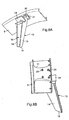
- the support arm (or flame holder arm) 13, illustrated in FIGS. 2A and 2B, is made in the form of a one-piece structure made of composite material resistant to high temperatures.
- This composite material is preferably ceramic matrix.
- the one-piece structure is made from a fiber preform, in particular silicon carbide or carbon, in which a matrix is infiltrated. ceramic in the liquid or gaseous phase.
- CERASEP ® 410-12 it is possible for example to realize the monobloc structure with CERASEP ® 410-12.
- the use of a composite material is particularly advantageous because it allows a saving in weight (compared to metallic materials) and an increase in the service life, in particular in the presence of high operating temperatures.
- the one-piece structure comprises two substantially symmetrical walls 14 and 15 which meet on one longitudinal side so as to define a groove 16 whose profile, in a transverse section, is substantially V-shaped.
- These two walls 14 and 15 comprise first end portions 17 which are joined and shaped so as to define a foot 18 which is preferably in the form of a bevel so as to promote the flow of the primary flow.
- each wall 14 and 15 also has a second end portion 19, opposite the foot 18 and shaped so as to define at least one flange 20, 21 intended to be secured to the outer annular casing 5, as will be seen more Referring to FIG. 7, to allow this securing, for example by means of bolts, each flange 20, 21 comprises at least one through orifice 22, and preferably at least two, as illustrated in FIG. 2B.
- each wall 14, 15 preferably comprises a notch (or notch) 23 at a chosen level (identical for both).
- notch 23 defines a housing in which can be placed a burner ring support 24, as shown in Figure 3.
- the level at which the indentations 23 are formed is chosen depending on where the burner ring is to be placed. In the illustrated example, they are made near the second ends 19 so that the burner ring is placed in the duct 4 dedicated to the secondary flow. But, alternatively, they could be placed in a central portion of the walls 14 and 15, or even in the vicinity of the foot 18, so that the burner ring is placed in the conduit 10 dedicated to the primary flow.
- the burner ring support 24 has a central portion 25, defining a V-shaped open groove on both sides, and extended rearward, substantially perpendicularly, by two lateral portions 26 secured to internal faces of the two walls 14 and 15, in the vicinity of their notches 23.
- This fastening can for example be done using rivets 27.
- the burner ring support 24 is for example made of a metallic material when it is located in the "cold” secondary zone. But, it can also be made of a composite material, especially when installed in the "hot” primary zone.
- the burner ring in the burner ring support 24, it preferably comprises at least one through-orifice 28 on each of the two wings which constitute its central portion 25.
- the spacing between the two walls 14 and 15 may not be constant from the foot 18 to the second end portions 19.
- the V-shaped profile of the groove 16 may vary.
- the spacing here increases substantially continuously from the foot 18 to the second end portions 19.
- the thickness of the two walls 14 and 15 may not be constant from the foot 18 to the second end portions 19. part of the support arm 13, subject to greater stresses than the other parts, is reinforced. Thus, an excess thickness at the second end portions 19 may enable them to better withstand the thermal stresses and the vein pressure forces.
- An afterburner 7 of a turbofan engine comprises at least three support arms 13 of the type of those described above, and more preferably at least four. In some turbojets, the number of arms may be nine (9).
- FIGS. 7, 8A and 8B describe an example of joining a support arm 13 to the outer annular casing 5 of an afterburner 7.
- each support arm 13 is secured by its flanges 20 and 21 to the outer annular casing 5.
- connection is effected directly on the outer annular casing 5, in a "cold" environment (typically less than about 200 ° C.), this does not generate any problem of differential thermal expansion between the support arm 13 and the annular casing. external 5. It can therefore use particularly simple fastening means (or fastening), such as bolts 29.
- bolts 29 two bolts 29 (and at least one) can be used to immobilize each flange 20, 21.
- each arm extends substantially in a radial direction relative to the axis of rotation of the turbine 9, which is also the axis of revolution of the outer casing 5 and inner casings 6 and 11. It is recalled that the Here is meant by inner casing 6 and inner casing 11 what the skilled person calls respectively the confluence sheet and the exhaust cone.
- the afterburner device 7 may comprise a thermal protection jacket 32, interposed between the first internal annular casing 6 (or confluence plate) and the outer annular casing 5, and defining with this last an afterburner channel 33 in which circulates at least a portion of the secondary flow.
- This thermal protection jacket 32 is generally a corrugated and multi-perforated sheet intended to contain the afterburner gases (just like the walls of a main chamber), and to protect the outer annular casing 5 of the hot stream.
- the notches 23 of the walls 14 and 15 of each support arm 13 are formed at a level chosen so that the burner ring support 24 is at least partly framed. by the intermediate annular casing 32 and the first inner annular casing 6 (or confluence sheet).
- each flange 20, 21 it is possible to place a reinforcing and / or protective counterplate 30 below the outer face (opposite to the outer casing 5) of each flange 20, 21 so that it is interposed between the latter and the nut or nuts.
- This counter plate 30 is preferably made of metal.
- V-shaped profile and the shape of the foot 18 of each support arm 13 are chosen so as to optimize the flow of the primary (arrow F1 of FIG. 7) and secondary (arrow F2 of FIG. 7) and thus to obtain an aerodynamism corresponding to the expected performances.
- a support arm 13 may possibly house in its groove 16 an internal carburizing device.
- the latter can withstand high temperatures, so it is not necessary to equip it with an internal ventilation device for cooling the part of its leading edge that is swept by the primary flow.
Landscapes
- Engineering & Computer Science (AREA)
- Chemical & Material Sciences (AREA)
- Combustion & Propulsion (AREA)
- Mechanical Engineering (AREA)
- General Engineering & Computer Science (AREA)
- Structures Of Non-Positive Displacement Pumps (AREA)
- Exhaust Gas After Treatment (AREA)
- Nozzles For Spraying Of Liquid Fuel (AREA)
- Organic Low-Molecular-Weight Compounds And Preparation Thereof (AREA)
Claims (14)
- Tragarm (13) für einen Nachbrenner (7) einer Doppelstrom-Strahlturbine, wobei die Vorrichtung (7) ein erstes (6) und ein zweites (11) ringförmiges inneres Gehäuse aufweist, die einen Kanal (10) für einen Primärstrom definieren, und ein ringförmiges äußeres Gehäuse (5) aufweist, der mit dem ersten ringförmigen inneren Gehäuse (6) einen Kanal (4) für einen Sekundärstrom definiert, wobei er eine Monoblockstruktur aus einem Verbundmaterial aufweist, das zwei verbundene Seitenwände (14, 15) aufweist, die derart angelenkt sind, dass sie einen Hals (16) definieren, der ein Profil im Wesentlichen in Form eines V aufweist, und dadurch gekennzeichnet, dass er erste Endabschnitte (17), die verbunden sind und derart ausgebildet sind, dass sie einen Fuß (18) bilden, und zweite Endabschnitte (19) aufweist, die derart ausgebildet sind, dass sie jeweils wenigstens einen Flansch (20, 21) definieren, der geeignet ist, mit dem äußeren Gehäuse (5) verbunden zu werden.
- Arm nach Anspruch 1, dadurch gekennzeichnet, dass die Seitenwände (14, 15) eine nichtkonstante Beabstandung zwischen den ersten (17) und zweiten (19) Endabschnitten aufweist, derart, dass das Profil des Halses (16) variiert.
- Arm nach Anspruch 2, dadurch gekennzeichnet, dass die Beabstandung im Wesentlichen kontinuierlich variiert, unter Anwachsen der ersten Endabschnitte (17) zu den zweiten Endabschnitten (19), derart, dass das Profil des Halses (16) im Wesentlichen kontinuierlich variiert.
- Arm nach einem der Ansprüche 1 bis 3, dadurch gekennzeichnet, dass die Seitenwände (14, 15) eine nichtkonstante Dicke zwischen den ersten (17) und zweiten (19) Endabschnitten aufweisen.
- Arm nach Anspruch 4, dadurch gekennzeichnet, dass die Seitenwände (14, 15) eine Dicke aufweisen, die auf der Höhe der zweiten Endabschnitte (19) größer ist.
- Arm nach einem der Ansprüche 1 bis 5, dadurch gekennzeichnet, dass die Seitenwände (14, 15) jeweils auf einem selben ausgewählten Niveau, einen Einschnitt (23) aufweisen, derart, dass sie eine Aufnahme definieren, die in der Lage ist, ein Lager des Brennerrings (24) aufzunehmen.
- Arm nach Anspruch 6, dadurch gekennzeichnet, dass das Brennerringlager (24) mit den Seitenwänden (14, 15) in der Nähe der Einschnitte (23) verbunden ist.
- Arm nach Anspruch 6 oder 7, dadurch gekennzeichnet, dass das Brennerringlager (24) mit den Seitenwänden (14, 15) durch Nieten (27) verbunden ist.
- Arm nach einem der Ansprüche 6 bis 8, dadurch gekennzeichnet, dass die Einschnitte (23) in einer Zone eines Bereichs der Seitenwände (14, 15) ausgebildet sind, die dazu dient, in den Kanal des Sekundärstromes gesetzt zu werden.
- Arm nach Anspruch 9, dadurch gekennzeichnet, dass die Zone dazu dient, in die Nähe des ersten inneren Gehäuses (6) gesetzt zu werden.
- Arm nach einem der Ansprüche 1 bis 10, dadurch gekennzeichnet, dass jeder Flansch (20, 21) in der Lage ist, mit dem äußeren Gehäuse (5) durch wenigstens eine Schraube (29) verbunden zu werden, mit Zwischensetzen einer Gegenplatte (30) auf der Seite des Flansches, der dem Sekundärstrom ausgesetzt ist.
- Arm nach einem der Ansprüche 1 bis 11, dadurch gekennzeichnet, dass die Monoblockstruktur aus einem Verbundmaterial mit keramischer Matrix verwirklicht ist.
- Nachbrennervorrichtung (7) für eine Doppelstrom-Strahlturbine, mit einem ersten (6) und einem zweiten (11) inneren ringförmigen Gehäuse, die einen Kanal (10) für einen Primärstrom definieren, und einem äußeren ringförmigen Gehäuse (5), das mit dem ersten inneren ringförmigen Gehäuse (6) einen Kanal (4) für einen Sekundärstrom definiert, dadurch gekennzeichnet, dass sie wenigstens drei Tragarme (13) nach einem der vorangehenden Ansprüche aufweist, die mit dem externen ringförmigen Gehäuse (5) verbunden sind.
- Vorrichtung nach Anspruch 13, dadurch gekennzeichnet, dass sie in dem Sekundärstromkanal (4) eine Wärmeschutzschürze (32) aufweist, die mit dem äußeren ringförmigen Gehäuse (5) einen Nachbrennerkanal (33) für einen Teil des Sekundärstromes bildet, und dass das Brennerringlager (24) eines jeden Tragarms (13) auf eine Höhe zwischen der Höhe der Wärmeschutzschürze (32) und der Höhe des ersten inneren ringförmigen Gehäuses (6) gesetzt ist.
Applications Claiming Priority (2)
| Application Number | Priority Date | Filing Date | Title |
|---|---|---|---|
| FR0400651A FR2865502B1 (fr) | 2004-01-23 | 2004-01-23 | Bras monobloc accroche-flammes pour un dispositif de post combustion d'un turboreacteur a double flux |
| FR0400651 | 2004-01-23 |
Publications (2)
| Publication Number | Publication Date |
|---|---|
| EP1557553A1 EP1557553A1 (de) | 2005-07-27 |
| EP1557553B1 true EP1557553B1 (de) | 2006-08-23 |
Family
ID=34630667
Family Applications (1)
| Application Number | Title | Priority Date | Filing Date |
|---|---|---|---|
| EP05290134A Expired - Lifetime EP1557553B1 (de) | 2004-01-23 | 2005-01-21 | Einblockarm für eine Nachverbrennungsvorrichtung eines Triebwerkes mit Doppelströmung |
Country Status (9)
| Country | Link |
|---|---|
| US (1) | US7168253B1 (de) |
| EP (1) | EP1557553B1 (de) |
| JP (1) | JP2005207421A (de) |
| CA (1) | CA2494433C (de) |
| DE (1) | DE602005000074T2 (de) |
| ES (1) | ES2270407T3 (de) |
| FR (1) | FR2865502B1 (de) |
| RU (1) | RU2309279C2 (de) |
| UA (1) | UA83345C2 (de) |
Families Citing this family (16)
| Publication number | Priority date | Publication date | Assignee | Title |
|---|---|---|---|---|
| FR2884564B1 (fr) | 2005-04-15 | 2011-01-14 | Snecma Moteurs | Procede d'assemblage de deux pieces dont l'une au moins est en materiau composite, insert pour la realisation de l'assemblage |
| FR2894326B1 (fr) | 2005-12-05 | 2008-01-11 | Snecma Sa | Dispositif de fixation d'un bras accroche-flammes sur un carter de post-combustion et equipement comportant un tel dispositif |
| FR2902838B1 (fr) | 2006-06-26 | 2013-03-15 | Snecma | Cone d'echappement pour la canalisation d'une veine de gaz a l'aval d'une turbine |
| FR2926338B1 (fr) * | 2008-01-11 | 2010-03-05 | Snecma | Support forme a partir d'une tole |
| FR2935464B1 (fr) * | 2008-09-01 | 2018-10-26 | Safran Aircraft Engines | Dispositif de fixation d'un bras accroche flammes sur un carter de post-combustion. |
| FR2935753B1 (fr) * | 2008-09-08 | 2011-07-01 | Snecma Propulsion Solide | Liaisons souples a butee pour fixation de piece en cmc |
| JP5375433B2 (ja) * | 2009-08-21 | 2013-12-25 | 株式会社Ihi | アフタバーナ及び航空機エンジン |
| FR2950416B1 (fr) * | 2009-09-23 | 2012-04-20 | Snecma | Dispositif accroche-flammes comprenant un support de bras et un ecran de protection thermique monoblocs |
| FR2981700B1 (fr) * | 2011-10-24 | 2016-08-26 | Snecma Propulsion Solide | Dispositif de fixation d'une piece creuse |
| JP2013181473A (ja) * | 2012-03-02 | 2013-09-12 | Ihi Corp | アフタバーナ及び航空機エンジン |
| US9879862B2 (en) | 2013-03-08 | 2018-01-30 | Rolls-Royce North American Technologies, Inc. | Gas turbine engine afterburner |
| JP6340918B2 (ja) * | 2014-05-23 | 2018-06-13 | 株式会社Ihi | 推力増強装置 |
| FR3032519B1 (fr) * | 2015-02-10 | 2017-02-24 | Herakles | Dispositif accroche-flamme |
| EP3147456A1 (de) | 2015-09-28 | 2017-03-29 | Siemens Aktiengesellschaft | Turbinenschaufel mit nut im kronenboden |
| WO2017074345A1 (en) * | 2015-10-28 | 2017-05-04 | Siemens Energy, Inc. | Combustion system with injector assembly including aerodynamically-shaped body and/or ejection orifices |
| CN112901368A (zh) * | 2021-03-23 | 2021-06-04 | 中国航发沈阳发动机研究所 | 航空涡扇发动机偏离匹配设计时冷却气调节方法及系统 |
Family Cites Families (12)
| Publication number | Priority date | Publication date | Assignee | Title |
|---|---|---|---|---|
| FR2587455B1 (fr) * | 1985-09-18 | 1987-10-30 | Snecma | Procede de fabrication d'un anneau bruleur en materiau composite et anneau bruleur realise suivant ledit procede |
| RU2028487C1 (ru) * | 1988-02-18 | 1995-02-09 | Научно-производственное объединение им.А.М.Люльки | Форсажная камера сгорания |
| US4901527A (en) * | 1988-02-18 | 1990-02-20 | General Electric Company | Low turbulence flame holder mount |
| US5022805A (en) * | 1989-02-16 | 1991-06-11 | Rolls-Royce Incorporated | Cantilever mounting system for structural members having dissimilar coefficients of thermal expansion |
| US5103638A (en) * | 1990-01-29 | 1992-04-14 | Rolls-Royce Inc. | Mounting arrangement |
| US5090198A (en) * | 1990-05-04 | 1992-02-25 | Rolls-Royce Inc. & Rolls-Royce Plc | Mounting assembly |
| US5367873A (en) * | 1991-06-24 | 1994-11-29 | United Technologies Corporation | One-piece flameholder |
| FR2687734B1 (fr) * | 1992-02-26 | 1994-08-26 | Snecma | Dispositif accroche-flammes a geometrie variable destine a etre utilise dans le dispositif post-combustion d'une turbomachine. |
| FR2699227B1 (fr) * | 1992-12-16 | 1995-01-13 | Snecma | Ensemble monobloc de post-combustion d'une turbine à gaz. |
| FR2699226B1 (fr) * | 1992-12-16 | 1995-01-13 | Snecma | Ensemble de post-combustion d'une turbine à gaz. |
| US5497616A (en) * | 1994-11-16 | 1996-03-12 | Rolls-Royce Inc. | High temperature mounting for stress relief of a dovetail |
| RU2209992C1 (ru) * | 2002-03-06 | 2003-08-10 | Государственное унитарное предприятие Тушинское машиностроительное конструкторское бюро "Союз" - дочернее предприятие Федерального государственного унитарного предприятия "Российской самолётостроительной корпорации "МиГ" | Форсажная камера двухконтурного турбореактивного двигателя |
-
2004
- 2004-01-23 FR FR0400651A patent/FR2865502B1/fr not_active Expired - Fee Related
- 2004-12-30 US US11/024,732 patent/US7168253B1/en not_active Expired - Lifetime
-
2005
- 2005-01-18 JP JP2005009947A patent/JP2005207421A/ja active Pending
- 2005-01-20 CA CA002494433A patent/CA2494433C/fr not_active Expired - Lifetime
- 2005-01-21 ES ES05290134T patent/ES2270407T3/es not_active Expired - Lifetime
- 2005-01-21 DE DE602005000074T patent/DE602005000074T2/de not_active Expired - Lifetime
- 2005-01-21 RU RU2005101452/06A patent/RU2309279C2/ru active
- 2005-01-21 EP EP05290134A patent/EP1557553B1/de not_active Expired - Lifetime
- 2005-01-21 UA UAA200500573A patent/UA83345C2/uk unknown
Also Published As
| Publication number | Publication date |
|---|---|
| CA2494433C (fr) | 2009-09-15 |
| DE602005000074D1 (de) | 2006-10-05 |
| ES2270407T3 (es) | 2007-04-01 |
| CA2494433A1 (fr) | 2005-07-23 |
| US7168253B1 (en) | 2007-01-30 |
| FR2865502B1 (fr) | 2006-03-03 |
| RU2309279C2 (ru) | 2007-10-27 |
| US20070039327A1 (en) | 2007-02-22 |
| JP2005207421A (ja) | 2005-08-04 |
| RU2005101452A (ru) | 2006-07-10 |
| FR2865502A1 (fr) | 2005-07-29 |
| DE602005000074T2 (de) | 2007-03-01 |
| EP1557553A1 (de) | 2005-07-27 |
| UA83345C2 (uk) | 2008-07-10 |
Similar Documents
| Publication | Publication Date | Title |
|---|---|---|
| EP1557553B1 (de) | Einblockarm für eine Nachverbrennungsvorrichtung eines Triebwerkes mit Doppelströmung | |
| EP2321514B1 (de) | Flexible anschlagverbindungen zur befestigung eines teils aus cmc | |
| EP1607582B1 (de) | Aufhängung einer Gasturbinenbrennkammer mit integriertem Turbinenleitapparat | |
| EP1818615B1 (de) | Ringförmige Brennkammer eines Turbotriebwerks | |
| EP2142787B1 (de) | Mehrstromige gasturbine mit einer abgasvorrichtung | |
| CA2782661C (fr) | Chambre de combustion pour turbomachine | |
| EP1607682B1 (de) | Gasturbine | |
| FR3131597A1 (fr) | Turbine pour turbomachine | |
| FR2956875A1 (fr) | Aube allegee pour turbomachine, carter comportant une pluralite d'une telle aube et turbomachine comportant au moins un tel carter | |
| CA2908363C (fr) | Disque de soufflante pour un turboreacteur et turboreacteur | |
| EP1950497B1 (de) | Verteilerkammer für gasturbinenmotor, brennkammer und gasturbinenmotor, der diese umfasst | |
| FR2699227A1 (fr) | Ensemble monobloc de post-combustion d'une turbine à gaz. | |
| EP4251925B1 (de) | Verbrennungsmodul für eine turbomaschine | |
| WO2023131759A1 (fr) | Turbine pour turbomachine | |
| FR3054827B1 (fr) | Element de fixation pour nacelle de turboreacteur d’aeronef et ensemble propulsif comportant un tel element | |
| FR2965843A1 (fr) | Rotor pour turbomachine | |
| WO2022096821A1 (fr) | Fixation d'un cône d'éjection dans une tuyère de turbomachine | |
| EP2888452B1 (de) | Gasturbinentriebwerk mit einem teil aus faserverbundwerkstoff und einem metallischen teil, beide teile verbunden mit einer weichen befestigung | |
| FR2992018A1 (fr) | Montage d'un distributeur de turbine haute-pression sur une chambre a combustion d'une turbomachine | |
| EP2499341B1 (de) | Anordnung für ein flugzeugturbinentriebwerk | |
| FR2943404A1 (fr) | Fond de chambre de combustion definissant en partie une fente pour le passage d'un film d'air de refroissement | |
| EP4486986A1 (de) | Ausstosskonus für ein flugzeugturbinentriebwerk | |
| WO2025061774A1 (fr) | Carter de compresseur basse pression d'une turbomachine d'aéronef | |
| FR3111964A1 (fr) | Assemblage d’une pièce de chambre de combustion par recouvrement par une autre pièce | |
| FR2993316A1 (fr) | Support d'habillage d'un carter de turbomachine en composite estampe et fixe sur la peau du carter |
Legal Events
| Date | Code | Title | Description |
|---|---|---|---|
| PUAI | Public reference made under article 153(3) epc to a published international application that has entered the european phase |
Free format text: ORIGINAL CODE: 0009012 |
|
| AK | Designated contracting states |
Kind code of ref document: A1 Designated state(s): AT BE BG CH CY CZ DE DK EE ES FI FR GB GR HU IE IS IT LI LT LU MC NL PL PT RO SE SI SK TR |
|
| AX | Request for extension of the european patent |
Extension state: AL BA HR LV MK YU |
|
| RAP1 | Party data changed (applicant data changed or rights of an application transferred) |
Owner name: SNECMA |
|
| 17P | Request for examination filed |
Effective date: 20051219 |
|
| GRAP | Despatch of communication of intention to grant a patent |
Free format text: ORIGINAL CODE: EPIDOSNIGR1 |
|
| AKX | Designation fees paid |
Designated state(s): DE ES FR GB IT SE |
|
| RIN1 | Information on inventor provided before grant (corrected) |
Inventor name: TOUCHAUD, STEPHANE HENRI GUY Inventor name: HABAROU, GEORGES Inventor name: PANCOU, THIERRY GABRIEL Inventor name: CONETE, ERIC Inventor name: BLANCHARD, STEPHANE PIERRE GUILLAUME Inventor name: CAMY, PIERRE |
|
| GRAS | Grant fee paid |
Free format text: ORIGINAL CODE: EPIDOSNIGR3 |
|
| GRAA | (expected) grant |
Free format text: ORIGINAL CODE: 0009210 |
|
| AK | Designated contracting states |
Kind code of ref document: B1 Designated state(s): DE ES FR GB IT SE |
|
| PG25 | Lapsed in a contracting state [announced via postgrant information from national office to epo] |
Ref country code: IT Free format text: LAPSE BECAUSE OF FAILURE TO SUBMIT A TRANSLATION OF THE DESCRIPTION OR TO PAY THE FEE WITHIN THE PRESCRIBED TIME-LIMIT;WARNING: LAPSES OF ITALIAN PATENTS WITH EFFECTIVE DATE BEFORE 2007 MAY HAVE OCCURRED AT ANY TIME BEFORE 2007. THE CORRECT EFFECTIVE DATE MAY BE DIFFERENT FROM THE ONE RECORDED. Effective date: 20060823 |
|
| REG | Reference to a national code |
Ref country code: GB Ref legal event code: FG4D Free format text: NOT ENGLISH |
|
| REF | Corresponds to: |
Ref document number: 602005000074 Country of ref document: DE Date of ref document: 20061005 Kind code of ref document: P |
|
| REG | Reference to a national code |
Ref country code: SE Ref legal event code: TRGR |
|
| GBT | Gb: translation of ep patent filed (gb section 77(6)(a)/1977) |
Effective date: 20061122 |
|
| REG | Reference to a national code |
Ref country code: ES Ref legal event code: FG2A Ref document number: 2270407 Country of ref document: ES Kind code of ref document: T3 |
|
| PLBE | No opposition filed within time limit |
Free format text: ORIGINAL CODE: 0009261 |
|
| STAA | Information on the status of an ep patent application or granted ep patent |
Free format text: STATUS: NO OPPOSITION FILED WITHIN TIME LIMIT |
|
| 26N | No opposition filed |
Effective date: 20070524 |
|
| PGRI | Patent reinstated in contracting state [announced from national office to epo] |
Ref country code: IT Effective date: 20090301 |
|
| PGFP | Annual fee paid to national office [announced via postgrant information from national office to epo] |
Ref country code: ES Payment date: 20130109 Year of fee payment: 9 |
|
| REG | Reference to a national code |
Ref country code: ES Ref legal event code: FD2A Effective date: 20150401 |
|
| PG25 | Lapsed in a contracting state [announced via postgrant information from national office to epo] |
Ref country code: ES Free format text: LAPSE BECAUSE OF NON-PAYMENT OF DUE FEES Effective date: 20140122 |
|
| REG | Reference to a national code |
Ref country code: FR Ref legal event code: PLFP Year of fee payment: 12 |
|
| REG | Reference to a national code |
Ref country code: FR Ref legal event code: PLFP Year of fee payment: 13 |
|
| REG | Reference to a national code |
Ref country code: FR Ref legal event code: PLFP Year of fee payment: 14 |
|
| REG | Reference to a national code |
Ref country code: FR Ref legal event code: CD Owner name: SAFRAN AIRCRAFT ENGINES Effective date: 20170719 |
|
| PGFP | Annual fee paid to national office [announced via postgrant information from national office to epo] |
Ref country code: GB Payment date: 20231219 Year of fee payment: 20 |
|
| PGFP | Annual fee paid to national office [announced via postgrant information from national office to epo] |
Ref country code: SE Payment date: 20231219 Year of fee payment: 20 Ref country code: FR Payment date: 20231219 Year of fee payment: 20 |
|
| PGFP | Annual fee paid to national office [announced via postgrant information from national office to epo] |
Ref country code: DE Payment date: 20231219 Year of fee payment: 20 |
|
| PGFP | Annual fee paid to national office [announced via postgrant information from national office to epo] |
Ref country code: IT Payment date: 20240102 Year of fee payment: 20 |
|
| REG | Reference to a national code |
Ref country code: DE Ref legal event code: R071 Ref document number: 602005000074 Country of ref document: DE |
|
| REG | Reference to a national code |
Ref country code: GB Ref legal event code: PE20 Expiry date: 20250120 |
|
| REG | Reference to a national code |
Ref country code: SE Ref legal event code: EUG |
|
| PG25 | Lapsed in a contracting state [announced via postgrant information from national office to epo] |
Ref country code: GB Free format text: LAPSE BECAUSE OF EXPIRATION OF PROTECTION Effective date: 20250120 |