EP4251925B1 - Verbrennungsmodul für eine turbomaschine - Google Patents
Verbrennungsmodul für eine turbomaschine Download PDFInfo
- Publication number
- EP4251925B1 EP4251925B1 EP21839600.0A EP21839600A EP4251925B1 EP 4251925 B1 EP4251925 B1 EP 4251925B1 EP 21839600 A EP21839600 A EP 21839600A EP 4251925 B1 EP4251925 B1 EP 4251925B1
- Authority
- EP
- European Patent Office
- Prior art keywords
- combustion
- annular
- chamber
- envelope
- casing
- Prior art date
- Legal status (The legal status is an assumption and is not a legal conclusion. Google has not performed a legal analysis and makes no representation as to the accuracy of the status listed.)
- Active
Links
Images


Classifications
-
- F—MECHANICAL ENGINEERING; LIGHTING; HEATING; WEAPONS; BLASTING
- F23—COMBUSTION APPARATUS; COMBUSTION PROCESSES
- F23R—GENERATING COMBUSTION PRODUCTS OF HIGH PRESSURE OR HIGH VELOCITY, e.g. GAS-TURBINE COMBUSTION CHAMBERS
- F23R3/00—Continuous combustion chambers using liquid or gaseous fuel
-
- F—MECHANICAL ENGINEERING; LIGHTING; HEATING; WEAPONS; BLASTING
- F23—COMBUSTION APPARATUS; COMBUSTION PROCESSES
- F23R—GENERATING COMBUSTION PRODUCTS OF HIGH PRESSURE OR HIGH VELOCITY, e.g. GAS-TURBINE COMBUSTION CHAMBERS
- F23R3/00—Continuous combustion chambers using liquid or gaseous fuel
- F23R3/42—Continuous combustion chambers using liquid or gaseous fuel characterised by the arrangement or form of the flame tubes or combustion chambers
- F23R3/50—Combustion chambers comprising an annular flame tube within an annular casing
-
- F—MECHANICAL ENGINEERING; LIGHTING; HEATING; WEAPONS; BLASTING
- F23—COMBUSTION APPARATUS; COMBUSTION PROCESSES
- F23R—GENERATING COMBUSTION PRODUCTS OF HIGH PRESSURE OR HIGH VELOCITY, e.g. GAS-TURBINE COMBUSTION CHAMBERS
- F23R3/00—Continuous combustion chambers using liquid or gaseous fuel
- F23R3/007—Continuous combustion chambers using liquid or gaseous fuel constructed mainly of ceramic components
-
- F—MECHANICAL ENGINEERING; LIGHTING; HEATING; WEAPONS; BLASTING
- F23—COMBUSTION APPARATUS; COMBUSTION PROCESSES
- F23R—GENERATING COMBUSTION PRODUCTS OF HIGH PRESSURE OR HIGH VELOCITY, e.g. GAS-TURBINE COMBUSTION CHAMBERS
- F23R3/00—Continuous combustion chambers using liquid or gaseous fuel
- F23R3/42—Continuous combustion chambers using liquid or gaseous fuel characterised by the arrangement or form of the flame tubes or combustion chambers
- F23R3/54—Reverse-flow combustion chambers
-
- F—MECHANICAL ENGINEERING; LIGHTING; HEATING; WEAPONS; BLASTING
- F23—COMBUSTION APPARATUS; COMBUSTION PROCESSES
- F23R—GENERATING COMBUSTION PRODUCTS OF HIGH PRESSURE OR HIGH VELOCITY, e.g. GAS-TURBINE COMBUSTION CHAMBERS
- F23R3/00—Continuous combustion chambers using liquid or gaseous fuel
- F23R3/42—Continuous combustion chambers using liquid or gaseous fuel characterised by the arrangement or form of the flame tubes or combustion chambers
- F23R3/60—Support structures; Attaching or mounting means
-
- F—MECHANICAL ENGINEERING; LIGHTING; HEATING; WEAPONS; BLASTING
- F23—COMBUSTION APPARATUS; COMBUSTION PROCESSES
- F23R—GENERATING COMBUSTION PRODUCTS OF HIGH PRESSURE OR HIGH VELOCITY, e.g. GAS-TURBINE COMBUSTION CHAMBERS
- F23R2900/00—Special features of, or arrangements for continuous combustion chambers; Combustion processes therefor
- F23R2900/00017—Assembling combustion chamber liners or subparts
-
- Y—GENERAL TAGGING OF NEW TECHNOLOGICAL DEVELOPMENTS; GENERAL TAGGING OF CROSS-SECTIONAL TECHNOLOGIES SPANNING OVER SEVERAL SECTIONS OF THE IPC; TECHNICAL SUBJECTS COVERED BY FORMER USPC CROSS-REFERENCE ART COLLECTIONS [XRACs] AND DIGESTS
- Y02—TECHNOLOGIES OR APPLICATIONS FOR MITIGATION OR ADAPTATION AGAINST CLIMATE CHANGE
- Y02T—CLIMATE CHANGE MITIGATION TECHNOLOGIES RELATED TO TRANSPORTATION
- Y02T50/00—Aeronautics or air transport
- Y02T50/60—Efficient propulsion technologies, e.g. for aircraft
Definitions
- the present invention relates to a combustion module for a turbomachine, and more particularly, to the configuration and mounting of the ceramic matrix composite (CMC) material walls of a combustion chamber of the combustion module.
- CMC ceramic matrix composite
- the state of the art includes, in particular, the documents US-A1-2018/238232 , JP-B2-3331826 And US-A1-2010/139283 .
- a turbomachine in particular of an aircraft, comprises a gas generator comprising in particular one or more compressors, for example low pressure and high pressure, arranged upstream of a combustion module.
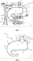
- a combustion module 1 of a turbomachine 10 in particular an aircraft, has a longitudinal axis X which can be confused with a longitudinal axis of the turbomachine 10.
- the module 1 comprises a combustion chamber 2 which has an annular shape.
- the chamber 2 extends around the axis X and is surrounded by an annular casing 3 which also extends around the axis X.
- the chamber 2 is delimited by coaxial inner 4 and outer 5 annular walls joined by a chamber bottom 6.
- the outer wall 5 is fixed to the casing 3 which carries an annular row of fuel injectors 7 so as to supply the chamber 2 with fuel.
- each injector 7 passes through an axis A which is perpendicular to the axis X.
- FIG 1 illustrates a return chamber 2, in which the chamber bottom 6 is located downstream.
- the inner and outer annular walls 4, 5 of the chamber 2 extend radially towards the inside of the module 1 (relative to the X axis) by a turnaround 4a, 5a to bring the combustion gases from the chamber 2 towards a turbine distributor 94.
- the turnaround 4a, 5a comprises an internal elbow 4a connected to the inner wall 4 and an external elbow 5a connected to the outer wall 5.
- a direct combustion chamber i.e. with normal flow, comprises a chamber bottom located upstream and an outlet which is located downstream and opens into the distributor of a turbine of the turbomachine.
- FIG. 1 illustrates a return combustion chamber in which the chamber bottom is located on the downstream side and the reversal provided at the chamber outlet allows the combustion gases to be redirected into the turbine distributor.
- combustion chamber architecture In the design and integration of a combustion module, it is possible to separate the combustion chamber architecture into several parts, in particular to facilitate the manufacture and/or operability of the combustion module. This can lead to assembly problems of the different parts manufactured separately in an extremely thermally and mechanically constrained environment.
- the combustion chamber is usually made of a metallic material that allows the separately manufactured parts to be assembled by mechanical connection (such as bolts), welding or brazing.
- the combustion chamber can also be made of a composite material (such as a ceramic matrix composite CMC) comprising assemblies of parts with so-called “hybrid” connections, namely a part made of metallic material linked to a part made of composite material able to support differential expansions, and connections between two parts made of composite material.
- a composite material such as a ceramic matrix composite CMC
- composite materials are particularly advantageous in the field of turbomachinery because these materials, relatively light, have better temperature resistance, which makes it possible to save cooling air or to operate at higher temperatures.
- an assembly of parts made of CMC material is generally carried out by bolt-type fasteners.
- This bolt assembly is relatively bulky and can be complex to set up in the environment of the combustion module which presents mechanical, thermomechanical and chemical constraints. For example, it is necessary in particular to ensure reliable tightening at all operating points and to provide an anti-rotation device for the bolt.
- the combustion module further comprises anti-disengagement devices configured to keep the annular edges in axial support on each other, these devices being carried by the combustion chamber and/or by the casing.
- the combustion module further comprises fuel injectors carried by the casing and engaged in orifices of one of the casings, said anti-disengagement devices being formed by washers which are mounted around the injectors and tightened radially against this casing, and which comprise tabs configured to cooperate by support and/or attachment with the other of the casings.
- the anti-disengagement devices of the combustion module according to the invention have several advantages. In particular, they make it possible to position and assemble the CMC material envelopes (forming the annular walls and the chamber bottom) together in a simple and effective manner, while preventing them from becoming separated during operation.
- An anti-disconnection device prevents the connection from being dismantled in cases where the pressure difference is not sufficient to keep the elements in contact, such as when the turbine is stopped.
- the anti-disengagement devices can be formed by both washers and stop members, as described according to at least one of the particularities of the invention.
- the invention also relates to a turbomachine, in particular for an aircraft, comprising a combustion module as previously described.
- the invention also relates to an aircraft not covered by the invention, comprising a fuselage and powered by at least one turbomachine comprising a combustion module as previously described.
- the terms “longitudinal” and “axial” qualify the orientation of structural elements extending in the direction of a longitudinal axis, such as a longitudinal axis of a combustion module.
- the terms “radial” or “vertical” qualify an orientation of structural elements extending in a direction perpendicular to the longitudinal axis.
- the terms “inner” and “outer”, and “internal” and “external” are used in reference to a positioning relative to the longitudinal axis.
- a structural element extending along the longitudinal axis has an inner face facing the longitudinal axis and an outer surface, opposite its inner surface.
- upstream and “downstream” are defined in relation to the direction of gas flow in a turbomachine.
- FIGS. 2 to 8 represent several embodiments of a combustion module 1 according to the invention.
- turbomachine 10 in particular an aircraft turbomachine, such as a turbojet or a turboprop.
- the turbomachine 10 typically comprises a compressor module comprising at least one compressor, a turbine module comprising at least one turbine and the combustion module 1 interposed between the compression and turbine modules.
- the combustion module 1 comprises an annular casing 3 extending around a longitudinal axis X and surrounding an annular combustion chamber 2.
- This axis X can be confused with a longitudinal axis, such as an axis of rotation of a rotor, of the turbomachine 10.
- Chamber 2 and housing 3 extend around the X axis. Chamber 2 may extend parallel or inclined to the X axis.
- FIG. 2 schematically illustrates the chamber 2 comprising an internal annular wall 4 and an external annular wall 5. These walls 4, 5 are coaxial and connected to each other by an annular chamber bottom 6.
- This chamber 2 is reverse flow.
- the chamber bottom 6 is arranged on the downstream side of the turbomachine and the chamber 2 opens on the upstream side of the turbomachine towards the turbine module.
- the chamber bottom 6 is arranged on the upstream side of the turbomachine.
- the chamber bottom 6 may comprise a transverse annular wall passing substantially through a first plane P1 which is perpendicular to the axis X.
- the outer wall 5 is fixed to the casing 3 which carries an annular row of fuel injectors 7 distributed angularly around the axis X so as to supply the chamber 2 with fuel.
- the outer wall 5 comprises an annular row of orifices 54 extending around the axis X.
- Each of the orifices 54 has an internal diameter D 54 .
- Each of the orifices 54 comprises a peripheral edge 56.
- Each of the orifices 54 is capable of receiving a fuel injector 7.
- the injector 7 passes through an axis A which is substantially perpendicular to the axis X.
- the orifices 54 and the injectors 7 could be inclined or parallel to the axis X.
- the chamber 2 is made of ceramic matrix composite material CMC.
- the internal and external walls 4, 5 and the chamber bottom 6 are formed by at least two annular envelopes 50, 60 made of ceramic matrix composite material CMC.
- the internal annular wall 4 and the chamber bottom 6 are formed in a single piece by a first envelope 60.
- the first envelope 60 has a general shape of an inverted “S”, in which one of the two loops corresponds substantially to the chamber bottom and the other of the loops corresponds substantially to the inner wall 4 and the inner elbow 4a of the chamber.
- the outer annular wall 5 is formed in one piece by a second casing 50.
- the second casing 50 has a general “C” shape, in which an upper part corresponds substantially to the outer wall 5 and a lower part corresponding substantially to the outer elbow 5a.
- first and second envelopes 50, 60 are connected to each other on the downstream side. These envelopes 50, 60 are extended on the upstream side by a turn-over 4a, 5a which extends radially inwards (relative to the axis X) of the module 1, to open into a distributor 94 of the turbine module.
- the first and second envelopes 50, 60 each comprise, respectively, an annular edge 62 called internal, and an annular edge 52 called external.
- the annular edges 52, 62 fit into each other, in particular at the connection between the external wall 5 and the chamber bottom 6.
- the internal edge 62 bears radially (or substantially radially) on the external edge 52.
- radial support means a bearing force exerted by the internal edge 62 along a transverse plane (relative to the axis X) on a cylindrical surface of the external edge 52.
- substantially radial support means a bearing force exerted by the internal edge 62 along an inclined plane (relative to the axis X) on a frustoconical surface of the external edge 52, in particular when the chamber 2 is inclined relative to the axis X.
- edge 62 of the first envelope 60 may comprise a scalloped shape (not illustrated in the figures), in particular near the injectors 7. This in particular makes it possible to axially compact the chamber 2.
- the scalloped shape may be produced by a series of projecting or re-entrant arc segments, such as undulations.
- the combustion module 1 comprises anti-disengagement devices 8 carried by the chamber 2 (illustrated in the Figures 2 to 7 ) or carried by the housing 3 of module 1 (illustrated on the figure 8 ).
- Each of the devices 8 is used to hold the annular edges 52, 62 in axial (or substantially axial) support on each other, or with limited play. In this way, a separation of the casings 50, 60 from the chamber 2 during operation and when stopped (and consequently of the connection between the external wall 5 and the chamber bottom 6) is prevented, while allowing simple and effective assembly and disassembly of the devices 8 in the available space of the combustion module 1.
- axial support means a support force or contact exerted by the outer edge 52 along the X axis on a cylindrical surface of the inner edge 62.
- substantially axial support means a support force or contact exerted by the outer edge 52 along an inclined plane (relative to the X axis) on a frustoconical surface of the inner edge 62, in particular when the chamber 2 is inclined relative to the X axis; or conversely, a support force exerted by the inner edge 62 along an inclined plane (relative to the X axis) on a frustoconical surface of the outer edge 52.
- the anti-disengagement devices 8 can be installed on the chamber 2.
- the devices 8 are mounted around the fuel injectors 7.
- the devices 8 are each formed of a washer 86 which is configured to be attached around the injector 7.
- the washer 86 therefore has a generally annular and flat shape.
- This washer 86 comprises a first central opening 860 and legs 862.
- the opening 860 has an internal diameter D 860 .
- the washer 86 may comprise one or more tabs 862.
- the number and dimensions (shape, length, thickness, etc.) of the tabs 862 per washer 86 may vary depending on the dimensions and materials of the parts making up the combustion module 1.
- the washer 86 comprises two legs 862 which are oriented parallel to each other. These legs 862 each have a hook shape.
- the thickness of each washer 86 can determine their degree of participation in maintaining the tightening forces, in particular during the flight phases of the turbomachine.
- the washer 86 may be made of a composite material of the CMC type or of a metal alloy.
- the washer 86 is made of stainless steel, for example of the A286 type.
- the A286 stainless steel has the advantages of being compatible with the thermal environment of the combustion chamber 2, and of having a high coefficient of thermal expansion in order in particular to maintain in an optimized manner the connections between parts in extreme operating temperatures of the combustion module 1.
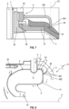
- the washer 86 is configured to be clamped radially (i.e. substantially perpendicular to the X axis) against the second casing 50 of the outer wall 5 by a clamping nut 84 and a sleeve 82.
- the socket 82 has a tubular shape and therefore comprises a second central opening 820 and a barrel 822.
- the second opening 820 has an internal diameter D 820.
- the barrel 822 may comprise an external thread.
- the sleeve 82 also includes an annular collar 824.
- the collar 824 and the barrel 822 may be delimited by a tubular portion 826.
- the annular collar 824 comprises a first flank 824a which has a planar shape and a second flank 824b which has a truncated cone shape.
- the second flank 824b narrows towards the tubular portion 826.
- the truncated cone shape of the second flank 824b of the annular collar 824 of the sleeve 82 can expand. This can cause a displacement relative to the casing 50. This truncated cone shape of the second flank 824b can return a radial displacement relative to an axial displacement, leading to a tightening of the connection between the sleeve 82, the nut 84 and the casing 50.
- the washer 86 can be made of a material having a coefficient of thermal expansion making it possible to compensate for an expansion difference between the casing 50 and the nut 84.
- the collar 824 has an external diameter D 824 which is greater than the external diameters D 826 , D 822 of the tubular part 826 and of the barrel 822.
- the external diameter D 826 of the tubular part 826 is greater than the external diameter D 822 of the barrel 822.
- the sleeve 82 is mounted around the injector 7, in particular through the second opening 820.
- This second opening 820 therefore extends around the axis A of the injector 7.
- the internal diameter D 820 of the second opening 820 of the sleeve is therefore substantially similar to the external diameter D 7 of the injector 7.
- the annular edge 52 of the second casing 50 comprises the orifices 54 in which the injectors 7 are intended to be engaged.
- the edge 52 is mounted around the collar 824 of the sleeve 82, in particular through the orifices 54. This allows the peripheral edge 56 of the orifice 54 to bear on the second flank 824b of the collar 824. In the example of the figure 5 , the peripheral edge 56 rests on the second flank 824b in an inclined position relative to the axes X and A.
- the external diameter D 826 of the tubular part 826 of the sleeve 82 is substantially similar to the internal diameter D 54 of the orifice 54 of the second casing 50.
- the washer 86 is mounted around the sleeve 82, in particular through the first opening 860.
- This first opening 860 also extends around the axis A.
- the internal diameter D 860 of the first opening 860 of the washer is therefore substantially similar to the external diameter D 826 of the tubular part 826 of the sleeve and to the internal diameter D 54 of the orifice 54 of the second casing 50.
- the annular edge 62 of the first casing 60 comprises in the example slots 64 of a shape complementary to the tabs 862 of the washer 86. This allows the hook-shaped tabs 862 to engage in the slots 64 of the first casing 60, as illustrated in the figure 4 .
- the nut 84 is screwed around the barrel 822 of the sleeve 82, in particular through a third opening 840 of the nut 84.
- the third opening 840 has an internal diameter D 840 substantially similar to the external diameter D 822 of the barrel 822 of the sleeve 82.
- This third opening 840 may comprise an internal thread complementary to the external thread of the barrel 822 of the sleeve 82.
- FIG. 6 illustrates one of the anti-disengagement devices 8 and its assembly according to a second embodiment, in which the anti-disengagement devices 8 can also be installed on the chamber 2.
- the anti-disengagement devices 8 of the second embodiment are distinguished from the devices 8 of the first embodiment by the tabs 862 of the washer 86 and the edge 62 of the first casing 60.
- the legs 862 of the washer 86 have an elongated and curved shape.
- the edge 62 of the first casing 60 comprises a boss 66 passing substantially through a second plane P2.
- This plane P2 is substantially perpendicular to the axis X of the module 1 and located in upstream of the first plane P1 of the chamber bottom 6.
- the edge 62 may comprise an excess thickness of the envelope 60 at the level of the plane P2.
- the legs 862 and the boss 66 have a complementary shape. This allows the legs 862 to be fixed to the boss 66 by direct support, so that the legs 862 tightened radially against the edge 52 are in abutment on the boss 66 of the edge 62. This configuration also therefore makes it possible to maintain the edges 52, 62 of the envelopes 50, 60 in axial support on each other.
- the legs 862 are elongated so that their free and curved ends face the plane P1 corresponding substantially to the transverse wall of the chamber bottom 6. This makes it possible in particular to compensate for an axial displacement of the assembly of the edges 52, 62 during operation of the combustion module 1.
- the elongated shape of the legs 862 makes it possible to provide flexibility to the connection between the legs 862 and the boss 66.
- the assembly between the casings 50, 60 (of the walls 5, 6 and of the chamber bottom 6), is rigid in particular with permanent contact between the legs 862 and the boss 66, and with little or no assembly play between the edges 52, 62 of the casings 50, 60.
- This second embodiment has the advantage in particular of avoiding carrying out complex machining on the edge 62 of the first envelope 60.
- FIG 7 illustrates one of the anti-disengagement devices 8 and its assembly according to a third embodiment, in which these devices 8 can also be installed on the chamber 2.
- the anti-disengagement devices 8 of the third embodiment are distinguished from the devices 8 of the first embodiment by the tabs 862 of the washer 86 and the edge 62 of the first casing 60.
- the edge 62 of the first envelope 60 comprises at least one shoulder 68, so as to form an axial support surface for one of the legs 862 of the washer 86.
- the shoulder 68 is made on an excess thickness of the envelope 60 located substantially at the level of the plane P2.
- the legs 862 and the shoulders 68 may have a complementary shape.
- the tab 862 comprises a curved free end 864 engaging in the shoulder 68 of the edge 62.
- the tabs 862 are fixed in the shoulders 68 also by direct axial support.
- this configuration also allows the edges 52, 62 to be held on each other.
- This third embodiment is an alternative solution that is simple to produce and implement to prevent the connection of the envelopes 50, 60 from becoming detached.
- the anti-disengagement devices 8 can be carried on the casing 3.
- the devices 8 and the casing 3 are monobloc (i.e. made from one material).
- these devices 8 are stop members formed in projection on the casing 3. These stop members can comprise free ends 880 capable of coming into abutment on the chamber 2, in particular on the chamber bottom 6. This configuration makes it possible to prevent any movement of the chamber bottom 6 relative to the external wall 5.
- stop members can be made of a rigid or flexible material.
- the stop members are made of a composite, metallic, or metallic alloy material.
- the stop members can be made of the same material as the casing 3 but with a first thickness reduced relative to a second thickness of the casing 3. This makes it possible in particular to make the stop members flexible, while being able to exert sufficient support on the chamber 2 to keep the edges 52, 62 in axial support on each other.
- a mounting clearance and/or a clearance for compensating for expansions during operation can be added between the stop members and the chamber bottom.
- These mounting and expansion clearances can vary depending on the materials or dimensions (such as thickness) used for the casings and the stop members. For example, this mounting clearance and/or clearance for compensating for expansions is of the order of a millimeter.
- the stop members and the casing 3 can be made in one piece (i.e. from the same material).
- the stop members are in the form of arms 88.
- the arm 88 has an elongated shape in the direction of the chamber bottom 6.
- the end 880 of the arm 88 can be inclined relative to the axis X.
- This end 880 comprises a bearing surface 882 on the chamber bottom 6.
- the support surface 882 passes substantially through the first plane P1.
- the casing 3 may comprise between three and eight arms 88 distributed circumferentially around the axis X, so that an air flow coming from a diffuser 92 of the compressor module can circulate in the module 1.
- the free ends 880 of the arms 88 may comprise a thermal protection coating. This makes it possible in particular to lower the temperature of the arms 88.
- This coating may be associated with a material different from the material used to produce the stop members. This makes it possible to promote chemical or thermal compatibility between the stop members and the chamber.
- This fourth embodiment of the devices 8 has the advantage in particular of promoting hyperstaticism (i.e. making immobile) of the edges 52, 62 nested one on the other, and thus limiting movements and/or deformations.
- the stop members of the embodiment of the figure 8 are combined with the washers of at least one of the embodiments of the Figures 2 to 7 .
- the devices 8 are formed both by washers 86 and stop members.
- the proposed solutions are simple, efficient and economical to produce and assemble on a turbomachine and an aircraft, while ensuring the safe assembly and disassembly of the combustion chamber (produced by composite material parts) in a turbomachine.
Landscapes
- Engineering & Computer Science (AREA)
- Chemical & Material Sciences (AREA)
- Combustion & Propulsion (AREA)
- Mechanical Engineering (AREA)
- General Engineering & Computer Science (AREA)
- Ceramic Engineering (AREA)
- Turbine Rotor Nozzle Sealing (AREA)
- Structures Of Non-Positive Displacement Pumps (AREA)
Claims (10)
- Verbrennungsmodul (1) für eine Turbomaschine, insbesondere eines Luftfahrzeugs (10), umfassend:- ein ringförmiges Gehäuse (3), das sich um eine Längsachse (X) erstreckt,- eine ringförmige Brennkammer (2), die sich im Inneren des Gehäuses (3) befindet und koaxiale ringförmige Wände, eine innere (4) bzw. eine äußere (5), umfasst, die über einen ringförmigen Kammerboden (6) miteinander verbunden sind, wobei die Wände (4, 5) und der Kammerboden (6) durch mindestens zwei ringförmige Schalen (50, 60) gebildet sind, die aus einem Verbundmaterial mit Keramikmatrix hergestellt sind und die ringförmige Ränder (52, 62) umfassen, die ineinander verschachtelt sind und in axialer Auflage aufeinander aufliegen,dadurch gekennzeichnet, dass das Modul (1) weiter Entschachtelungsverhinderungsvorrichtungen (8) umfasst, die konfiguriert sind, um die ringförmigen Ränder (52, 62) aufeinander aufliegend halten, wobei diese Vorrichtungen (8) von der Brennkammer (2) und/oder dem Gehäuse (3) gestützt werden,und dadurch, dass das Modul (1) weiter Kraftstoffeinspritzer (7) umfasst, die von dem Gehäuse (3) gestützt werden und in Öffnungen (54) einer der Schalen (50) eingreifen, wobei die Entschachtelungsverhinderungsvorrichtungen (8) Scheiben (86) umfassen, die um die Einspritzer (7) herum angebracht und radial gegen diese Schale (50) gedrückt sind und die Laschen (862) umfassen, die konfiguriert sind, um durch Auflage und/oder Ankoppelung mit der anderen der Schalen (60) zusammenzuwirken.
- Verbrennungsmodul nach Anspruch 1, dadurch gekennzeichnet, dass es eine erste Schale (60), die die Innenwand (4) und den Kammerboden (6) definiert, und eine zweite Schale (50), die die Außenwand (5) definiert, umfasst, wobei sich die Ränder (52, 62) an der Verbindungsstelle der Außenwand (5) mit dem Kammerboden (6) befinden.
- Verbrennungsmodul nach Anspruch 1 oder 2, dadurch gekennzeichnet, dass der ringförmige Rand (62) der ersten Schale (60) eine festonierte Form umfasst.
- Verbrennungsmodul nach einem der Ansprüche 1 bis 3, dadurch gekennzeichnet, dass jede der Scheiben (86) zwischen der Schale (50) und einer Klemmmutter (84) der Scheibe gegen die Schale (50) eingefügt ist.
- Verbrennungsmodul nach Anspruch 4, dadurch gekennzeichnet, dass die Mutter (84) an einem Schaft (822) einer rohrförmigen Fassung (82) aufgeschraubt ist, die um den Einspritzer (7) herum angebracht ist, wobei diese Fassung (82) einen ringförmigen Kranz (824) zur Auflage auf einem Umfangsrand (52) der Öffnung (54), in die der Einspritzer (7) eingreift, umfasst.
- Verbrennungsmodul nach einem der Ansprüche 1 bis 5, dadurch gekennzeichnet, dass jede der Scheiben (86) zwei Laschen (862) umfasst, die vorzugsweise in im Wesentlichen parallelen Richtungen ausgerichtet sind.
- Verbrennungsmodul nach einem der Ansprüche 1 bis 6, dadurch gekennzeichnet, dass die Laschen (862) jeweils eine zum Rand (62) der anderen Schale (60) komplementäre Form aufweisen und/oder jeweils eine Hakenform aufweisen, um in einen Spalt (62) dieser anderen Schale (60) zum Eingriff zu kommen.
- Verbrennungsmodul nach einem der Ansprüche 1 bis 7, dadurch gekennzeichnet, dass jede der Scheiben (86) aus rostfreiem Stahl, zum Beispiel vom Typ A286, hergestellt ist.
- Verbrennungsmodul nach einem der Ansprüche 1 bis 8, dadurch gekennzeichnet, dass die Brennkammer (2) mit umgekehrter Strömung ist.
- Turbomaschine (10), insbesondere eines Luftfahrzeugs, umfassend ein Verbrennungsmodul (1) nach einem der vorstehenden Ansprüche.
Priority Applications (1)
| Application Number | Priority Date | Filing Date | Title |
|---|---|---|---|
| EP25150845.3A EP4513091A3 (de) | 2020-11-30 | 2021-11-26 | Verbrennungsmodul für eine turbomaschine |
Applications Claiming Priority (2)
| Application Number | Priority Date | Filing Date | Title |
|---|---|---|---|
| FR2012392A FR3116862B1 (fr) | 2020-11-30 | 2020-11-30 | Module de combustion pour une turbomachine |
| PCT/FR2021/052113 WO2022112726A1 (fr) | 2020-11-30 | 2021-11-26 | Module de combustion pour une turbomachine |
Related Child Applications (2)
| Application Number | Title | Priority Date | Filing Date |
|---|---|---|---|
| EP25150845.3A Division EP4513091A3 (de) | 2020-11-30 | 2021-11-26 | Verbrennungsmodul für eine turbomaschine |
| EP25150845.3A Division-Into EP4513091A3 (de) | 2020-11-30 | 2021-11-26 | Verbrennungsmodul für eine turbomaschine |
Publications (2)
| Publication Number | Publication Date |
|---|---|
| EP4251925A1 EP4251925A1 (de) | 2023-10-04 |
| EP4251925B1 true EP4251925B1 (de) | 2025-02-19 |
Family
ID=74871507
Family Applications (2)
| Application Number | Title | Priority Date | Filing Date |
|---|---|---|---|
| EP25150845.3A Pending EP4513091A3 (de) | 2020-11-30 | 2021-11-26 | Verbrennungsmodul für eine turbomaschine |
| EP21839600.0A Active EP4251925B1 (de) | 2020-11-30 | 2021-11-26 | Verbrennungsmodul für eine turbomaschine |
Family Applications Before (1)
| Application Number | Title | Priority Date | Filing Date |
|---|---|---|---|
| EP25150845.3A Pending EP4513091A3 (de) | 2020-11-30 | 2021-11-26 | Verbrennungsmodul für eine turbomaschine |
Country Status (5)
| Country | Link |
|---|---|
| US (2) | US12092335B2 (de) |
| EP (2) | EP4513091A3 (de) |
| CN (2) | CN116490729B (de) |
| FR (2) | FR3116862B1 (de) |
| WO (1) | WO2022112726A1 (de) |
Families Citing this family (2)
| Publication number | Priority date | Publication date | Assignee | Title |
|---|---|---|---|---|
| US12535214B2 (en) | 2024-04-19 | 2026-01-27 | Rtx Corporation | Attaching powerplant structures together using fuel injector bolts |
| US12480657B1 (en) * | 2025-04-29 | 2025-11-25 | General Electric Company | Gas turbine engine and fuel nozzle therefor |
Family Cites Families (16)
| Publication number | Priority date | Publication date | Assignee | Title |
|---|---|---|---|---|
| JPS5659131A (en) * | 1979-10-19 | 1981-05-22 | Nissan Motor Co Ltd | Gas turbine combustor |
| JP3331826B2 (ja) * | 1995-08-16 | 2002-10-07 | 日産自動車株式会社 | ガスタービンの燃焼器 |
| US6339923B1 (en) * | 1998-10-09 | 2002-01-22 | General Electric Company | Fuel air mixer for a radial dome in a gas turbine engine combustor |
| US6314716B1 (en) * | 1998-12-18 | 2001-11-13 | Solar Turbines Incorporated | Serial cooling of a combustor for a gas turbine engine |
| FR2871846B1 (fr) * | 2004-06-17 | 2006-09-29 | Snecma Moteurs Sa | Chambre de combustion en cmc de turbine a gaz supportee dans un carter metallique par des organes de liaison en cmc |
| US7673460B2 (en) * | 2005-06-07 | 2010-03-09 | Snecma | System of attaching an injection system to a turbojet combustion chamber base |
| US8327648B2 (en) * | 2008-12-09 | 2012-12-11 | Pratt & Whitney Canada Corp. | Combustor liner with integrated anti-rotation and removal feature |
| US8745989B2 (en) * | 2009-04-09 | 2014-06-10 | Pratt & Whitney Canada Corp. | Reverse flow ceramic matrix composite combustor |
| US8739547B2 (en) * | 2011-06-23 | 2014-06-03 | United Technologies Corporation | Gas turbine engine joint having a metallic member, a CMC member, and a ceramic key |
| US9612017B2 (en) * | 2014-06-05 | 2017-04-04 | Rolls-Royce North American Technologies, Inc. | Combustor with tiled liner |
| US20160047549A1 (en) * | 2014-08-15 | 2016-02-18 | Rolls-Royce Corporation | Ceramic matrix composite components with inserts |
| US9976746B2 (en) * | 2015-09-02 | 2018-05-22 | General Electric Company | Combustor assembly for a turbine engine |
| US10385776B2 (en) * | 2017-02-23 | 2019-08-20 | General Electric Company | Methods for assembling a unitary flow path structure |
| US11255547B2 (en) * | 2018-10-15 | 2022-02-22 | Raytheon Technologies Corporation | Combustor liner attachment assembly for gas turbine engine |
| US11112119B2 (en) * | 2018-10-25 | 2021-09-07 | General Electric Company | Combustor assembly for a turbo machine |
| GB2598782A (en) * | 2020-09-14 | 2022-03-16 | Rolls Royce Plc | Combustor arrangement |
-
2020
- 2020-11-30 FR FR2012392A patent/FR3116862B1/fr active Active
-
2021
- 2021-11-26 EP EP25150845.3A patent/EP4513091A3/de active Pending
- 2021-11-26 US US18/254,485 patent/US12092335B2/en active Active
- 2021-11-26 EP EP21839600.0A patent/EP4251925B1/de active Active
- 2021-11-26 CN CN202180079498.3A patent/CN116490729B/zh active Active
- 2021-11-26 CN CN202511853995.0A patent/CN121520615A/zh active Pending
- 2021-11-26 WO PCT/FR2021/052113 patent/WO2022112726A1/fr not_active Ceased
- 2021-12-06 FR FR2113023A patent/FR3117152B1/fr active Active
-
2024
- 2024-08-08 US US18/798,542 patent/US20240401812A1/en active Pending
Also Published As
| Publication number | Publication date |
|---|---|
| WO2022112726A1 (fr) | 2022-06-02 |
| US20240401812A1 (en) | 2024-12-05 |
| EP4513091A2 (de) | 2025-02-26 |
| EP4251925A1 (de) | 2023-10-04 |
| US12092335B2 (en) | 2024-09-17 |
| FR3116862A1 (fr) | 2022-06-03 |
| FR3116862B1 (fr) | 2022-12-23 |
| CN121520615A (zh) | 2026-02-13 |
| CN116490729B (zh) | 2025-12-30 |
| FR3117152B1 (fr) | 2024-01-19 |
| CN116490729A (zh) | 2023-07-25 |
| FR3117152A1 (fr) | 2022-06-10 |
| US20240053016A1 (en) | 2024-02-15 |
| EP4513091A3 (de) | 2025-03-26 |
Similar Documents
| Publication | Publication Date | Title |
|---|---|---|
| EP1607582B1 (de) | Aufhängung einer Gasturbinenbrennkammer mit integriertem Turbinenleitapparat | |
| EP2142787B1 (de) | Mehrstromige gasturbine mit einer abgasvorrichtung | |
| WO2009118478A1 (fr) | Chambre de combustion de turbomachine | |
| CA2712669C (fr) | Diffuseur de turbomachine comportant des voiles annulaires echancres | |
| EP3781793B1 (de) | Keramischer leitschaufelring zum kraftaufnahme | |
| EP4251925B1 (de) | Verbrennungsmodul für eine turbomaschine | |
| EP1557553B1 (de) | Einblockarm für eine Nachverbrennungsvorrichtung eines Triebwerkes mit Doppelströmung | |
| EP3575689B1 (de) | Gasverbrennungsmodul eines turbotriebwerks mit anschlag am brennkammerboden | |
| EP1777460B2 (de) | Fastening of a combustion chamber inside its housing | |
| FR3005693A1 (fr) | Turbomachine d'aeronef a double flux comprenant une virole inter-veine a maintien aval simplifie | |
| EP4226034B1 (de) | Dichtungsanordnung für einen turbinenausstosskegel | |
| WO2022096820A1 (fr) | Fixation d'un cône d'éjection dans une tuyère de turbomachine | |
| WO2022096821A1 (fr) | Fixation d'un cône d'éjection dans une tuyère de turbomachine | |
| EP4493811B1 (de) | Anordnung für einen abgaskonus in einer turbomaschinendüse | |
| EP4326972A1 (de) | An einem querträger montierte turbinenringanordnung | |
| WO2021209711A1 (fr) | Bougie pour chambre de combustion monobloc | |
| FR3111964A1 (fr) | Assemblage d’une pièce de chambre de combustion par recouvrement par une autre pièce | |
| FR3144858A1 (fr) | Système d’injection de carburant pour turbomachine | |
| FR2952702A1 (fr) | Guidage d'une bougie d'allumage dans une chambre de combustion | |
| FR3075271A1 (fr) | Ensemble pour la fixation entre elements a coefficients de dilatation thermique differents |
Legal Events
| Date | Code | Title | Description |
|---|---|---|---|
| STAA | Information on the status of an ep patent application or granted ep patent |
Free format text: STATUS: UNKNOWN |
|
| STAA | Information on the status of an ep patent application or granted ep patent |
Free format text: STATUS: THE INTERNATIONAL PUBLICATION HAS BEEN MADE |
|
| PUAI | Public reference made under article 153(3) epc to a published international application that has entered the european phase |
Free format text: ORIGINAL CODE: 0009012 |
|
| STAA | Information on the status of an ep patent application or granted ep patent |
Free format text: STATUS: REQUEST FOR EXAMINATION WAS MADE |
|
| 17P | Request for examination filed |
Effective date: 20230623 |
|
| AK | Designated contracting states |
Kind code of ref document: A1 Designated state(s): AL AT BE BG CH CY CZ DE DK EE ES FI FR GB GR HR HU IE IS IT LI LT LU LV MC MK MT NL NO PL PT RO RS SE SI SK SM TR |
|
| DAV | Request for validation of the european patent (deleted) | ||
| DAX | Request for extension of the european patent (deleted) | ||
| GRAP | Despatch of communication of intention to grant a patent |
Free format text: ORIGINAL CODE: EPIDOSNIGR1 |
|
| STAA | Information on the status of an ep patent application or granted ep patent |
Free format text: STATUS: GRANT OF PATENT IS INTENDED |
|
| INTG | Intention to grant announced |
Effective date: 20240701 |
|
| GRAJ | Information related to disapproval of communication of intention to grant by the applicant or resumption of examination proceedings by the epo deleted |
Free format text: ORIGINAL CODE: EPIDOSDIGR1 |
|
| STAA | Information on the status of an ep patent application or granted ep patent |
Free format text: STATUS: REQUEST FOR EXAMINATION WAS MADE |
|
| GRAP | Despatch of communication of intention to grant a patent |
Free format text: ORIGINAL CODE: EPIDOSNIGR1 |
|
| STAA | Information on the status of an ep patent application or granted ep patent |
Free format text: STATUS: GRANT OF PATENT IS INTENDED |
|
| INTC | Intention to grant announced (deleted) | ||
| INTG | Intention to grant announced |
Effective date: 20240911 |
|
| GRAS | Grant fee paid |
Free format text: ORIGINAL CODE: EPIDOSNIGR3 |
|
| GRAA | (expected) grant |
Free format text: ORIGINAL CODE: 0009210 |
|
| STAA | Information on the status of an ep patent application or granted ep patent |
Free format text: STATUS: THE PATENT HAS BEEN GRANTED |
|
| AK | Designated contracting states |
Kind code of ref document: B1 Designated state(s): AL AT BE BG CH CY CZ DE DK EE ES FI FR GB GR HR HU IE IS IT LI LT LU LV MC MK MT NL NO PL PT RO RS SE SI SK SM TR |
|
| REG | Reference to a national code |
Ref country code: GB Ref legal event code: FG4D Free format text: NOT ENGLISH |
|
| REG | Reference to a national code |
Ref country code: CH Ref legal event code: EP |
|
| REG | Reference to a national code |
Ref country code: DE Ref legal event code: R096 Ref document number: 602021026511 Country of ref document: DE |
|
| REG | Reference to a national code |
Ref country code: IE Ref legal event code: FG4D Free format text: LANGUAGE OF EP DOCUMENT: FRENCH |
|
| REG | Reference to a national code |
Ref country code: NL Ref legal event code: MP Effective date: 20250219 |
|
| PG25 | Lapsed in a contracting state [announced via postgrant information from national office to epo] |
Ref country code: RS Free format text: LAPSE BECAUSE OF FAILURE TO SUBMIT A TRANSLATION OF THE DESCRIPTION OR TO PAY THE FEE WITHIN THE PRESCRIBED TIME-LIMIT Effective date: 20250519 |
|
| PG25 | Lapsed in a contracting state [announced via postgrant information from national office to epo] |
Ref country code: FI Free format text: LAPSE BECAUSE OF FAILURE TO SUBMIT A TRANSLATION OF THE DESCRIPTION OR TO PAY THE FEE WITHIN THE PRESCRIBED TIME-LIMIT Effective date: 20250219 |
|
| PG25 | Lapsed in a contracting state [announced via postgrant information from national office to epo] |
Ref country code: PL Free format text: LAPSE BECAUSE OF FAILURE TO SUBMIT A TRANSLATION OF THE DESCRIPTION OR TO PAY THE FEE WITHIN THE PRESCRIBED TIME-LIMIT Effective date: 20250219 |
|
| PG25 | Lapsed in a contracting state [announced via postgrant information from national office to epo] |
Ref country code: ES Free format text: LAPSE BECAUSE OF FAILURE TO SUBMIT A TRANSLATION OF THE DESCRIPTION OR TO PAY THE FEE WITHIN THE PRESCRIBED TIME-LIMIT Effective date: 20250219 |
|
| REG | Reference to a national code |
Ref country code: LT Ref legal event code: MG9D |
|
| PG25 | Lapsed in a contracting state [announced via postgrant information from national office to epo] |
Ref country code: IS Free format text: LAPSE BECAUSE OF FAILURE TO SUBMIT A TRANSLATION OF THE DESCRIPTION OR TO PAY THE FEE WITHIN THE PRESCRIBED TIME-LIMIT Effective date: 20250619 Ref country code: NO Free format text: LAPSE BECAUSE OF FAILURE TO SUBMIT A TRANSLATION OF THE DESCRIPTION OR TO PAY THE FEE WITHIN THE PRESCRIBED TIME-LIMIT Effective date: 20250519 |
|
| PG25 | Lapsed in a contracting state [announced via postgrant information from national office to epo] |
Ref country code: NL Free format text: LAPSE BECAUSE OF FAILURE TO SUBMIT A TRANSLATION OF THE DESCRIPTION OR TO PAY THE FEE WITHIN THE PRESCRIBED TIME-LIMIT Effective date: 20250219 |
|
| PG25 | Lapsed in a contracting state [announced via postgrant information from national office to epo] |
Ref country code: HR Free format text: LAPSE BECAUSE OF FAILURE TO SUBMIT A TRANSLATION OF THE DESCRIPTION OR TO PAY THE FEE WITHIN THE PRESCRIBED TIME-LIMIT Effective date: 20250219 |
|
| PG25 | Lapsed in a contracting state [announced via postgrant information from national office to epo] |
Ref country code: PT Free format text: LAPSE BECAUSE OF FAILURE TO SUBMIT A TRANSLATION OF THE DESCRIPTION OR TO PAY THE FEE WITHIN THE PRESCRIBED TIME-LIMIT Effective date: 20250620 Ref country code: LV Free format text: LAPSE BECAUSE OF FAILURE TO SUBMIT A TRANSLATION OF THE DESCRIPTION OR TO PAY THE FEE WITHIN THE PRESCRIBED TIME-LIMIT Effective date: 20250219 |
|
| PG25 | Lapsed in a contracting state [announced via postgrant information from national office to epo] |
Ref country code: GR Free format text: LAPSE BECAUSE OF FAILURE TO SUBMIT A TRANSLATION OF THE DESCRIPTION OR TO PAY THE FEE WITHIN THE PRESCRIBED TIME-LIMIT Effective date: 20250520 Ref country code: BG Free format text: LAPSE BECAUSE OF FAILURE TO SUBMIT A TRANSLATION OF THE DESCRIPTION OR TO PAY THE FEE WITHIN THE PRESCRIBED TIME-LIMIT Effective date: 20250219 |
|
| REG | Reference to a national code |
Ref country code: AT Ref legal event code: MK05 Ref document number: 1768565 Country of ref document: AT Kind code of ref document: T Effective date: 20250219 |
|
| PG25 | Lapsed in a contracting state [announced via postgrant information from national office to epo] |
Ref country code: SE Free format text: LAPSE BECAUSE OF FAILURE TO SUBMIT A TRANSLATION OF THE DESCRIPTION OR TO PAY THE FEE WITHIN THE PRESCRIBED TIME-LIMIT Effective date: 20250219 |
|
| PG25 | Lapsed in a contracting state [announced via postgrant information from national office to epo] |
Ref country code: SM Free format text: LAPSE BECAUSE OF FAILURE TO SUBMIT A TRANSLATION OF THE DESCRIPTION OR TO PAY THE FEE WITHIN THE PRESCRIBED TIME-LIMIT Effective date: 20250219 |
|
| PG25 | Lapsed in a contracting state [announced via postgrant information from national office to epo] |
Ref country code: DK Free format text: LAPSE BECAUSE OF FAILURE TO SUBMIT A TRANSLATION OF THE DESCRIPTION OR TO PAY THE FEE WITHIN THE PRESCRIBED TIME-LIMIT Effective date: 20250219 |
|
| PG25 | Lapsed in a contracting state [announced via postgrant information from national office to epo] |
Ref country code: IT Free format text: LAPSE BECAUSE OF FAILURE TO SUBMIT A TRANSLATION OF THE DESCRIPTION OR TO PAY THE FEE WITHIN THE PRESCRIBED TIME-LIMIT Effective date: 20250219 |
|
| PG25 | Lapsed in a contracting state [announced via postgrant information from national office to epo] |
Ref country code: AT Free format text: LAPSE BECAUSE OF FAILURE TO SUBMIT A TRANSLATION OF THE DESCRIPTION OR TO PAY THE FEE WITHIN THE PRESCRIBED TIME-LIMIT Effective date: 20250219 |
|
| PG25 | Lapsed in a contracting state [announced via postgrant information from national office to epo] |
Ref country code: EE Free format text: LAPSE BECAUSE OF FAILURE TO SUBMIT A TRANSLATION OF THE DESCRIPTION OR TO PAY THE FEE WITHIN THE PRESCRIBED TIME-LIMIT Effective date: 20250219 Ref country code: CZ Free format text: LAPSE BECAUSE OF FAILURE TO SUBMIT A TRANSLATION OF THE DESCRIPTION OR TO PAY THE FEE WITHIN THE PRESCRIBED TIME-LIMIT Effective date: 20250219 |
|
| PG25 | Lapsed in a contracting state [announced via postgrant information from national office to epo] |
Ref country code: RO Free format text: LAPSE BECAUSE OF FAILURE TO SUBMIT A TRANSLATION OF THE DESCRIPTION OR TO PAY THE FEE WITHIN THE PRESCRIBED TIME-LIMIT Effective date: 20250219 |
|
| PG25 | Lapsed in a contracting state [announced via postgrant information from national office to epo] |
Ref country code: SK Free format text: LAPSE BECAUSE OF FAILURE TO SUBMIT A TRANSLATION OF THE DESCRIPTION OR TO PAY THE FEE WITHIN THE PRESCRIBED TIME-LIMIT Effective date: 20250219 |
|
| REG | Reference to a national code |
Ref country code: DE Ref legal event code: R097 Ref document number: 602021026511 Country of ref document: DE |
|
| PLBE | No opposition filed within time limit |
Free format text: ORIGINAL CODE: 0009261 |
|
| STAA | Information on the status of an ep patent application or granted ep patent |
Free format text: STATUS: NO OPPOSITION FILED WITHIN TIME LIMIT |
|
| PGFP | Annual fee paid to national office [announced via postgrant information from national office to epo] |
Ref country code: DE Payment date: 20251118 Year of fee payment: 5 |
|
| PGFP | Annual fee paid to national office [announced via postgrant information from national office to epo] |
Ref country code: GB Payment date: 20251125 Year of fee payment: 5 |
|
| PGFP | Annual fee paid to national office [announced via postgrant information from national office to epo] |
Ref country code: FR Payment date: 20251125 Year of fee payment: 5 |
|
| 26N | No opposition filed |
Effective date: 20251120 |