EP1557554B1 - Vorrichtung zum Steuern eines Druckes in einer Kraftstoff-Vorlaufleitung - Google Patents
Vorrichtung zum Steuern eines Druckes in einer Kraftstoff-Vorlaufleitung Download PDFInfo
- Publication number
- EP1557554B1 EP1557554B1 EP04106719A EP04106719A EP1557554B1 EP 1557554 B1 EP1557554 B1 EP 1557554B1 EP 04106719 A EP04106719 A EP 04106719A EP 04106719 A EP04106719 A EP 04106719A EP 1557554 B1 EP1557554 B1 EP 1557554B1
- Authority
- EP
- European Patent Office
- Prior art keywords
- valve
- pressure
- junction
- fuel
- connection
- Prior art date
- Legal status (The legal status is an assumption and is not a legal conclusion. Google has not performed a legal analysis and makes no representation as to the accuracy of the status listed.)
- Expired - Lifetime
Links
Images

Classifications
-
- F—MECHANICAL ENGINEERING; LIGHTING; HEATING; WEAPONS; BLASTING
- F16—ENGINEERING ELEMENTS AND UNITS; GENERAL MEASURES FOR PRODUCING AND MAINTAINING EFFECTIVE FUNCTIONING OF MACHINES OR INSTALLATIONS; THERMAL INSULATION IN GENERAL
- F16K—VALVES; TAPS; COCKS; ACTUATING-FLOATS; DEVICES FOR VENTING OR AERATING
- F16K15/00—Check valves
- F16K15/02—Check valves with guided rigid valve members
- F16K15/04—Check valves with guided rigid valve members shaped as balls
- F16K15/042—Check valves with guided rigid valve members shaped as balls with a plurality of balls
-
- F—MECHANICAL ENGINEERING; LIGHTING; HEATING; WEAPONS; BLASTING
- F02—COMBUSTION ENGINES; HOT-GAS OR COMBUSTION-PRODUCT ENGINE PLANTS
- F02M—SUPPLYING COMBUSTION ENGINES IN GENERAL WITH COMBUSTIBLE MIXTURES OR CONSTITUENTS THEREOF
- F02M37/00—Apparatus or systems for feeding liquid fuel from storage containers to carburettors or fuel-injection apparatus; Arrangements for purifying liquid fuel specially adapted for, or arranged on, internal-combustion engines
- F02M37/04—Feeding by means of driven pumps
- F02M37/08—Feeding by means of driven pumps electrically driven
- F02M37/10—Feeding by means of driven pumps electrically driven submerged in fuel, e.g. in reservoir
- F02M37/106—Feeding by means of driven pumps electrically driven submerged in fuel, e.g. in reservoir the pump being installed in a sub-tank
-
- F—MECHANICAL ENGINEERING; LIGHTING; HEATING; WEAPONS; BLASTING
- F16—ENGINEERING ELEMENTS AND UNITS; GENERAL MEASURES FOR PRODUCING AND MAINTAINING EFFECTIVE FUNCTIONING OF MACHINES OR INSTALLATIONS; THERMAL INSULATION IN GENERAL
- F16K—VALVES; TAPS; COCKS; ACTUATING-FLOATS; DEVICES FOR VENTING OR AERATING
- F16K15/00—Check valves
- F16K15/02—Check valves with guided rigid valve members
- F16K15/025—Check valves with guided rigid valve members the valve being loaded by a spring
- F16K15/026—Check valves with guided rigid valve members the valve being loaded by a spring the valve member being a movable body around which the medium flows when the valve is open
- F16K15/028—Check valves with guided rigid valve members the valve being loaded by a spring the valve member being a movable body around which the medium flows when the valve is open the valve member consisting only of a predominantly disc-shaped flat element
-
- F—MECHANICAL ENGINEERING; LIGHTING; HEATING; WEAPONS; BLASTING
- F16—ENGINEERING ELEMENTS AND UNITS; GENERAL MEASURES FOR PRODUCING AND MAINTAINING EFFECTIVE FUNCTIONING OF MACHINES OR INSTALLATIONS; THERMAL INSULATION IN GENERAL
- F16K—VALVES; TAPS; COCKS; ACTUATING-FLOATS; DEVICES FOR VENTING OR AERATING
- F16K17/00—Safety valves; Equalising valves, e.g. pressure relief valves
- F16K17/02—Safety valves; Equalising valves, e.g. pressure relief valves opening on surplus pressure on one side; closing on insufficient pressure on one side
- F16K17/04—Safety valves; Equalising valves, e.g. pressure relief valves opening on surplus pressure on one side; closing on insufficient pressure on one side spring-loaded
- F16K17/0406—Safety valves; Equalising valves, e.g. pressure relief valves opening on surplus pressure on one side; closing on insufficient pressure on one side spring-loaded in the form of balls
-
- F—MECHANICAL ENGINEERING; LIGHTING; HEATING; WEAPONS; BLASTING
- F16—ENGINEERING ELEMENTS AND UNITS; GENERAL MEASURES FOR PRODUCING AND MAINTAINING EFFECTIVE FUNCTIONING OF MACHINES OR INSTALLATIONS; THERMAL INSULATION IN GENERAL
- F16K—VALVES; TAPS; COCKS; ACTUATING-FLOATS; DEVICES FOR VENTING OR AERATING
- F16K17/00—Safety valves; Equalising valves, e.g. pressure relief valves
- F16K17/02—Safety valves; Equalising valves, e.g. pressure relief valves opening on surplus pressure on one side; closing on insufficient pressure on one side
- F16K17/04—Safety valves; Equalising valves, e.g. pressure relief valves opening on surplus pressure on one side; closing on insufficient pressure on one side spring-loaded
- F16K17/0413—Safety valves; Equalising valves, e.g. pressure relief valves opening on surplus pressure on one side; closing on insufficient pressure on one side spring-loaded in the form of closure plates
-
- F—MECHANICAL ENGINEERING; LIGHTING; HEATING; WEAPONS; BLASTING
- F16—ENGINEERING ELEMENTS AND UNITS; GENERAL MEASURES FOR PRODUCING AND MAINTAINING EFFECTIVE FUNCTIONING OF MACHINES OR INSTALLATIONS; THERMAL INSULATION IN GENERAL
- F16K—VALVES; TAPS; COCKS; ACTUATING-FLOATS; DEVICES FOR VENTING OR AERATING
- F16K17/00—Safety valves; Equalising valves, e.g. pressure relief valves
- F16K17/02—Safety valves; Equalising valves, e.g. pressure relief valves opening on surplus pressure on one side; closing on insufficient pressure on one side
- F16K17/04—Safety valves; Equalising valves, e.g. pressure relief valves opening on surplus pressure on one side; closing on insufficient pressure on one side spring-loaded
- F16K17/044—Safety valves; Equalising valves, e.g. pressure relief valves opening on surplus pressure on one side; closing on insufficient pressure on one side spring-loaded with more than one spring
Definitions
- the invention relates to a device for controlling a pressure in a fuel supply line of a motor vehicle with a provided for connection to the flow line Einströman gleich and provided for the return of fuel in a fuel tank Ausströman gleich and arranged in a connection of the Einströman gleiches with the Ausströman gleich valve ,
- the invention is based on the problem of designing a device of the type mentioned above so that it largely prevents leakage of fuel to the disconnected internal combustion engine.
- a pressure limiting valve which closes the connection of the inflow connection with the outflow connection below a first pressure provided and throttles a flow through the connection above the first pressure
- a shut-off valve which connects the Einströman gleiches with the Ausströman gleich above a second Closes pressure, wherein the first pressure is less than the second pressure
- connection between the flow line is closed below the first pressure and above the second pressure.
- fuel from the flow line can be discharged into the fuel tank, and thus to avoid an increase in the pressure in the flow line by temperature influences when the engine is switched off.
- it is reliably prevented that fuel can escape from the injection nozzle when the internal combustion engine is switched off.
- closing the connection below the first pressure it is ensured that the supply line remains filled with fuel when the internal combustion engine is switched off and a trouble-free restart of the internal combustion engine is possible.
- the closing of the connection above the second pressure allows the normal operation of the internal combustion engine with the pressure provided by the delivery unit in the fuel tank.
- the throttling of the flow in the connection between the first pressure and the second Pressure has the meaning that the second pressure during operation of the conveyor unit is achieved with a designated capacity.
- the device according to the invention requires a particularly low installation effort when the shut-off valve and the pressure relief valve are designed as a structural unit.
- the device according to the invention can be easily assembled for intended pressures when the shut-off valve and the pressure relief valve are arranged in the flow direction of the flow of fuel from the inflow port to the Ausströman gleich one behind the other.
- the device according to the invention requires only a particularly small number of components if the inflow connection and the outflow connection each have a valve seat and a single, movable between the two valve seats valve body is biased against the valve seat of the Einströman gleiches.
- the pressure relief valve and the shut-off valve each have a spring element and a biased against a valve seat valve body.
- the device makes it possible, for example, to supply a suction jet pump in the fuel tank with particularly low structural complexity, when the connection between the valve seat of the pressure limiting valve and the valve seat of the shut-off valve has a connection for a further consumer of fuel.
- a throttling of the flow between the two provided pressures requires according to another advantageous embodiment of the invention, a particularly low structural complexity, if the individual, movable between the valve seats valve body and a valve body between the valve seats leading wall have different cross-sections. As a result, the valve body is in the flow and is pressed with increasing volume flow against the valve seat of the shut-off valve.
- connection between the two valve seats has a channel for flow around the individual valve body between the first pressure and the second pressure.
- This channel is preferably formed by at least one web guiding the valve body.
- the webs can be grouped in a star shape around the radial circumference of the valve body around.
- the device according to the invention is structurally particularly simple if the valve body has a flat disk made of soft material and support disks arranged thereon.
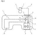
- FIG. 1 1 schematically shows a fuel tank 1 of a motor vehicle with a delivery unit 2 arranged therein for conveying fuel to an internal combustion engine 3.
- the delivery unit 2 has a fuel pump 5 driven by an electric motor 4 and is connected via a supply line 6 to an injection rail 7 of the internal combustion engine 3.
- a check valve 8 and a pressure relief valve 9 are arranged in the flow line 6, .
- the check valve 8 prevents emptying of the supply line 6 with the internal combustion engine 3, while the pressure relief valve 9 opens above a designated pressure and excess fuel via a return line 10 to the conveyor unit 2 returns.
- the supply line 6 is connected via a first fuel line 11 to a device 12 for controlling a pressure in the supply line 6.
- a second fuel line 13 connects the device 12 to the delivery unit 2.
- a third, connected to the device 12 fuel line 14 leads to a suction jet pump 15, which promotes fuel to the delivery unit 2.
- An inflow port 16 of the device 12 is connected to the leading to the flow line 6 fuel line 11.
- the device 12 has an outflow port 17 for connecting the fuel line 13 guided into the delivery unit 2 and a third port 18 for connecting the fuel line 14 leading to the suction jet pump 15.
- FIG. 2 schematically shows a first embodiment of the device 12 from FIG. 1 in which in a connection 19 between the inflow port 16 and the outflow port 17, a check valve 20 and a pressure relief valve 21 are arranged one behind the other.
- the check valve 20 and the pressure relief valve 21 each have a valve seat 22, 23, wherein the valve seats 22, 23 facing each other and between the valve seats 22, 23 a valve body 24 is movably arranged.
- the valve body 24 is biased in the illustrated, pressureless state by a spring element 25 against the valve seat 23 of the pressure relief valve 21.
- the port 18 of leading to the ejector 15 fuel line 14 is made FIG. 1 arranged.
- the device 12 between the valve seats 22, 23 arranged webs 26 for guiding the valve body 24.
- the valve body 24 has a disc 36 made of rubber-elastic material and two support plates 37 made of metal.
- the supply line 6 is filled with fuel.
- the valve body 24 is pushed away from the valve seat 23 of the pressure limiting valve 21, and fuel can flow from the inflow port 16 to the outflow port 17.
- the pressure in the flow line 6 is limited and prevents when switched off the engine 3 at the in FIG. 1 shown injection rail 7 fuel leaks.
- a high volume flow is promoted at high pressure.
- the high pressure and the high flow rate cause the valve body 24 is pressed by the force of the spring element 25 against the valve seat 22 of the check valve 20 and the Outflow connection 17 closes.
- fuel via the third port 18 to the in FIG. 1 shown suction jet pump 15 flow.
- the pressure in the supply line 6 is then of the in FIG. 1 illustrated pressure relief valve 9 and the flow rate of the fuel pump 5 determined.
- FIG. 3 schematically shows a second embodiment of the device 12 from FIG. 1 in the unpressurized state, in which in a connection 27 between the inflow port 16 and the Ausströman gleich 17 a check valve 28 and a pressure relief valve 29 are arranged one behind the other, wherein the check valve 28 is disposed closer to the Einströman gleich 16 than the pressure relief valve 29.
- the check valve 28 and the Pressure relief valve 29 each have a biased by a spring element 30, 31 valve body 32, 33 and a valve seat 34, 35.
- This device 12 has different from the FIG. 2 no connection for leading to the ejector 15 fuel line 14. However, the control of the flow from the inflow port 16 to the Ausströman gleich 17 happens as to the device 12 after FIG. 2 described.
Landscapes
- Engineering & Computer Science (AREA)
- General Engineering & Computer Science (AREA)
- Mechanical Engineering (AREA)
- Chemical & Material Sciences (AREA)
- Combustion & Propulsion (AREA)
- Fuel-Injection Apparatus (AREA)
Description
- Die Erfindung betrifft eine Vorrichtung zum Steuern eines Druckes in einer Kraftstoff-Vorlaufleitung eines Kraftfahrzeuges mit einem zur Verbindung mit der Vorlaufleitung vorgesehenen Einströmanschluss und mit einem zur Rückführung von Kraftstoff in einen Kraftstoffbehälter vorgesehenen Ausströmanschluss und mit einem in einer Verbindung des Einströmanschlusses mit dem Ausströmanschluss angeordneten Ventil.
- Zur Begrenzung eines in einer Vorlaufleitung vorgesehenen Druckes sind Druckbegrenzungsventile bekannt geworden, welche oberhalb eines vorgesehenen Druckes öffnen und überschüssigen Kraftstoff in den Kraftstoffbehälter zurückführen. Damit wird der Maximaldruck, welcher der Brennkraftmaschine zugeführt wird, begrenzt.
- Bei heutigen Kraftfahrzeugen stellt sich jedoch das Problem, dass nach Abschalten der Brennkraftmaschine Kraftstoff aus einer Einspritzdüse der Brennkraftmaschine austreten kann. Dieser Kraftstoff kann wegen eines im Kraftstoffbehälter angeordneten Rückschlagventils nicht in den Kraftstoffbehälter zurückströmen. Insbesondere wenn die Brennkraftmaschine bei kalter Witterung abgestellt wird, steigt mit steigender Temperatur der Druck in der Vorlaufleitung, und Kraftstoff tritt an der Einspritzdüse aus. Der Druck in der Vorlaufleitung kann dabei von 0 bar bis zu 3 bar ansteigen. Dies ist insbesondere bei künftigen Kraftfahrzeugen ohne Schadstoffausstoß - so genannte zero emmission vehicle - nicht mehr tragbar.
- Aus der
JP 11280930 JP 08100727 - Der Erfindung liegt das Problem zugrunde, eine Vorrichtung der Eingangs genannten Art so zu gestalten, dass sie ein Austreten von Kraftstoff an der abgeschalteten Brennkraftmaschine weitgehend verhindert.
- Dieses Problem wird erfindungsgemäß gelöst durch ein Druckbegrenzungsventil, welches die Verbindung des Einströmanschlusses mit dem Ausströmanschluss unterhalb eines vorgesehenen ersten Druckes verschließt und eine Strömung durch die Verbindung oberhalb des ersten Druckes drosselt, und ein Absperrventil, welches die Verbindung des Einströmanschlusses mit dem Ausströmanschluss oberhalb eines zweiten Druckes verschließt, wobei der erste Druck kleiner ist als der zweite Druck.
- Durch diese Gestaltung ist die Verbindung zwischen der Vorlaufleitung unterhalb des ersten Druckes und oberhalb des zweiten Druckes verschlossen. Zwischen dem ersten Druck und dem zweiten Druck vermag Kraftstoff aus der Vorlaufleitung in den Kraftstoffbehälter abgeführt zu werden, und damit bei abgeschalteter Brennkraftmaschine ein Ansteigen des Druckes in der Vorlaufleitung durch Temperatureinflüsse zu vermeiden. Hierdurch wird zuverlässig verhindert, dass Kraftstoff bei abgeschalteter Brennkraftmaschine aus der Einspritzdüse austreten kann. Durch das Schließen der Verbindung unterhalb des ersten Druckes wird sichergestellt, dass die Vorlaufleitung bei abgeschalteter Brennkraftmaschine mit Kraftstoff befüllt bleibt und ein problemloser Neustart der Brennkraftmaschine möglich ist. Das Schließen der Verbindung oberhalb des zweiten Druckes ermöglicht den normalen Betrieb der Brennkraftmaschine mit dem von der Fördereinheit im Kraftstoffbehälter zur Verfügung gestellten Druck. Die Drosselung der Strömung in der Verbindung zwischen dem ersten Druck und dem zweiten Druck hat den Sinn, dass der zweite Druck bei einem Betrieb der Fördereinheit mit einer vorgesehenen Förderleistung auch erreicht wird.
- Die erfindungsgemäße Vorrichtung erfordert einen besonders geringen Montageaufwand, wenn das Absperrventil und das Druckbegrenzungsventil als bauliche Einheit ausgebildet sind.
- Die erfindungsgemäße Vorrichtung lässt sich einfach für vorgesehene Drücke zusammenstellen, wenn das Absperrventil und das Druckbegrenzungsventil in Strömungsrichtung der Strömung des Kraftstoffs von dem Einströmanschluss zu dem Ausströmanschluss hintereinander angeordnet sind.
- Die erfindungsgemäße Vorrichtung erfordert nur eine besonders geringe Anzahl von Bauteilen, wenn der Einströmanschluss und der Ausströmanschluss jeweils einen Ventilsitz aufweisen und ein einzelner, zwischen den beiden Ventilsitzen beweglicher Ventilkörper gegen den Ventilsitz des Einströmanschlusses vorgespannt ist.
- Zur weiteren Vereinfachung der Einstellung der vorgesehenen Drücke trägt es gemäß einer anderen vorteilhaften Weiterbildung der Erfindung bei, wenn das Druckbegrenzungsventil und das Absperrventil jeweils ein Federelement und einen gegen einen Ventilsitz vorgespannten Ventilkörper haben.
- Die Vorrichtung ermöglicht es, mit besonders geringem baulichen Aufwand beispielsweise eine Saugstrahlpumpe im Kraftstoffbehälter zu versorgen, wenn die Verbindung zwischen dem Ventilsitz des Druckbegrenzungsventils und dem Ventilsitz des Absperrventils einen Anschluss für einen weiteren Verbraucher von Kraftstoff aufweist.
- Eine Drosselung der Strömung zwischen den beiden vorgesehenen Drücken erfordert gemäß einer anderen vorteilhaften Weiterbildung der Erfindung einen besonders geringen baulichen Aufwand, wenn der einzelne, zwischen den Ventilsitzen bewegliche Ventilkörper und eine den Ventilkörper zwischen den Ventilsitzen führende Wandung unterschiedliche Querschnitte aufweisen. Hierdurch steht der Ventilkörper in der Strömung und wird mit steigendem Volumenstrom gegen den Ventilsitz des Absperrventils gedrückt.
- Eine zuverlässige Abführung von Kraftstoff bei abgeschalteter Brennkraftmaschine lässt sich auch bei starken Temperaturschwankungen sicherstellen, wenn die Verbindung zwischen den beiden Ventilsitzen einen Kanal zur Umströmung des einzelnen Ventilkörpers zwischen dem ersten Druck und dem zweiten Druck aufweist. Dieser Kanal wird vorzugsweise von zumindest einem den Ventilkörper führenden Steg gebildet. Die Stege können dabei sternförmig um den radialen Umfang des Ventilkörpers herum gruppiert werden.
- Die erfindungsgemäße Vorrichtung gestaltet sich konstruktiv besonders einfach, wenn der Ventilkörper eine ebene, aus weichem Material gefertigte Scheibe und daran angeordnete Stützscheiben aufweist.
- Die Erfindung lässt zahlreiche Ausführungsformen zu. Zur weiteren Verdeutlichung ihres Grundprinzips ist eine davon in der Zeichnung dargestellt und wird nachfolgend beschrieben. Diese zeigt in
- Fig. 1
- schematisch einen Kraftstoffbehälter mit einer erfindungsgemäßen Vorrichtung und einer Brennkraftmaschine,
- Fig. 2
- schematisch eine erste Ausführungsform der erfindungsgemäßen Vorrichtung aus
Figur 1 , - Fig. 3
- schematisch eine zweite Ausführungsform der erfindungsgemäßen Vorrichtung aus
Figur 2 . -
Figur 1 zeigt schematisch einen Kraftstoffbehälter 1 eines Kraftfahrzeuges mit einer darin angeordneten Fördereinheit 2 zur Förderung von Kraftstoff zu einer Brennkraftmaschine 3. Die Fördereinheit 2 hat eine von einem Elektromotor 4 angetriebene Kraftstoffpumpe 5 und ist über eine Vorlaufleitung 6 mit einer Einspritzleiste 7 der Brennkraftmaschine 3 verbunden. In der Vorlaufleitung 6 sind ein Rückschlagventil 8 und ein Druckbegrenzungsventil 9 angeordnet. Das Rückschlagventil 8 verhindert ein Leerlaufen der Vorlaufleitung 6 bei abgestellter Brennkraftmaschine 3, während das Druckbegrenzungsventil 9 oberhalb eines vorgesehenen Druckes öffnet und überschüssigen Kraftstoff über eine Rücklaufleitung 10 zu der Fördereinheit 2 zurückführt. - Weiterhin ist die Vorlaufleitung 6 über eine erste Kraftstoffleitung 11 mit einer Vorrichtung 12 zum Steuern eines Druckes in der Vorlaufleitung 6 verbunden. Eine zweite Kraftstoffleitung 13 verbindet die Vorrichtung 12 mit der Fördereinheit 2. Eine dritte, an der Vorrichtung 12 angeschlossene Kraftstoffleitung 14 führt zu einer Saugstrahlpumpe 15, welche Kraftstoff zu der Fördereinheit 2 fördert. Ein Einströmanschluss 16 der Vorrichtung 12 ist mit der zu der Vorlaufleitung 6 führenden Kraftstoffleitung 11 verbunden. Die Vorrichtung 12 hat einen Ausströmanschluss 17 zum Anschluss der in die Fördereinheit 2 geführten Kraftstoffleitung 13 und einen dritten Anschluss 18 zum Anschluss der zu der Saugstrahlpumpe 15 führenden Kraftstoffleitung 14.
-
Figur 2 zeigt schematisch eine erste Ausführungsform der Vorrichtung 12 ausFigur 1 , bei der in einer Verbindung 19 zwischen dem Einströmanschluss 16 und dem Ausströmanschluss 17 ein Absperrventil 20 und ein Druckbegrenzungsventil 21 hintereinander angeordnet sind. Das Absperrventil 20 und das Druckbegrenzungsventil 21 weisen jeweils einen Ventilsitz 22, 23 auf, wobei die Ventilsitze 22, 23 einander gegenüberstehen und zwischen den Ventilsitzen 22, 23 ein Ventilkörper 24 beweglich angeordnet ist. Der Ventilkörper 24 ist in dem dargestellten, drucklosen Zustand von einem Federelement 25 gegen den Ventilsitz 23 des Druckbegrenzungsventils 21 vorgespannt. Zwischen dem Druckbegrenzungsventil 21 und dem Absperrventil 20 ist der Anschluss 18 der zu der Saugstrahlpumpe 15 führenden Kraftstoffleitung 14 ausFigur 1 angeordnet. Weiterhin hat die Vorrichtung 12 zwischen den Ventilsitzen 22, 23 angeordnete Stege 26 zur Führung des Ventilkörpers 24. Der Ventilkörper 24 hat eine Scheibe 36 aus gummielastischem Material und zwei aus Metall gefertigte Stützscheiben 37. - Bei einem Stillstand der in
Figur 1 dargestellten Fördereinheit 2 ist die Vorlaufleitung 6 mit Kraftstoff befüllt. Wenn bei steigender Temperatur der Druck in der Vorlaufleitung 6 ansteigt, wird der Ventilkörper 24 von dem Ventilsitz 23 des Druckbegrenzungsventils 21 weggedrückt, und Kraftstoff kann von dem Einströmanschluss 16 zu dem Ausströmanschluss 17 überströmen. Damit wird der Druck in der Vorlaufleitung 6 begrenzt und verhindert, dass bei abgeschalteter Brennkraftmaschine 3 an der inFigur 1 dargestellten Einspritzleiste 7 Kraftstoff austritt. Bei einem Betrieb der Fördereinheit 2 wird bei hohem Druck ein hoher Volumenstrom gefördert. Der hohe Druck und der hohe Volumenstrom bewirken, dass der Ventilkörper 24 durch die Kraft des Federelementes 25 gegen den Ventilsitz 22 des Absperrventils 20 gedrückt wird und den Ausströmanschluss 17 verschließt. Gleichzeitig kann Kraftstoff über den dritten Anschluss 18 zu der inFigur 1 dargestellten Saugstrahlpumpe 15 strömen. Der Druck in der Vorlaufleitung 6 wird anschließend von dem inFigur 1 dargestellten Druckbegrenzungsventil 9 und der Förderleistung der Kraftstoffpumpe 5 bestimmt. -
Figur 3 zeigt schematisch eine zweite Ausführungsform der Vorrichtung 12 ausFigur 1 im drucklosen Zustand, bei der in einer Verbindung 27 zwischen dem Einströmanschluss 16 und dem Ausströmanschluss 17 ein Absperrventil 28 und ein Druckbegrenzungsventil 29 hintereinander angeordnet sind, wobei das Absperrventil 28 näher an dem Einströmanschluss 16 angeordnet ist als das Druckbegrenzungsventil 29. Das Absperrventil 28 und das Druckbegrenzungsventil 29 weisen jeweils einen von einem Federelement 30, 31 vorgespannten Ventilkörper 32, 33 und einen Ventilsitz 34, 35 auf. Diese Vorrichtung 12 hat abweichend von der ausFigur 2 keinen Anschluss für die zu der Saugstrahlpumpe 15 führende Kraftstoffleitung 14. Die Steuerung der Strömung von dem Einströmanschluss 16 zu dem Ausströmanschluss 17 geschieht jedoch wie zu der Vorrichtung 12 nachFigur 2 beschrieben.
Claims (9)
- Vorrichtung zum Steuern eines Druckes in einer Kraftstoff-Vorlaufleitung eines Kraftfahrzeuges mit einem zur Verbindung mit der Vorlaufleitung (6) vorgesehenen Einströmanschluss (16) und mit einem Ausströmanschluss (17) und mit einem in einer Verbindung des Einströmanschlusses (16) mit dem Ausströmanschluss (17) angeordneten Ventil, mit einem Druckbegrenzungsventil (21, 29), welches die Verbindung (19, 27) des Einströmanschlusses (16) mit dem Ausströmanschluss (17) unterhalb eines vorgesehenen ersten Drucks verschließt und einem Absperrventil (20, 28), welches die Verbindung (19, 27) des Einströmanschlusses (16) mit dem Ausströmanschluss (17) oberhalb eines zweiten Druckes verschließt, wobei der erste Druck kleiner ist als der zweite Druck, dadurch gekennzeichnet, dass das Druckbegrenzungsventil (21, 29) eine Strömung durch die Verbindung oberhalb des ersten Drucks drosselt und dass der Ausströmanschluss (17) zur Rückführung von Kraftstoff in einen Kraftstoffbehälter vorgesehenen ist.
- Vorrichtung nach Anspruch 1, gekennzeichnet durch, dass das Absperrventil (20, 28) und das Druckbegrenzungsventil (21, 29) als bauliche Einheit ausgebildet sind.
- Vorrichtung nach Anspruch 1 oder 2, gekennzeichnet durch, dass das Absperrventil (20, 28) und das Druckbegrenzungsventil (21, 29) in Strömungsrichtung der Strömung des Kraftstoffs von dem Einströmanschluss (16) zu dem Ausströmanschluss (17) hintereinander angeordnet sind.
- Vorrichtung nach zumindest einem der vorhergehenden Ansprüche, gekennzeichnet durch, dass der Einströmanschluss (16) und der Ausströmanschluss (17) jeweils einen Ventilsitz (22, 23) aufweisen und ein einzelner, zwischen den beiden Ventilsitzen (22, 23) beweglicher Ventilkörper (24) gegen den Ventilsitz (22) des Einströmanschlusses (16) vorgespannt ist.
- Vorrichtung nach zumindest einem der vorhergehenden Ansprüche, gekennzeichnet durch, dass das Druckbegrenzungsventil (29) und das Absperrventil (28) jeweils ein Federelement (30, 31) und einen gegen einen Ventilsitz (34, 35) vorgespannten Ventilkörper (32, 33) haben.
- Vorrichtung nach zumindest einem der vorhergehenden Ansprüche, gekennzeichnet durch, dass die Verbindung (19) zwischen dem Ventilsitz (23) des Druckbegrenzungsventils (21) und dem Ventilsitz (22) des Absperrventils (20) einen Anschluss (18) für einen weiteren Verbraucher von Kraftstoff aufweist.
- Vorrichtung nach Anspruch 4 , gekennzeichnet durch, dass der einzelne, zwischen den Ventilsitzen (22, 23) bewegliche Ventilkörper (24) und eine den Ventilkörper (24) zwischen den Ventilsitzen (22, 23) führende Wandung unterschiedliche Querschnitte aufweisen.
- Vorrichtung nach einen der Ansprüche 4 oder 7 , gekennzeichnet durch, dass die Verbindung (19) zwischen den beiden Ventilsitzen (22, 23) einen Kanal zur Umströmung des einzelnen Ventilkörpers (24) zwischen dem ersten Druck und dem zweiten Druck aufweist.
- Vorrichtung nach einen der Ansprüche 4, 7 oder 8 , gekennzeichnet durch, dass der Ventilkörper (24) eine ebene, aus weichem Material gefertigte Scheibe (36) und daran angeordnete Stützscheiben (37) aufweist.
Applications Claiming Priority (2)
| Application Number | Priority Date | Filing Date | Title |
|---|---|---|---|
| DE102004003113A DE102004003113A1 (de) | 2004-01-21 | 2004-01-21 | Vorrichtung zum Steuern eines Druckes in einer Kraftstoff-Vorlaufleitung |
| DE102004003113 | 2004-01-21 |
Publications (2)
| Publication Number | Publication Date |
|---|---|
| EP1557554A1 EP1557554A1 (de) | 2005-07-27 |
| EP1557554B1 true EP1557554B1 (de) | 2008-10-15 |
Family
ID=34625740
Family Applications (1)
| Application Number | Title | Priority Date | Filing Date |
|---|---|---|---|
| EP04106719A Expired - Lifetime EP1557554B1 (de) | 2004-01-21 | 2004-12-20 | Vorrichtung zum Steuern eines Druckes in einer Kraftstoff-Vorlaufleitung |
Country Status (4)
| Country | Link |
|---|---|
| US (1) | US7178511B2 (de) |
| EP (1) | EP1557554B1 (de) |
| DE (2) | DE102004003113A1 (de) |
| ES (1) | ES2315618T3 (de) |
Families Citing this family (3)
| Publication number | Priority date | Publication date | Assignee | Title |
|---|---|---|---|---|
| DE102004049286A1 (de) * | 2004-10-09 | 2006-04-20 | Robert Bosch Gmbh | Vorrichtung zum Fördern von Kraftstoff |
| WO2020236640A1 (en) * | 2019-05-17 | 2020-11-26 | Dayco Ip Holdings, Llc | Fuel tank protector valve and engine systems having same |
| MX2024001666A (es) * | 2021-08-06 | 2024-02-27 | Valmont Industries | Sistema, metodo y aparato para proporcionar una tapa de expansion de la caja de engranajes y un conjunto de valvula. |
Family Cites Families (18)
| Publication number | Priority date | Publication date | Assignee | Title |
|---|---|---|---|---|
| US3604446A (en) * | 1969-05-26 | 1971-09-14 | Garrett Corp | Valve |
| DE3701572A1 (de) * | 1987-01-21 | 1988-08-04 | Danfoss As | Druckbegrenzungsventil |
| US5050636A (en) * | 1990-10-17 | 1991-09-24 | Kawasaki Jukogyo Kabushiki Kaisha | Relief valve |
| JPH0749066A (ja) * | 1993-08-05 | 1995-02-21 | Nippondenso Co Ltd | 内燃機関の燃料蒸気蒸散防止装置 |
| US5477829A (en) * | 1994-08-08 | 1995-12-26 | Ford Motor Company | Automotive returnless fuel system pressure valve |
| GB9416784D0 (en) * | 1994-08-19 | 1994-10-12 | Lucas Ind Plc | Pressure regulation valve |
| JP3116746B2 (ja) * | 1994-10-04 | 2000-12-11 | トヨタ自動車株式会社 | 内燃機関の燃料供給装置 |
| US5713389A (en) * | 1995-08-24 | 1998-02-03 | Fmc Corporation | Check valve and check valve seat |
| DE19618707C2 (de) | 1996-05-09 | 1998-12-17 | Siemens Ag | Verfahren und Vorrichtung zur Regelung eines Kraftstoffvolumenstromes |
| DE19625565C2 (de) * | 1996-06-26 | 1998-07-23 | Bosch Gmbh Robert | Kraftstoff-Förderpumpe für eine Kraftstoff-Einspritzpumpe für Brennkraftmaschinen |
| DE19634899A1 (de) * | 1996-08-29 | 1998-03-05 | Bosch Gmbh Robert | Druckregelventil |
| US5715798A (en) * | 1997-02-24 | 1998-02-10 | Ford Global Technologies, Inc. | Fuel pump manifold |
| DE19725474B4 (de) * | 1997-06-17 | 2007-11-22 | Robert Bosch Gmbh | Mengenregelventil für ein Kraftstoffeinspritzsystem |
| JPH11280930A (ja) * | 1998-03-30 | 1999-10-15 | Denso Corp | ガス抜き弁 |
| DE19832842C1 (de) * | 1998-07-21 | 2000-02-17 | Bosch Gmbh Robert | Kraftstoff-Fördersystem zur Kraftstoffversorgung einer Brennkraftmaschine |
| DE19936287C2 (de) * | 1999-08-02 | 2003-04-30 | Bosch Gmbh Robert | Bedarfssteuerung für ein Kraftstoffördermodul mit variablem Systemdruck |
| DE10106095A1 (de) * | 2001-02-08 | 2002-08-29 | Bosch Gmbh Robert | Kraftstoffsystem, Verfahren zum Betreiben des Kraftstoffsystems, Computerprogramm sowie Steuer- und/oder Regelgerät zur Steuerung des Kraftstoffsystems |
| DE10209527A1 (de) * | 2002-03-04 | 2003-09-25 | Bosch Gmbh Robert | Einrichtung zur druckmodulierten Formung des Einspritzverlaufes |
-
2004
- 2004-01-21 DE DE102004003113A patent/DE102004003113A1/de not_active Withdrawn
- 2004-12-20 DE DE502004008259T patent/DE502004008259D1/de not_active Expired - Lifetime
- 2004-12-20 ES ES04106719T patent/ES2315618T3/es not_active Expired - Lifetime
- 2004-12-20 EP EP04106719A patent/EP1557554B1/de not_active Expired - Lifetime
-
2005
- 2005-01-20 US US11/040,677 patent/US7178511B2/en not_active Expired - Fee Related
Also Published As
| Publication number | Publication date |
|---|---|
| US7178511B2 (en) | 2007-02-20 |
| DE502004008259D1 (de) | 2008-11-27 |
| DE102004003113A1 (de) | 2005-08-11 |
| ES2315618T3 (es) | 2009-04-01 |
| EP1557554A1 (de) | 2005-07-27 |
| US20050155586A1 (en) | 2005-07-21 |
Similar Documents
| Publication | Publication Date | Title |
|---|---|---|
| EP2029884B1 (de) | Saugstrahlpumpe | |
| DE112008002451B4 (de) | System und Methode zum Dosieren von Treibstoff in einem Hochdruck-Pumpensystem | |
| DE60215591T2 (de) | Kraftsoffeinspritzventil | |
| EP1776523B1 (de) | Kraftstoffeinspritzsystem | |
| EP1566536A1 (de) | Kraftstoffversorgungssystem und Verfahren zur Regelung der Kraftstoffversorgung | |
| DE19651671C2 (de) | Steuerung einer Einspritzanlage für eine mehrzylindrige Brennkraftmaschine | |
| EP0988164B1 (de) | Heizgerät | |
| EP2031237B1 (de) | Einspritzdüse zum Einspritzen von Brennstoff | |
| EP1557554B1 (de) | Vorrichtung zum Steuern eines Druckes in einer Kraftstoff-Vorlaufleitung | |
| EP0819844B1 (de) | 3/2-Wegeventil für eine Kraftstoffversorgungseinrichtung eines Einspritz-Verbrennungsmotors | |
| EP1664522A1 (de) | Filterbaueinheit und ventil für ein kraftstoffversorgungssys tem | |
| EP1706287B1 (de) | Kraftstoff-f rdereinheit | |
| EP1126160B1 (de) | Einspritzventil für die Einspritzung von Kraftstoff in eine Verbrennungskraftmaschine | |
| EP2468560B1 (de) | Kraftstoffsystem | |
| DE102008036819B4 (de) | Überdrucksicherungsanordnung und Einspritzanlage für eine Brennkraftmaschine | |
| DE102009014072B4 (de) | Common-Rail-Einspritzsystem sowie Verfahren zur Druckentlastung eines Common-Rail-Einspritzsystems | |
| DE112011105285B4 (de) | Druckregler | |
| DE10114252C2 (de) | Verfahren zum Einspritzen von Kraftstoff in die Brennräume einer Brennkraftmaschine, sowie Kraftstoffeinspritzsystem für eine solche | |
| DE102007059851A1 (de) | Kraftstoffeinspritzeinrichtung für eine Brennkraftmaschine | |
| DE102012203724A1 (de) | Kraftstofffördereinrichtung für ein Kraftstoffeinspritzsystem mit einem Überströmventil sowie Überströmventil | |
| DE19738502A1 (de) | System zur Hochdruckerzeugung | |
| DE19933569B4 (de) | Einspritzsystem für eine Brennkraftmaschine | |
| EP1342912B1 (de) | Kraftstoffversorgung für eine Brennkraftmaschine | |
| DE102018123878A1 (de) | Einspritzdüse | |
| DE19933567C1 (de) | Einspritzsystem für eine Brennkraftmaschine |
Legal Events
| Date | Code | Title | Description |
|---|---|---|---|
| PUAI | Public reference made under article 153(3) epc to a published international application that has entered the european phase |
Free format text: ORIGINAL CODE: 0009012 |
|
| AK | Designated contracting states |
Kind code of ref document: A1 Designated state(s): AT BE BG CH CY CZ DE DK EE ES FI FR GB GR HU IE IS IT LI LT LU MC NL PL PT RO SE SI SK TR |
|
| AX | Request for extension of the european patent |
Extension state: AL BA HR LV MK YU |
|
| 17P | Request for examination filed |
Effective date: 20050606 |
|
| AKX | Designation fees paid |
Designated state(s): DE ES FR GB IT |
|
| 17Q | First examination report despatched |
Effective date: 20070827 |
|
| GRAP | Despatch of communication of intention to grant a patent |
Free format text: ORIGINAL CODE: EPIDOSNIGR1 |
|
| RAP1 | Party data changed (applicant data changed or rights of an application transferred) |
Owner name: CONTINENTAL AUTOMOTIVE GMBH |
|
| GRAS | Grant fee paid |
Free format text: ORIGINAL CODE: EPIDOSNIGR3 |
|
| GRAA | (expected) grant |
Free format text: ORIGINAL CODE: 0009210 |
|
| AK | Designated contracting states |
Kind code of ref document: B1 Designated state(s): DE ES FR GB IT |
|
| REG | Reference to a national code |
Ref country code: GB Ref legal event code: FG4D Free format text: NOT ENGLISH |
|
| REF | Corresponds to: |
Ref document number: 502004008259 Country of ref document: DE Date of ref document: 20081127 Kind code of ref document: P |
|
| REG | Reference to a national code |
Ref country code: ES Ref legal event code: FG2A Ref document number: 2315618 Country of ref document: ES Kind code of ref document: T3 |
|
| PLBE | No opposition filed within time limit |
Free format text: ORIGINAL CODE: 0009261 |
|
| STAA | Information on the status of an ep patent application or granted ep patent |
Free format text: STATUS: NO OPPOSITION FILED WITHIN TIME LIMIT |
|
| 26N | No opposition filed |
Effective date: 20090716 |
|
| PGFP | Annual fee paid to national office [announced via postgrant information from national office to epo] |
Ref country code: DE Payment date: 20141231 Year of fee payment: 11 Ref country code: GB Payment date: 20141219 Year of fee payment: 11 Ref country code: ES Payment date: 20141226 Year of fee payment: 11 |
|
| PGFP | Annual fee paid to national office [announced via postgrant information from national office to epo] |
Ref country code: FR Payment date: 20141219 Year of fee payment: 11 |
|
| PGFP | Annual fee paid to national office [announced via postgrant information from national office to epo] |
Ref country code: IT Payment date: 20141218 Year of fee payment: 11 |
|
| REG | Reference to a national code |
Ref country code: DE Ref legal event code: R119 Ref document number: 502004008259 Country of ref document: DE |
|
| GBPC | Gb: european patent ceased through non-payment of renewal fee |
Effective date: 20151220 |
|
| REG | Reference to a national code |
Ref country code: FR Ref legal event code: ST Effective date: 20160831 |
|
| PG25 | Lapsed in a contracting state [announced via postgrant information from national office to epo] |
Ref country code: DE Free format text: LAPSE BECAUSE OF NON-PAYMENT OF DUE FEES Effective date: 20160701 Ref country code: GB Free format text: LAPSE BECAUSE OF NON-PAYMENT OF DUE FEES Effective date: 20151220 |
|
| PG25 | Lapsed in a contracting state [announced via postgrant information from national office to epo] |
Ref country code: FR Free format text: LAPSE BECAUSE OF NON-PAYMENT OF DUE FEES Effective date: 20151231 |
|
| PG25 | Lapsed in a contracting state [announced via postgrant information from national office to epo] |
Ref country code: IT Free format text: LAPSE BECAUSE OF NON-PAYMENT OF DUE FEES Effective date: 20151220 |
|
| REG | Reference to a national code |
Ref country code: ES Ref legal event code: FD2A Effective date: 20170127 |
|
| PG25 | Lapsed in a contracting state [announced via postgrant information from national office to epo] |
Ref country code: ES Free format text: LAPSE BECAUSE OF NON-PAYMENT OF DUE FEES Effective date: 20151221 |