EP1557554B1 - Dispositif de contrôle de la pression dans une ligne d'alimentation en carburant - Google Patents
Dispositif de contrôle de la pression dans une ligne d'alimentation en carburant Download PDFInfo
- Publication number
- EP1557554B1 EP1557554B1 EP04106719A EP04106719A EP1557554B1 EP 1557554 B1 EP1557554 B1 EP 1557554B1 EP 04106719 A EP04106719 A EP 04106719A EP 04106719 A EP04106719 A EP 04106719A EP 1557554 B1 EP1557554 B1 EP 1557554B1
- Authority
- EP
- European Patent Office
- Prior art keywords
- valve
- pressure
- junction
- fuel
- connection
- Prior art date
- Legal status (The legal status is an assumption and is not a legal conclusion. Google has not performed a legal analysis and makes no representation as to the accuracy of the status listed.)
- Expired - Lifetime
Links
Images

Classifications
-
- F—MECHANICAL ENGINEERING; LIGHTING; HEATING; WEAPONS; BLASTING
- F16—ENGINEERING ELEMENTS AND UNITS; GENERAL MEASURES FOR PRODUCING AND MAINTAINING EFFECTIVE FUNCTIONING OF MACHINES OR INSTALLATIONS; THERMAL INSULATION IN GENERAL
- F16K—VALVES; TAPS; COCKS; ACTUATING-FLOATS; DEVICES FOR VENTING OR AERATING
- F16K15/00—Check valves
- F16K15/02—Check valves with guided rigid valve members
- F16K15/04—Check valves with guided rigid valve members shaped as balls
- F16K15/042—Check valves with guided rigid valve members shaped as balls with a plurality of balls
-
- F—MECHANICAL ENGINEERING; LIGHTING; HEATING; WEAPONS; BLASTING
- F02—COMBUSTION ENGINES; HOT-GAS OR COMBUSTION-PRODUCT ENGINE PLANTS
- F02M—SUPPLYING COMBUSTION ENGINES IN GENERAL WITH COMBUSTIBLE MIXTURES OR CONSTITUENTS THEREOF
- F02M37/00—Apparatus or systems for feeding liquid fuel from storage containers to carburettors or fuel-injection apparatus; Arrangements for purifying liquid fuel specially adapted for, or arranged on, internal-combustion engines
- F02M37/04—Feeding by means of driven pumps
- F02M37/08—Feeding by means of driven pumps electrically driven
- F02M37/10—Feeding by means of driven pumps electrically driven submerged in fuel, e.g. in reservoir
- F02M37/106—Feeding by means of driven pumps electrically driven submerged in fuel, e.g. in reservoir the pump being installed in a sub-tank
-
- F—MECHANICAL ENGINEERING; LIGHTING; HEATING; WEAPONS; BLASTING
- F16—ENGINEERING ELEMENTS AND UNITS; GENERAL MEASURES FOR PRODUCING AND MAINTAINING EFFECTIVE FUNCTIONING OF MACHINES OR INSTALLATIONS; THERMAL INSULATION IN GENERAL
- F16K—VALVES; TAPS; COCKS; ACTUATING-FLOATS; DEVICES FOR VENTING OR AERATING
- F16K15/00—Check valves
- F16K15/02—Check valves with guided rigid valve members
- F16K15/025—Check valves with guided rigid valve members the valve being loaded by a spring
- F16K15/026—Check valves with guided rigid valve members the valve being loaded by a spring the valve member being a movable body around which the medium flows when the valve is open
- F16K15/028—Check valves with guided rigid valve members the valve being loaded by a spring the valve member being a movable body around which the medium flows when the valve is open the valve member consisting only of a predominantly disc-shaped flat element
-
- F—MECHANICAL ENGINEERING; LIGHTING; HEATING; WEAPONS; BLASTING
- F16—ENGINEERING ELEMENTS AND UNITS; GENERAL MEASURES FOR PRODUCING AND MAINTAINING EFFECTIVE FUNCTIONING OF MACHINES OR INSTALLATIONS; THERMAL INSULATION IN GENERAL
- F16K—VALVES; TAPS; COCKS; ACTUATING-FLOATS; DEVICES FOR VENTING OR AERATING
- F16K17/00—Safety valves; Equalising valves, e.g. pressure relief valves
- F16K17/02—Safety valves; Equalising valves, e.g. pressure relief valves opening on surplus pressure on one side; closing on insufficient pressure on one side
- F16K17/04—Safety valves; Equalising valves, e.g. pressure relief valves opening on surplus pressure on one side; closing on insufficient pressure on one side spring-loaded
- F16K17/0406—Safety valves; Equalising valves, e.g. pressure relief valves opening on surplus pressure on one side; closing on insufficient pressure on one side spring-loaded in the form of balls
-
- F—MECHANICAL ENGINEERING; LIGHTING; HEATING; WEAPONS; BLASTING
- F16—ENGINEERING ELEMENTS AND UNITS; GENERAL MEASURES FOR PRODUCING AND MAINTAINING EFFECTIVE FUNCTIONING OF MACHINES OR INSTALLATIONS; THERMAL INSULATION IN GENERAL
- F16K—VALVES; TAPS; COCKS; ACTUATING-FLOATS; DEVICES FOR VENTING OR AERATING
- F16K17/00—Safety valves; Equalising valves, e.g. pressure relief valves
- F16K17/02—Safety valves; Equalising valves, e.g. pressure relief valves opening on surplus pressure on one side; closing on insufficient pressure on one side
- F16K17/04—Safety valves; Equalising valves, e.g. pressure relief valves opening on surplus pressure on one side; closing on insufficient pressure on one side spring-loaded
- F16K17/0413—Safety valves; Equalising valves, e.g. pressure relief valves opening on surplus pressure on one side; closing on insufficient pressure on one side spring-loaded in the form of closure plates
-
- F—MECHANICAL ENGINEERING; LIGHTING; HEATING; WEAPONS; BLASTING
- F16—ENGINEERING ELEMENTS AND UNITS; GENERAL MEASURES FOR PRODUCING AND MAINTAINING EFFECTIVE FUNCTIONING OF MACHINES OR INSTALLATIONS; THERMAL INSULATION IN GENERAL
- F16K—VALVES; TAPS; COCKS; ACTUATING-FLOATS; DEVICES FOR VENTING OR AERATING
- F16K17/00—Safety valves; Equalising valves, e.g. pressure relief valves
- F16K17/02—Safety valves; Equalising valves, e.g. pressure relief valves opening on surplus pressure on one side; closing on insufficient pressure on one side
- F16K17/04—Safety valves; Equalising valves, e.g. pressure relief valves opening on surplus pressure on one side; closing on insufficient pressure on one side spring-loaded
- F16K17/044—Safety valves; Equalising valves, e.g. pressure relief valves opening on surplus pressure on one side; closing on insufficient pressure on one side spring-loaded with more than one spring
Definitions
- the invention relates to a device for controlling a pressure in a fuel supply line of a motor vehicle with a provided for connection to the flow line Einströman gleich and provided for the return of fuel in a fuel tank Ausströman gleich and arranged in a connection of the Einströman gleiches with the Ausströman gleich valve ,
- the invention is based on the problem of designing a device of the type mentioned above so that it largely prevents leakage of fuel to the disconnected internal combustion engine.
- a pressure limiting valve which closes the connection of the inflow connection with the outflow connection below a first pressure provided and throttles a flow through the connection above the first pressure
- a shut-off valve which connects the Einströman gleiches with the Ausströman gleich above a second Closes pressure, wherein the first pressure is less than the second pressure
- connection between the flow line is closed below the first pressure and above the second pressure.
- fuel from the flow line can be discharged into the fuel tank, and thus to avoid an increase in the pressure in the flow line by temperature influences when the engine is switched off.
- it is reliably prevented that fuel can escape from the injection nozzle when the internal combustion engine is switched off.
- closing the connection below the first pressure it is ensured that the supply line remains filled with fuel when the internal combustion engine is switched off and a trouble-free restart of the internal combustion engine is possible.
- the closing of the connection above the second pressure allows the normal operation of the internal combustion engine with the pressure provided by the delivery unit in the fuel tank.
- the throttling of the flow in the connection between the first pressure and the second Pressure has the meaning that the second pressure during operation of the conveyor unit is achieved with a designated capacity.
- the device according to the invention requires a particularly low installation effort when the shut-off valve and the pressure relief valve are designed as a structural unit.
- the device according to the invention can be easily assembled for intended pressures when the shut-off valve and the pressure relief valve are arranged in the flow direction of the flow of fuel from the inflow port to the Ausströman gleich one behind the other.
- the device according to the invention requires only a particularly small number of components if the inflow connection and the outflow connection each have a valve seat and a single, movable between the two valve seats valve body is biased against the valve seat of the Einströman gleiches.
- the pressure relief valve and the shut-off valve each have a spring element and a biased against a valve seat valve body.
- the device makes it possible, for example, to supply a suction jet pump in the fuel tank with particularly low structural complexity, when the connection between the valve seat of the pressure limiting valve and the valve seat of the shut-off valve has a connection for a further consumer of fuel.
- a throttling of the flow between the two provided pressures requires according to another advantageous embodiment of the invention, a particularly low structural complexity, if the individual, movable between the valve seats valve body and a valve body between the valve seats leading wall have different cross-sections. As a result, the valve body is in the flow and is pressed with increasing volume flow against the valve seat of the shut-off valve.
- connection between the two valve seats has a channel for flow around the individual valve body between the first pressure and the second pressure.
- This channel is preferably formed by at least one web guiding the valve body.
- the webs can be grouped in a star shape around the radial circumference of the valve body around.
- the device according to the invention is structurally particularly simple if the valve body has a flat disk made of soft material and support disks arranged thereon.
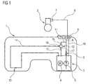
- FIG. 1 1 schematically shows a fuel tank 1 of a motor vehicle with a delivery unit 2 arranged therein for conveying fuel to an internal combustion engine 3.
- the delivery unit 2 has a fuel pump 5 driven by an electric motor 4 and is connected via a supply line 6 to an injection rail 7 of the internal combustion engine 3.
- a check valve 8 and a pressure relief valve 9 are arranged in the flow line 6, .
- the check valve 8 prevents emptying of the supply line 6 with the internal combustion engine 3, while the pressure relief valve 9 opens above a designated pressure and excess fuel via a return line 10 to the conveyor unit 2 returns.
- the supply line 6 is connected via a first fuel line 11 to a device 12 for controlling a pressure in the supply line 6.
- a second fuel line 13 connects the device 12 to the delivery unit 2.
- a third, connected to the device 12 fuel line 14 leads to a suction jet pump 15, which promotes fuel to the delivery unit 2.
- An inflow port 16 of the device 12 is connected to the leading to the flow line 6 fuel line 11.
- the device 12 has an outflow port 17 for connecting the fuel line 13 guided into the delivery unit 2 and a third port 18 for connecting the fuel line 14 leading to the suction jet pump 15.
- FIG. 2 schematically shows a first embodiment of the device 12 from FIG. 1 in which in a connection 19 between the inflow port 16 and the outflow port 17, a check valve 20 and a pressure relief valve 21 are arranged one behind the other.
- the check valve 20 and the pressure relief valve 21 each have a valve seat 22, 23, wherein the valve seats 22, 23 facing each other and between the valve seats 22, 23 a valve body 24 is movably arranged.
- the valve body 24 is biased in the illustrated, pressureless state by a spring element 25 against the valve seat 23 of the pressure relief valve 21.
- the port 18 of leading to the ejector 15 fuel line 14 is made FIG. 1 arranged.
- the device 12 between the valve seats 22, 23 arranged webs 26 for guiding the valve body 24.
- the valve body 24 has a disc 36 made of rubber-elastic material and two support plates 37 made of metal.
- the supply line 6 is filled with fuel.
- the valve body 24 is pushed away from the valve seat 23 of the pressure limiting valve 21, and fuel can flow from the inflow port 16 to the outflow port 17.
- the pressure in the flow line 6 is limited and prevents when switched off the engine 3 at the in FIG. 1 shown injection rail 7 fuel leaks.
- a high volume flow is promoted at high pressure.
- the high pressure and the high flow rate cause the valve body 24 is pressed by the force of the spring element 25 against the valve seat 22 of the check valve 20 and the Outflow connection 17 closes.
- fuel via the third port 18 to the in FIG. 1 shown suction jet pump 15 flow.
- the pressure in the supply line 6 is then of the in FIG. 1 illustrated pressure relief valve 9 and the flow rate of the fuel pump 5 determined.
- FIG. 3 schematically shows a second embodiment of the device 12 from FIG. 1 in the unpressurized state, in which in a connection 27 between the inflow port 16 and the Ausströman gleich 17 a check valve 28 and a pressure relief valve 29 are arranged one behind the other, wherein the check valve 28 is disposed closer to the Einströman gleich 16 than the pressure relief valve 29.
- the check valve 28 and the Pressure relief valve 29 each have a biased by a spring element 30, 31 valve body 32, 33 and a valve seat 34, 35.
- This device 12 has different from the FIG. 2 no connection for leading to the ejector 15 fuel line 14. However, the control of the flow from the inflow port 16 to the Ausströman gleich 17 happens as to the device 12 after FIG. 2 described.
Landscapes
- Engineering & Computer Science (AREA)
- General Engineering & Computer Science (AREA)
- Mechanical Engineering (AREA)
- Chemical & Material Sciences (AREA)
- Combustion & Propulsion (AREA)
- Fuel-Injection Apparatus (AREA)
Claims (9)
- Dispositif permettant de commander une pression dans une conduite d'alimentation en carburant de véhicule automobile, comportant un raccordement d'arrivée (16) prévu pour être raccordé à la conduite d'alimentation (6) et un raccordement de départ (17) et une soupape placée dans une liaison entre le raccordement d'arrivée (16) et le raccordement de départ (17), une soupape de limitation de pression (21, 29), qui obture la liaison (19, 27) entre le raccordement d'arrivée (16) et le raccordement de départ (17), lorsque la pression est inférieure à une première pression donnée, et une soupape de fermeture (20, 28), qui obture la liaison (19, 27) entre le raccordement d'arrivée (16) et le raccordement de départ (17), lorsque la pression est supérieure à une deuxième pression donnée, la première pression étant inférieure à la deuxième pression, caractérisé par le fait que la soupape de limitation de pression (21, 29) réduit un écoulement à travers la liaison lorsque la pression est supérieure à la première pression et le raccordement de départ (17) est prévu pour refluer du carburant dans un réservoir à carburant.
- Dispositif selon la revendication 1, caractérisé par le fait que la soupape de fermeture (20, 28) et la soupape de limitation de pression (21, 29) constituent une unité constructive unique.
- Dispositif selon la revendication 1 ou 2, caractérisé par le fait que la soupape de fermeture (20, 28) et la soupape de limitation de pression (21, 29) sont placées l'une derrière l'autre dans la direction de l'écoulement de carburant entre le raccordement d'arrivée (16) et le raccordement de départ (17).
- Dispositif selon au moins l'une des revendications précédentes, caractérisé par le fait que le raccordement d'arrivée (16) et le raccordement de départ (17) ont chacun un siège de soupape (22, 23) et qu'un corps de soupape séparé (24), qui est mobile entre les deux sièges de soupape (22, 23), est soumis à une force de précontrainte contre le siège de soupape (22) du raccordement d'arrivée (16) .
- Dispositif selon au moins l'une des revendications précédentes, caractérisé par le fait que la soupape de limitation de pression (29) et la soupape de fermeture (28) ont chacune un organe à ressort (30, 31) et un corps de soupape (32, 33) soumis à une force de précontrainte contre un siège de soupape (34, 35).
- Dispositif selon au moins l'une des revendications précédentes, caractérisé par le fait que la liaison (19) entre le siège (23) de la soupape de limitation de pression (21) et le siège (22) de la soupape de fermeture (20) a un branchement (18) pour un autre consommateur de carburant.
- Dispositif selon la revendication 4, caractérisé par le fait que le corps de soupape séparé (24), qui est mobile entre les deux sièges de soupape (22, 23), et une paroi guidant le corps de soupape (24) entre les sièges de soupape (22, 23) ont des sections transversales différentes.
- Dispositif selon l'une des revendications 4 ou 7, caractérisé par le fait que la liaison (19) entre les deux sièges de soupape (22, 23) comporte un canal destiné à faire dévier l'écoulement autour du corps de soupape séparé (24) entre la première pression et la deuxième pression.
- Dispositif selon l'une des revendications 4, 7 ou 8, caractérisé par le fait que le corps de soupape (24) comporte un disque plat (36) fabriqué en matière molle et des disques de soutien (37) qui y sont fixés.
Applications Claiming Priority (2)
| Application Number | Priority Date | Filing Date | Title |
|---|---|---|---|
| DE102004003113A DE102004003113A1 (de) | 2004-01-21 | 2004-01-21 | Vorrichtung zum Steuern eines Druckes in einer Kraftstoff-Vorlaufleitung |
| DE102004003113 | 2004-01-21 |
Publications (2)
| Publication Number | Publication Date |
|---|---|
| EP1557554A1 EP1557554A1 (fr) | 2005-07-27 |
| EP1557554B1 true EP1557554B1 (fr) | 2008-10-15 |
Family
ID=34625740
Family Applications (1)
| Application Number | Title | Priority Date | Filing Date |
|---|---|---|---|
| EP04106719A Expired - Lifetime EP1557554B1 (fr) | 2004-01-21 | 2004-12-20 | Dispositif de contrôle de la pression dans une ligne d'alimentation en carburant |
Country Status (4)
| Country | Link |
|---|---|
| US (1) | US7178511B2 (fr) |
| EP (1) | EP1557554B1 (fr) |
| DE (2) | DE102004003113A1 (fr) |
| ES (1) | ES2315618T3 (fr) |
Families Citing this family (3)
| Publication number | Priority date | Publication date | Assignee | Title |
|---|---|---|---|---|
| DE102004049286A1 (de) * | 2004-10-09 | 2006-04-20 | Robert Bosch Gmbh | Vorrichtung zum Fördern von Kraftstoff |
| WO2020236640A1 (fr) * | 2019-05-17 | 2020-11-26 | Dayco Ip Holdings, Llc | Soupape de protecteur de réservoir de carburant et systèmes de moteur la comprenant |
| MX2024001666A (es) * | 2021-08-06 | 2024-02-27 | Valmont Industries | Sistema, metodo y aparato para proporcionar una tapa de expansion de la caja de engranajes y un conjunto de valvula. |
Family Cites Families (18)
| Publication number | Priority date | Publication date | Assignee | Title |
|---|---|---|---|---|
| US3604446A (en) * | 1969-05-26 | 1971-09-14 | Garrett Corp | Valve |
| DE3701572A1 (de) * | 1987-01-21 | 1988-08-04 | Danfoss As | Druckbegrenzungsventil |
| US5050636A (en) * | 1990-10-17 | 1991-09-24 | Kawasaki Jukogyo Kabushiki Kaisha | Relief valve |
| JPH0749066A (ja) * | 1993-08-05 | 1995-02-21 | Nippondenso Co Ltd | 内燃機関の燃料蒸気蒸散防止装置 |
| US5477829A (en) * | 1994-08-08 | 1995-12-26 | Ford Motor Company | Automotive returnless fuel system pressure valve |
| GB9416784D0 (en) * | 1994-08-19 | 1994-10-12 | Lucas Ind Plc | Pressure regulation valve |
| JP3116746B2 (ja) * | 1994-10-04 | 2000-12-11 | トヨタ自動車株式会社 | 内燃機関の燃料供給装置 |
| US5713389A (en) * | 1995-08-24 | 1998-02-03 | Fmc Corporation | Check valve and check valve seat |
| DE19618707C2 (de) | 1996-05-09 | 1998-12-17 | Siemens Ag | Verfahren und Vorrichtung zur Regelung eines Kraftstoffvolumenstromes |
| DE19625565C2 (de) * | 1996-06-26 | 1998-07-23 | Bosch Gmbh Robert | Kraftstoff-Förderpumpe für eine Kraftstoff-Einspritzpumpe für Brennkraftmaschinen |
| DE19634899A1 (de) * | 1996-08-29 | 1998-03-05 | Bosch Gmbh Robert | Druckregelventil |
| US5715798A (en) * | 1997-02-24 | 1998-02-10 | Ford Global Technologies, Inc. | Fuel pump manifold |
| DE19725474B4 (de) * | 1997-06-17 | 2007-11-22 | Robert Bosch Gmbh | Mengenregelventil für ein Kraftstoffeinspritzsystem |
| JPH11280930A (ja) * | 1998-03-30 | 1999-10-15 | Denso Corp | ガス抜き弁 |
| DE19832842C1 (de) * | 1998-07-21 | 2000-02-17 | Bosch Gmbh Robert | Kraftstoff-Fördersystem zur Kraftstoffversorgung einer Brennkraftmaschine |
| DE19936287C2 (de) * | 1999-08-02 | 2003-04-30 | Bosch Gmbh Robert | Bedarfssteuerung für ein Kraftstoffördermodul mit variablem Systemdruck |
| DE10106095A1 (de) * | 2001-02-08 | 2002-08-29 | Bosch Gmbh Robert | Kraftstoffsystem, Verfahren zum Betreiben des Kraftstoffsystems, Computerprogramm sowie Steuer- und/oder Regelgerät zur Steuerung des Kraftstoffsystems |
| DE10209527A1 (de) * | 2002-03-04 | 2003-09-25 | Bosch Gmbh Robert | Einrichtung zur druckmodulierten Formung des Einspritzverlaufes |
-
2004
- 2004-01-21 DE DE102004003113A patent/DE102004003113A1/de not_active Withdrawn
- 2004-12-20 DE DE502004008259T patent/DE502004008259D1/de not_active Expired - Lifetime
- 2004-12-20 ES ES04106719T patent/ES2315618T3/es not_active Expired - Lifetime
- 2004-12-20 EP EP04106719A patent/EP1557554B1/fr not_active Expired - Lifetime
-
2005
- 2005-01-20 US US11/040,677 patent/US7178511B2/en not_active Expired - Fee Related
Also Published As
| Publication number | Publication date |
|---|---|
| US7178511B2 (en) | 2007-02-20 |
| DE502004008259D1 (de) | 2008-11-27 |
| DE102004003113A1 (de) | 2005-08-11 |
| ES2315618T3 (es) | 2009-04-01 |
| EP1557554A1 (fr) | 2005-07-27 |
| US20050155586A1 (en) | 2005-07-21 |
Similar Documents
| Publication | Publication Date | Title |
|---|---|---|
| EP2029884B1 (fr) | Pompe a jet aspirant | |
| DE112008002451B4 (de) | System und Methode zum Dosieren von Treibstoff in einem Hochdruck-Pumpensystem | |
| DE60215591T2 (de) | Kraftsoffeinspritzventil | |
| EP1776523B1 (fr) | Systeme d'injection de carburant | |
| EP1566536A1 (fr) | Système d'alimentation en carburant et procédé de contrôle de l'alimentation en carburant | |
| DE19651671C2 (de) | Steuerung einer Einspritzanlage für eine mehrzylindrige Brennkraftmaschine | |
| EP0988164B1 (fr) | Appareil de chauffage | |
| EP2031237B1 (fr) | Injecteur destiné à l'injection de carburant | |
| EP1557554B1 (fr) | Dispositif de contrôle de la pression dans une ligne d'alimentation en carburant | |
| EP0819844B1 (fr) | Distributeur à 3 voies pour un dispositif d'alimentation en carburant d'un moteur à combustion interne à injection | |
| EP1664522A1 (fr) | Module de filtration et soupape pour systeme d'alimentation en carburant | |
| EP1706287B1 (fr) | Unite d'acheminement de carburant | |
| EP1126160B1 (fr) | Injecteur pour injecter du carburant dans un moteur à combustion interne | |
| EP2468560B1 (fr) | Système de carburant | |
| DE102008036819B4 (de) | Überdrucksicherungsanordnung und Einspritzanlage für eine Brennkraftmaschine | |
| DE102009014072B4 (de) | Common-Rail-Einspritzsystem sowie Verfahren zur Druckentlastung eines Common-Rail-Einspritzsystems | |
| DE112011105285B4 (de) | Druckregler | |
| DE10114252C2 (de) | Verfahren zum Einspritzen von Kraftstoff in die Brennräume einer Brennkraftmaschine, sowie Kraftstoffeinspritzsystem für eine solche | |
| DE102007059851A1 (de) | Kraftstoffeinspritzeinrichtung für eine Brennkraftmaschine | |
| DE102012203724A1 (de) | Kraftstofffördereinrichtung für ein Kraftstoffeinspritzsystem mit einem Überströmventil sowie Überströmventil | |
| DE19738502A1 (de) | System zur Hochdruckerzeugung | |
| DE19933569B4 (de) | Einspritzsystem für eine Brennkraftmaschine | |
| EP1342912B1 (fr) | Système d'alimentation en carburant pour un moteur à combustion interne | |
| DE102018123878A1 (de) | Einspritzdüse | |
| DE19933567C1 (de) | Einspritzsystem für eine Brennkraftmaschine |
Legal Events
| Date | Code | Title | Description |
|---|---|---|---|
| PUAI | Public reference made under article 153(3) epc to a published international application that has entered the european phase |
Free format text: ORIGINAL CODE: 0009012 |
|
| AK | Designated contracting states |
Kind code of ref document: A1 Designated state(s): AT BE BG CH CY CZ DE DK EE ES FI FR GB GR HU IE IS IT LI LT LU MC NL PL PT RO SE SI SK TR |
|
| AX | Request for extension of the european patent |
Extension state: AL BA HR LV MK YU |
|
| 17P | Request for examination filed |
Effective date: 20050606 |
|
| AKX | Designation fees paid |
Designated state(s): DE ES FR GB IT |
|
| 17Q | First examination report despatched |
Effective date: 20070827 |
|
| GRAP | Despatch of communication of intention to grant a patent |
Free format text: ORIGINAL CODE: EPIDOSNIGR1 |
|
| RAP1 | Party data changed (applicant data changed or rights of an application transferred) |
Owner name: CONTINENTAL AUTOMOTIVE GMBH |
|
| GRAS | Grant fee paid |
Free format text: ORIGINAL CODE: EPIDOSNIGR3 |
|
| GRAA | (expected) grant |
Free format text: ORIGINAL CODE: 0009210 |
|
| AK | Designated contracting states |
Kind code of ref document: B1 Designated state(s): DE ES FR GB IT |
|
| REG | Reference to a national code |
Ref country code: GB Ref legal event code: FG4D Free format text: NOT ENGLISH |
|
| REF | Corresponds to: |
Ref document number: 502004008259 Country of ref document: DE Date of ref document: 20081127 Kind code of ref document: P |
|
| REG | Reference to a national code |
Ref country code: ES Ref legal event code: FG2A Ref document number: 2315618 Country of ref document: ES Kind code of ref document: T3 |
|
| PLBE | No opposition filed within time limit |
Free format text: ORIGINAL CODE: 0009261 |
|
| STAA | Information on the status of an ep patent application or granted ep patent |
Free format text: STATUS: NO OPPOSITION FILED WITHIN TIME LIMIT |
|
| 26N | No opposition filed |
Effective date: 20090716 |
|
| PGFP | Annual fee paid to national office [announced via postgrant information from national office to epo] |
Ref country code: DE Payment date: 20141231 Year of fee payment: 11 Ref country code: GB Payment date: 20141219 Year of fee payment: 11 Ref country code: ES Payment date: 20141226 Year of fee payment: 11 |
|
| PGFP | Annual fee paid to national office [announced via postgrant information from national office to epo] |
Ref country code: FR Payment date: 20141219 Year of fee payment: 11 |
|
| PGFP | Annual fee paid to national office [announced via postgrant information from national office to epo] |
Ref country code: IT Payment date: 20141218 Year of fee payment: 11 |
|
| REG | Reference to a national code |
Ref country code: DE Ref legal event code: R119 Ref document number: 502004008259 Country of ref document: DE |
|
| GBPC | Gb: european patent ceased through non-payment of renewal fee |
Effective date: 20151220 |
|
| REG | Reference to a national code |
Ref country code: FR Ref legal event code: ST Effective date: 20160831 |
|
| PG25 | Lapsed in a contracting state [announced via postgrant information from national office to epo] |
Ref country code: DE Free format text: LAPSE BECAUSE OF NON-PAYMENT OF DUE FEES Effective date: 20160701 Ref country code: GB Free format text: LAPSE BECAUSE OF NON-PAYMENT OF DUE FEES Effective date: 20151220 |
|
| PG25 | Lapsed in a contracting state [announced via postgrant information from national office to epo] |
Ref country code: FR Free format text: LAPSE BECAUSE OF NON-PAYMENT OF DUE FEES Effective date: 20151231 |
|
| PG25 | Lapsed in a contracting state [announced via postgrant information from national office to epo] |
Ref country code: IT Free format text: LAPSE BECAUSE OF NON-PAYMENT OF DUE FEES Effective date: 20151220 |
|
| REG | Reference to a national code |
Ref country code: ES Ref legal event code: FD2A Effective date: 20170127 |
|
| PG25 | Lapsed in a contracting state [announced via postgrant information from national office to epo] |
Ref country code: ES Free format text: LAPSE BECAUSE OF NON-PAYMENT OF DUE FEES Effective date: 20151221 |