EP1557559A1 - Soupape de carburant a haut debit et pompe d'alimentation en carburant equipee de ladite soupape - Google Patents
Soupape de carburant a haut debit et pompe d'alimentation en carburant equipee de ladite soupape Download PDFInfo
- Publication number
- EP1557559A1 EP1557559A1 EP03758922A EP03758922A EP1557559A1 EP 1557559 A1 EP1557559 A1 EP 1557559A1 EP 03758922 A EP03758922 A EP 03758922A EP 03758922 A EP03758922 A EP 03758922A EP 1557559 A1 EP1557559 A1 EP 1557559A1
- Authority
- EP
- European Patent Office
- Prior art keywords
- fuel
- valve
- inlet
- main body
- supply pump
- Prior art date
- Legal status (The legal status is an assumption and is not a legal conclusion. Google has not performed a legal analysis and makes no representation as to the accuracy of the status listed.)
- Withdrawn
Links
Images


Classifications
-
- F—MECHANICAL ENGINEERING; LIGHTING; HEATING; WEAPONS; BLASTING
- F02—COMBUSTION ENGINES; HOT-GAS OR COMBUSTION-PRODUCT ENGINE PLANTS
- F02M—SUPPLYING COMBUSTION ENGINES IN GENERAL WITH COMBUSTIBLE MIXTURES OR CONSTITUENTS THEREOF
- F02M59/00—Pumps specially adapted for fuel-injection and not provided for in groups F02M39/00 -F02M57/00, e.g. rotary cylinder-block type of pumps
- F02M59/44—Details, components parts, or accessories not provided for in, or of interest apart from, the apparatus of groups F02M59/02 - F02M59/42; Pumps having transducers, e.g. to measure displacement of pump rack or piston
- F02M59/46—Valves
- F02M59/464—Inlet valves of the check valve type
-
- F—MECHANICAL ENGINEERING; LIGHTING; HEATING; WEAPONS; BLASTING
- F02—COMBUSTION ENGINES; HOT-GAS OR COMBUSTION-PRODUCT ENGINE PLANTS
- F02M—SUPPLYING COMBUSTION ENGINES IN GENERAL WITH COMBUSTIBLE MIXTURES OR CONSTITUENTS THEREOF
- F02M45/00—Fuel-injection apparatus characterised by having a cyclic delivery of specific time/pressure or time/quantity relationship
- F02M45/02—Fuel-injection apparatus characterised by having a cyclic delivery of specific time/pressure or time/quantity relationship with each cyclic delivery being separated into two or more parts
- F02M45/04—Fuel-injection apparatus characterised by having a cyclic delivery of specific time/pressure or time/quantity relationship with each cyclic delivery being separated into two or more parts with a small initial part, e.g. initial part for partial load and initial and main part for full load
-
- F—MECHANICAL ENGINEERING; LIGHTING; HEATING; WEAPONS; BLASTING
- F02—COMBUSTION ENGINES; HOT-GAS OR COMBUSTION-PRODUCT ENGINE PLANTS
- F02M—SUPPLYING COMBUSTION ENGINES IN GENERAL WITH COMBUSTIBLE MIXTURES OR CONSTITUENTS THEREOF
- F02M47/00—Fuel-injection apparatus operated cyclically with fuel-injection valves actuated by fluid pressure
- F02M47/02—Fuel-injection apparatus operated cyclically with fuel-injection valves actuated by fluid pressure of accumulator-injector type, i.e. having fuel pressure of accumulator tending to open, and fuel pressure in other chamber tending to close, injection valves and having means for periodically releasing that closing pressure
- F02M47/027—Electrically actuated valves draining the chamber to release the closing pressure
-
- F—MECHANICAL ENGINEERING; LIGHTING; HEATING; WEAPONS; BLASTING
- F02—COMBUSTION ENGINES; HOT-GAS OR COMBUSTION-PRODUCT ENGINE PLANTS
- F02M—SUPPLYING COMBUSTION ENGINES IN GENERAL WITH COMBUSTIBLE MIXTURES OR CONSTITUENTS THEREOF
- F02M57/00—Fuel-injectors combined or associated with other devices
- F02M57/02—Injectors structurally combined with fuel-injection pumps
- F02M57/022—Injectors structurally combined with fuel-injection pumps characterised by the pump drive
- F02M57/025—Injectors structurally combined with fuel-injection pumps characterised by the pump drive hydraulic, e.g. with pressure amplification
-
- F—MECHANICAL ENGINEERING; LIGHTING; HEATING; WEAPONS; BLASTING
- F02—COMBUSTION ENGINES; HOT-GAS OR COMBUSTION-PRODUCT ENGINE PLANTS
- F02M—SUPPLYING COMBUSTION ENGINES IN GENERAL WITH COMBUSTIBLE MIXTURES OR CONSTITUENTS THEREOF
- F02M59/00—Pumps specially adapted for fuel-injection and not provided for in groups F02M39/00 -F02M57/00, e.g. rotary cylinder-block type of pumps
- F02M59/02—Pumps specially adapted for fuel-injection and not provided for in groups F02M39/00 -F02M57/00, e.g. rotary cylinder-block type of pumps of reciprocating-piston or reciprocating-cylinder type
- F02M59/10—Pumps specially adapted for fuel-injection and not provided for in groups F02M39/00 -F02M57/00, e.g. rotary cylinder-block type of pumps of reciprocating-piston or reciprocating-cylinder type characterised by the piston-drive
- F02M59/102—Mechanical drive, e.g. tappets or cams
-
- F—MECHANICAL ENGINEERING; LIGHTING; HEATING; WEAPONS; BLASTING
- F02—COMBUSTION ENGINES; HOT-GAS OR COMBUSTION-PRODUCT ENGINE PLANTS
- F02M—SUPPLYING COMBUSTION ENGINES IN GENERAL WITH COMBUSTIBLE MIXTURES OR CONSTITUENTS THEREOF
- F02M59/00—Pumps specially adapted for fuel-injection and not provided for in groups F02M39/00 -F02M57/00, e.g. rotary cylinder-block type of pumps
- F02M59/02—Pumps specially adapted for fuel-injection and not provided for in groups F02M39/00 -F02M57/00, e.g. rotary cylinder-block type of pumps of reciprocating-piston or reciprocating-cylinder type
- F02M59/10—Pumps specially adapted for fuel-injection and not provided for in groups F02M39/00 -F02M57/00, e.g. rotary cylinder-block type of pumps of reciprocating-piston or reciprocating-cylinder type characterised by the piston-drive
- F02M59/105—Pumps specially adapted for fuel-injection and not provided for in groups F02M39/00 -F02M57/00, e.g. rotary cylinder-block type of pumps of reciprocating-piston or reciprocating-cylinder type characterised by the piston-drive hydraulic drive
-
- F—MECHANICAL ENGINEERING; LIGHTING; HEATING; WEAPONS; BLASTING
- F02—COMBUSTION ENGINES; HOT-GAS OR COMBUSTION-PRODUCT ENGINE PLANTS
- F02M—SUPPLYING COMBUSTION ENGINES IN GENERAL WITH COMBUSTIBLE MIXTURES OR CONSTITUENTS THEREOF
- F02M63/00—Other fuel-injection apparatus having pertinent characteristics not provided for in groups F02M39/00 - F02M57/00 or F02M67/00; Details, component parts, or accessories of fuel-injection apparatus, not provided for in, or of interest apart from, the apparatus of groups F02M39/00 - F02M61/00 or F02M67/00; Combination of fuel pump with other devices, e.g. lubricating oil pump
- F02M63/0001—Fuel-injection apparatus with specially arranged lubricating system, e.g. by fuel oil
-
- F—MECHANICAL ENGINEERING; LIGHTING; HEATING; WEAPONS; BLASTING
- F02—COMBUSTION ENGINES; HOT-GAS OR COMBUSTION-PRODUCT ENGINE PLANTS
- F02M—SUPPLYING COMBUSTION ENGINES IN GENERAL WITH COMBUSTIBLE MIXTURES OR CONSTITUENTS THEREOF
- F02M2200/00—Details of fuel-injection apparatus, not otherwise provided for
- F02M2200/04—Fuel-injection apparatus having means for avoiding effect of cavitation, e.g. erosion
-
- F—MECHANICAL ENGINEERING; LIGHTING; HEATING; WEAPONS; BLASTING
- F02—COMBUSTION ENGINES; HOT-GAS OR COMBUSTION-PRODUCT ENGINE PLANTS
- F02M—SUPPLYING COMBUSTION ENGINES IN GENERAL WITH COMBUSTIBLE MIXTURES OR CONSTITUENTS THEREOF
- F02M2200/00—Details of fuel-injection apparatus, not otherwise provided for
- F02M2200/40—Fuel-injection apparatus with fuel accumulators, e.g. a fuel injector having an integrated fuel accumulator
-
- F—MECHANICAL ENGINEERING; LIGHTING; HEATING; WEAPONS; BLASTING
- F02—COMBUSTION ENGINES; HOT-GAS OR COMBUSTION-PRODUCT ENGINE PLANTS
- F02M—SUPPLYING COMBUSTION ENGINES IN GENERAL WITH COMBUSTIBLE MIXTURES OR CONSTITUENTS THEREOF
- F02M45/00—Fuel-injection apparatus characterised by having a cyclic delivery of specific time/pressure or time/quantity relationship
-
- F—MECHANICAL ENGINEERING; LIGHTING; HEATING; WEAPONS; BLASTING
- F02—COMBUSTION ENGINES; HOT-GAS OR COMBUSTION-PRODUCT ENGINE PLANTS
- F02M—SUPPLYING COMBUSTION ENGINES IN GENERAL WITH COMBUSTIBLE MIXTURES OR CONSTITUENTS THEREOF
- F02M61/00—Fuel-injectors not provided for in groups F02M39/00 - F02M57/00 or F02M67/00
- F02M61/16—Details not provided for in, or of interest apart from, the apparatus of groups F02M61/02 - F02M61/14
- F02M61/20—Closing valves mechanically, e.g. arrangements of springs or weights or permanent magnets; Damping of valve lift
- F02M61/205—Means specially adapted for varying the spring tension or assisting the spring force to close the injection-valve, e.g. with damping of valve lift
-
- F—MECHANICAL ENGINEERING; LIGHTING; HEATING; WEAPONS; BLASTING
- F02—COMBUSTION ENGINES; HOT-GAS OR COMBUSTION-PRODUCT ENGINE PLANTS
- F02M—SUPPLYING COMBUSTION ENGINES IN GENERAL WITH COMBUSTIBLE MIXTURES OR CONSTITUENTS THEREOF
- F02M63/00—Other fuel-injection apparatus having pertinent characteristics not provided for in groups F02M39/00 - F02M57/00 or F02M67/00; Details, component parts, or accessories of fuel-injection apparatus, not provided for in, or of interest apart from, the apparatus of groups F02M39/00 - F02M61/00 or F02M67/00; Combination of fuel pump with other devices, e.g. lubricating oil pump
- F02M63/02—Fuel-injection apparatus having several injectors fed by a common pumping element, or having several pumping elements feeding a common injector; Fuel-injection apparatus having provisions for cutting-out pumps, pumping elements, or injectors; Fuel-injection apparatus having provisions for variably interconnecting pumping elements and injectors alternatively
- F02M63/0225—Fuel-injection apparatus having a common rail feeding several injectors ; Means for varying pressure in common rails; Pumps feeding common rails
Definitions
- the present invention relates to a high flow rate fuel valve and a fuel supply pump with the valve.
- the present invention relates to a high flow rate fuel valve suitable for a fuel supply pump used in an accumulator fuel injection device (APCRS: Amplified Piston Common Rail System) that amplifies the pressure of a large flow rate of fuel through the use of a pressure piston, and a fuel supply pump with the valve.
- APCRS Amplified Piston Common Rail System
- JP 06-93936 A has proposed an accumulator fuel injection device having a first pressure accumulator 236 responsible for a main injection and a second pressure accumulator 278 responsible for a pilot injection. These pressure accumulators 236, 278 are switched by a switching device 286 to carry out a fuel injection.
- JP 2885076 B has proposed an accumulator fuel injection device having a pressure-amplifying piston for amplifying the pressure of a fuel and a cylinder chamber, located between a pressure accumulator and a fuel injection valve. More specifically, as shown in Fig.
- an accumulator fuel injection device 380 that comprises a pressure accumulator 395; an oil supply channel 360 for a fuel; an oil control channel 361; a switching valve 362 for fuel injection control; a pressure amplifying piston 378 for elevating the fuel pressure to 70 to 120 MPa (approximately 700 to 1,200 kgf/cm 2 ); a cylinder chamber 383 for housing the pressure amplifying piston 378; a hydraulic circuit 363; a piston-work switching valve (three-way solid valve for amplifier) 364; and a controller (not shown).
- JP 06-101597 A as shown in Fig. 22, there is proposed a fuel injection valve having a fuel spiral member and the angle formed between a fuel spiral flow channel and a circular flow channel is restricted. More specifically, the fuel provided with a revolving force by the fuel spiral member on the upstream side of a valve sheet flows between the tip portion of a valve body and the valve sheet toward a fuel injection hole and the spiral movement of the fuel flow forms a hollow portion in a flow channel between the tip of the valve body and the fuel injection hole.
- JP 10-47208 A as shown in Fig. 23, there is proposed a fuel injection valve that performs fuel injection by setting revolving energy to the flow of fuel. More specifically, there is disclosed a fuel injection valve where the numbers of periphery portions, flow channel portions, and revolving grooves are defined as 4 to 8, respectively. Each of the revolving grooves is eccentric with a predetermined distance from a valve axis. In addition, the side of the revolving groove far from the valve axis is tangentially connected to the periphery of a circular groove. The side surfaces of the respective grooves facing to the revolving groove are arranged in parallel with each other.
- the accumulator fuel injection device disclosed in JP 06-93936 A needs to be provided with two kinds of the pressure accumulator, their switching device, and so on. Therefore, there is a problem in that the accumulator fuel injection device is complicated and grown in size. In the accumulator fuel injection device, furthermore, there is an another problem in that a large amount of fuel cannot be pressurized sufficiently because the fuel is difficult to flow quickly to the fuel injection valve when the cam and plunger of the fuel supply pump are driven at high speed. As the flow rate of fuel is restricted, a large amount of fuel cannot be pressurized sufficiently.
- a pressure amplifying piston is placed between the pressure accumulator and the fuel injection valve to intend to provide a multi-stage pressure injection.
- a pressure pump for supplying the high-pressure fuel to the pressure accumulator.
- a pressure pump is one of the conventional pressure pumps used for the conventional accumulator fuel injection devices. Any fuel injection valve adapted for the pressure pump, which intends to supply a large amount of high-pressure fuel, is not designed.
- JP 06-101597 A and JP 10-47208 A are difficult to be used as high flow fuel valves because their structures differ fundamentally from the high flow fuel valves in that the proportion of the length of an injection hole to the diameter of the injection hole is restricted within a predetermined range, a revolving body is installed, and so on.
- the present inventors have found out that, by providing a plurality of inlet holes and arranging the inlet holes in a non-radical pattern relative to an inlet chamber, fuel can be allowed to pass through the inlet holes quickly in a quantitative manner to pressurize a large amount of fuel sufficiently even in the case of driving a cum and a plunger at high speed.
- an object of the present invention is to provide a fuel supply pump and a high flow value suitable for the fuel supply pump, wherein the fuel supply pump allows fuel to quickly pass through a pressure chamber of a high pressure pump to pressurize the fuel sufficiently when the cam and plunger in a fuel supply pump are driven at high speed to discharge a large amount of the fuel.
- a first embodiment of the present invention is a high flow fuel valve 73 that comprises a valve main body 19, a valve body 20 movably installed in the inside of the valve main body 19, an inlet chamber 19a formed in the inside of the valve main body 19, inlet holes 19c, and a seat portion 23 where part of the valve body 20 and part of the valve main body 19 are contact with each other.
- the high flow fuel valve 73 is characterized in that a plurality of inlet holes 19c is formed and these inlet holes 19c are arranged in a non-radical pattern relative to the inlet chamber 19a.
- valve main body is not specifically limited to a certain configuration as far as it retains a valve body and performs a predetermined movement.
- the valve main body may be in the shape of a cap opened downwardly as shown in Fig. 1(b).
- the external shape of the valve main body 19 is substantially in the form of a cylinder, while no protrusion, rib, or the like is formed thereon so as to be substantially flat.
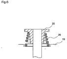
- a rib portion 33 is formed on the upper portion of the valve main body 19 as shown in Fig. 8(b) and then the rib portion 33 is used for fixing the valve main body in position with respect to a barrel or the like. Therefore, there are problems in that the valve main body is hardly produced and the cost thereof increases. Therefore, as shown in Fig. 2, The problems in producing the valve main body can be solved by carrying out the centering by adjusting the inner diameter of a valve retaining portion 71 and the external diameter of a valve 73, while no rib portion or the like is formed on the valve main body.
- valve body is installed in the valve main body.
- the valve body is movable in the inside of the valve main body. That is, it is preferable to constitute a poppet valve structure.
- a method for driving the valve body installed in the valve main body is, but not specifically limited to, preferably a mechanical driving method using a valve spring 21 provided above the valve main body 19.
- an electro-magnetic driving method may be preferably applied.
- the valve body has a sheet diameter of 8 mm or more. This is because such a configuration of the valve body leads to secure fuel at a flow rate of approximately 500 to 1,500 litters per hour and to supply the fuel to a fuel supply pump to pressurize a large amount of fuel. In addition, this is also because an ultra-high pressure injection of 180 MPa or more can be easily attained even if the fuel supply pump is coupled with an accumulator fuel injection device used together with a pressure amplifying piston.
- the high flow fuel valve itself grows in size as the sheet diameter of the valve body increases too much. Therefore, it may lead to be difficult in installation of the high flow valve and high-precision movement of the valve body, or decrease in durability or mechanical strength of the valve body.
- the sheet diameter of the valve body is preferably in the range of 8 to 15 mm, more preferably in the range of 8 to 12 mm.
- the area (opening area) of one inlet hole is preferably in the range of 15 to 250 mm 2 .
- the area of the inlet hole exceeds 250 mm 2 , the mechanical strength or durability of the inlet hole may decrease.
- the area of the inlet hole is more preferably in the range of 20 to 200 mm 2 , further preferably in the range of 25 to 150 mm 2 .
- the term "area of one inlet hole” means the area of one opening portion 19b opened toward the inlet chamber 19a.
- the first embodiment is characterized in that part of a valve body 20 and part of a valve main body 19 are contact with each other to provide a seat portion 23 as a fuel-passing portion for correctly controlling the mount of fuel passed.
- the valve body moves up and down by means of a valve spring or the like, so that the valve body and valve main body can be partially contact with each other to form such a seat portion. Therefore, the fuel, even in a large amount, can be allowed to pass quickly through the high flow fuel valve in a quantitative manner.
- the seat portion is more preferably constructed such that the fuel-passing area of the seat portion is smaller than the area of the inlet hole.
- valve spring for driving a valve body 20 above a valve main body 19.
- valve body can be moved up and down by the valve spring to allow the valve main body and valve body to be easily contact with each other, while absorbing a seat impact at the time of lifting the valve body.
- a second valve spring 24 is preferably installed together with the first valve spring (first spring) 21. That is, the second valve spring 24 is provided such that it is brought into contact with a valve body 20 from an initial stage of lifting the valve body 20. It is preferable to install the second valve spring 24 having a comparatively high spring constant together with the first spring 21 having a comparatively low spring constant from the middle stage of the lifting so as to be brought into contact with the valve body 20.
- the valve body can be easily lifted at initial valve opening, so that the fuel inlet efficiency to a plunger can be increased.
- an increasing lifting speed is lowered by the second valve spring to reduce impact force at full lift. Therefore, even in the case of the high flow fuel valve, reduction in durability and strength can be prevented and also impact noises at the time of seating the valve body can be reduced.
- the second valve spring may be alternatively a spring 24 as shown in Fig. 4 or a flat spring 25 as shown in Fig. 5(a) to Fig. 5(c).
- a non-linear spring 26 as shown in Fig. 6 is preferably used. That is, for example, the spring is constructed such that the spring has a conical shape gradually increasing in diameter toward the bottom. Therefore, the spring constant can be variable and the same effects as those obtained by installing the first and second valve springs can be obtained without increasing the number of the valve spring.
- the flow rate of fuel per unit time when the lift of a valve body is almost 1 mm is preferably in the range of 500 to 1,500 liters per hour, more preferably in the range of 800 to 1,300 liters per hour.
- the high flow fuel valve of the first embodiment has a performance curve shown in Fig. 7. That is, in Fig. 7, the lift (relative value) of the valve body is plotted on the abscissa and the flow rate of fuel per unit of time, i.e., flow velocity (relative value) is plotted on the ordinate.
- the line A corresponds to the conventional fuel valve.
- this is a fuel valve 32 having a sheet diameter of 7.6 mm, in which three inlet holes 19c are arranged in a radial pattern along the periphery of a circular inlet chamber 18 (Type 1).
- the line B corresponds to a modified example of the conventional valve having an enlarged sheet diameter.
- this is a fuel valve 34 having a sheet diameter of 10 mm, in which three inlet holes 19c are arranged in a radial pattern along the periphery of a circular inlet chamber 18 (Type 2).
- the line C corresponds to one example of the high flow fuel valve of the present invention.
- this is a high flow fuel valve 73 having a sheet diameter of 10 mm, in which three inlet holes 19c are arranged in a non-radial pattern along the tangent of a circular inlet chamber 18 (Type 3).
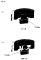
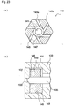
- Fig. 10(a) and Fig. 10(b) illustrate throttle positions of the conventional fuel valve shown in Fig. 8, respectively. These figures correspond to the valve of Type 1 described above.
- Fig. 11(a) and Fig. 11(b) illustrate throttle positions of the modified example of the conventional fuel valve shown in Fig. 9, respectively. These figures correspond to the valve of Type 2 described above.
- Fig. 12(a) and Fig. 12(b) illustrate throttle positions of the high flow fuel valve shown in Fig. 1, respectively. These figures correspond to the valve of Type 3 described above.
- valve of Type 3 it is confirmed that inlet holes are tangentially arranged and the sheet diameter is enlarged, so that the throttle position can be only found on the seat position irrespective of the lift of the valve and the throttle of the inlet chamber 18 is improved, even compared with the valve of Type 2.
- a second embodiment of the present invention is a fuel supply pump 50 having a fuel inlet valve 73 and a fuel outlet valve 19 and is characterized by the following configuration.
- the fuel inlet valve 73 comprises a valve main body 19, a valve body 20 movably installed in the inside of the valve main body 19, an inlet chamber 19a formed in the inside of the valve main body 19, inlet holes 19c, a seat portion 23 where part of the valve body 20 and part of the valve main body 19 are contact with each other, wherein a plurality of inlet holes 19c is formed and these inlet holes 19c are arranged in a non-radical pattern.
- the second embodiment is characterized in that a fuel inlet valve used is the high flow fuel valve described in the first embodiment.
- a fuel inlet valve used is the high flow fuel valve described in the first embodiment.
- the high flow fuel valve of the first embodiment when used as a fuel inlet valve, even if the flow of fuel per unit of time is approximately 500 to 1,500 liters per hour, the fuel can be quantitatively supplied to a fuel supply pump in a extremely precise manner.
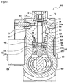
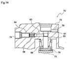
- the configuration of the fuel supply pump is, but not specifically limited to, preferably one having a fuel supply pump 50 shown in Fig. 13. That is, the fuel supply pump is preferably constructed of a pump housing 52, a barrel (cylinder) 53, a plunger 54, a fuel compression chamber 74, a tappet 58, and a cam 60.
- the plunger 54 slides along the inside of the barrel 53 in the pump housing 52 to form a fuel compression chamber 74 for pressurizing fuel.
- the plunger 54 is preferably constructed so as to perform reciprocal motion in response to the rotary movement of the cam 60. Therefore, the fuel fed under pressure from a feed pump 64 is effectively pressurized by the plunger 54 in the fuel compression chamber 74, resulting in high pressure fuel.
- two sets of the barrel (cylinder) 53 and the plunger 54 are installed in the pump housing 52.
- two or more sets are preferably used.
- the fuel supply pump of the second embodiment is preferably a part of an amplified piston common rail system using a mechanical pressure amplifying system such as piston.
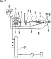
- the fuel supply pump 103 is preferably constructed of a fuel tank 102, a feed pump (low pressure pump) 104 for supplying the fuel from the fuel tank 102, a fuel supply pump (high pressure pump) 103, a common rail 106 provided as a pressure accumulator for pressure-accumulation of the fuel fed under pressure from the fuel supply pump 103, a piston amplifier 108, and a fuel injection system 110.
- the capacity and form of a fuel tank 102 exemplified in Fig. 15 are preferably defined in consideration of, for example, the circulation of fuel at a flow rate of approximately 500 to 1,500 liters per hour.
- the feed pump 104 is, as shown in Fig. 15, provided for feeding fuel (diesel oil) in the fuel tank 102 to the fuel supply pump 103 under pressure. It is preferable that a filter 105 is placed between the feed pump 104 and the fuel supply pump 103.
- the feed pump 104 has a gear pump structure mounted on the end of the cam such that the feed pump 104 can be driven by directly connecting with the axis of the cam or through an appropriate gear ratio.
- the fuel supply pump 103 is a device for pressurizing fuel supplied from the feed pump 104 at high pressure.
- the fuel supply pump 103 is constructed such that, after pressurizing the fuel, the fuel is fed to the common rail 106 under pressure through a high pressure channel 107.
- the fuel fed under pressure from the feed pump 104 through the filter 105 is preferably supplied to the fuel supply pump 103 through a proportional control valve (FMU) 120 for adjusting the amount of fuel injected as shown in Fig. 16.
- the proportional control valve 120 controls the amount of current passing through a coil 124 under the control of ECU to proportionally adjust the position of an anchor 125. That is, the position of a piston 127 at the tip portion of the anchor 125 is adjusted in response to the position of the anchor 125, so that the fuel-passing area between a slit 122 formed in the piston 127 and the fuel supply portion 129 can be varied to control the fuel supplied to an inlet valve (not shown) in the fuel supply pump 103.
- the fuel in addition to feed the fuel supplied from the feed pump 104 to the proportional control valve 120 and the fuel supply pump 103 under pressure, it is preferable to construct that the fuel is returned to the fuel tank 102 through a overflow valve (OFV) 134 installed in parallel with the proportional control valve 120. Moreover, it is preferable that part of the fuel is fed under pressure to a bearing (not shown) of the fuel supply pump 103 and then used as a fuel lubricating oil of the bearing.
- OFV overflow valve
- the fuel supplypump 103 is a device for pressurizing the fuel supplied from the feed pump 104 at high pressure as described above.
- the fuel supply pump 103 is preferably constructed such that, after pressurizing the fuel, the fuel is fed to the common rail 106 under pressure through the high pressure channel 107.
- a one way valve (not shown) on the outlet of the fuel supply pump 103, or both of the common rail 106 described below and the fuel supply pump 103.
- the common rail 106 is connected to a plurality of injectors (injection valves) 110.
- injectors injection valves
- the accumulated pressure fuel at high pressure by the common rail 106 is injected into an internal combustion engine (not shown) from each of the injectors 110.
- the amount of discharge from each of these injectors 110 is preferably controlled through an injector driving unit (IDU).
- the IDU is connected to an electrical controlling unit (ECU) provided as a controller described letter.
- the IDU is driven by drive signals from the ECU.
- a pressure detector 117 is connected to the side end of the common rail 106 and a pressure-detection signal obtained by the pressure detector 117 is preferably sent to the ECU. That is, it is preferable to control an electromagnetic control valve (not shown) and also control the drive of IDU in response to the pressure detected when the ECU receives the pressure-detection signal from the pressure detector 117.
- a piston amplifier pressure amplifying piston
- a piston amplifier is constructed of a cylinder 155, a mechanical piston 154, a compression chamber 158, an electromagnetic valve 170, and a circulation pathway 157.
- the mechanical piston 154 is equipped with a pressure-receiving portion 152 having a comparatively large area and a pressure portion 156 having a comparatively small area.
- the common rail pressure of the compression chamber 158 is preferably adjusted to one that allows fuel having a pressure of approximately 50 MPa to be pressurized by the pressure portion 156 having a comparatively small area to make the pressure of the fuel within the range of 150 to 300 MPa.
- a large amount of fuel having the common rail pressure is used for pressurizing the mechanical piston 154. After pressurization, it is preferable to flow the fuel back to the fuel tank or the like through an electromagnetic driven overflow valve 170. That is, a major part of the fuel having the common rail pressure is pressurized by the mechanical piston 154 and then flows back to the fuel tank or the like together with spilled fuel. Then, the fuel is preferably used for pressurizing the mechanical piston 154 again.
- the fuel pressurized by the pressure portion 156 is fed to a fuel injection system (fuel injection nozzle) 163, effectively injected, and combusted.
- a fuel injection system fuel injection nozzle
- the mechanical piston can be effectively pushed by the fuel having a common rail pressure without excessively increasing the size of the common rail.
- a mechanical piston is equipped with a pressure-receiving portion having a comparatively large area and a pressure portion having a comparatively small area. While considering the stroke of the mechanical piston, it is possible to effectively pressurize e fuel having the common rail pressure to a desired level with a small pressure.
- the fuel from the common rail (pressure: p1, volume: V1, work load: W1) can be received by a pressure-receiving portion having a comparatively large area and then changed to higher-pressure fuel (pressure: p2, volume: V2, work load: W2) by a mechanical piston equipped with a pressure portion having a comparatively small area.
- the configuration of the fuel injection system (fuel injection nozzle) 110 is, but not specifically limited to, preferably constructed as follows: As shown in Fig. 17, for example, the fuel injection system 110 comprises a seat surface 164 on which a needle valve body 162 can be placed on a seat surface 164, an injection hole 165 formed on the downstream side from the valve body abutting portion of the seat surface 164. Preferably, it is constructed that the fuel supplied from the upstream side of the seat surface 164 at the time of lifting a needle valve body 162 is introduced into the injection hole 165.
- such a fuel injection nozzle system 166 is preferably of an electromagnetic valve type, in which the needle valve body 162 is always energized toward the seat surface 164 by the spring 161 and opens and shuts the needle valve body 162 by switching energization / no energization of solenoide 180.
- a time chart of high-pressure fuel injection it is preferable to indicate a fuel injection chart having two-staged injection conditions as indicated by the solid line as exemplified in Fig. 19.
- a fuel injection chart as indicated by the dashed line B in Fig. 19, a combination of the common rail pressure and amplification with a piston amplifier.
- the conventional injection timing chart becomes a single-stage injection timing chart with a low injection amount as indicated by the dashed line C in Fig. 19.
- the fuel supply pump 103 the actions of the piston amplifier 108, and the fuel injection valve 110 in the second embodiment will be described. That is, as shown in Fig. 15, at the time of operating the fuel injection system (fuel injection nozzle system) 110, the fuel in the fuel tank 102 is supplied from the feed pump 104 to the fuel supply pump 103. Then, the high-pressure fuel is supplied from the fuel supply pump 103 to the high pressure channel 107 under pressure.
- the fuel is subjected to pressure accumulation at approximately 50 MPa in the common rail 106 and then the fuel is preferably pressurized under ultra-high pressure conditions of 180 MPa or more as the piston amplifier 108 is provided between the common rail 106 and the fuel injection valve 110.
- the high flow fuel valve in which a plurality of inlet holes are formed and arranged in a non-radial pattern relative to the inlet chamber, is used as a fuel inlet valve of the fuel supply pump 103. Therefore, for example, the fuel at a flow rate of approximately 500 to 1, 500 litters per hours can be passed quickly and quantitatively. In addition, a large amount of fuel can be processed by both the fuel supply pump 103 and the common rail 106.
- a plurality of inlet holes is formed and these inlet holes are arranged in a non-radical pattern relative to the inlet chamber. Therefore, for example, even the fuel at a flow rate of approximately 500 to 1,500 liter per hour can be passed quickly and quantitatively.
- the high flow fuel of the present invention even if the lift of the valve body is comparatively low, a large amount of fuel at a flow rate of 1,000 liters per hour or more can be passed. Therefore, the positional change of the valve body decreases and the impact at the time of seating can be eased now.
- the high flow fuel valve of the present invention a large amount of fuel can be allowed to pass through the inlet holes quickly in a quantitative manner without excessively enlarging the diameter or cross-sectional area of the inlet hole. Therefore, the reduction of durability or strength of the high flow fuel valve itself can be prevented.
- the high flow fuel valve of the present invention can be suitably used as a high flow fuel valve of the fuel supply pump used in an amplified piston common rail system (APCRS) that pressurizes a large amount of fuel using a piston.
- APCRS amplified piston common rail system
- the fuel supply pump provided with the high flow fuel valve of the present invention is equipped with the high flow valve having a plurality of inlet holes arranged in a non-radial pattern relative to the inlet chamber. Therefore, for example, even the fuel at a flow rate of approximately 500 to 1,500 liter per hour can be passed quickly and quantitatively.
Landscapes
- Engineering & Computer Science (AREA)
- Chemical & Material Sciences (AREA)
- Combustion & Propulsion (AREA)
- Mechanical Engineering (AREA)
- General Engineering & Computer Science (AREA)
- Physics & Mathematics (AREA)
- Fluid Mechanics (AREA)
- Fuel-Injection Apparatus (AREA)
Applications Claiming Priority (5)
| Application Number | Priority Date | Filing Date | Title |
|---|---|---|---|
| JP2002313763A JP2004150290A (ja) | 2002-10-29 | 2002-10-29 | 燃料供給用ポンプおよびタペット構造体 |
| JP2002313763 | 2002-10-29 | ||
| JP2002381008 | 2002-12-27 | ||
| JP2002381008A JP2004211580A (ja) | 2002-12-27 | 2002-12-27 | 大流量燃料用バルブおよびそれを備えた燃料供給用ポンプ |
| PCT/JP2003/013687 WO2004040122A1 (fr) | 2002-10-29 | 2003-10-27 | Soupape de carburant a haut debit et pompe d'alimentation en carburant equipee de ladite soupape |
Publications (2)
| Publication Number | Publication Date |
|---|---|
| EP1557559A1 true EP1557559A1 (fr) | 2005-07-27 |
| EP1557559A4 EP1557559A4 (fr) | 2006-06-07 |
Family
ID=32232636
Family Applications (1)
| Application Number | Title | Priority Date | Filing Date |
|---|---|---|---|
| EP03758922A Withdrawn EP1557559A4 (fr) | 2002-10-29 | 2003-10-27 | Soupape de carburant a haut debit et pompe d'alimentation en carburant equipee de ladite soupape |
Country Status (4)
| Country | Link |
|---|---|
| EP (1) | EP1557559A4 (fr) |
| KR (1) | KR100709867B1 (fr) |
| AU (1) | AU2003275676A1 (fr) |
| WO (1) | WO2004040122A1 (fr) |
Cited By (7)
| Publication number | Priority date | Publication date | Assignee | Title |
|---|---|---|---|---|
| EP1770274A1 (fr) * | 2005-09-29 | 2007-04-04 | Denso Corporation | Pompe à piston pour fluides et procédé de moulage monobloc du boîtier de ladite pompe |
| EP2058507A1 (fr) * | 2007-11-06 | 2009-05-13 | Robert Bosch GmbH | Injecteur de carburant doté d'un amortisseur de chocs optimisé |
| EP2184491A1 (fr) * | 2008-11-07 | 2010-05-12 | Delphi Technologies Holding S.à.r.l. | Tête de pompe pour ensemble de pompe à carburant |
| US8840083B2 (en) | 2008-09-23 | 2014-09-23 | Continental Automotive Gmbh | Intake valve for a cylinder of the high-pressure fuel pump of a common rail injection system |
| ITMI20130569A1 (it) * | 2013-04-10 | 2014-10-11 | Bosch Gmbh Robert | Gruppo di pompaggio per alimentare combustibile, preferibilmente gasolio, ad un motore a combustione interna |
| WO2014191220A1 (fr) * | 2013-05-29 | 2014-12-04 | Robert Bosch Gmbh | Pompe à haute pression pour système d'injection de carburant |
| US11591994B2 (en) | 2017-11-22 | 2023-02-28 | Hitachi Astemo, Ltd. | Fuel injection device |
Families Citing this family (2)
| Publication number | Priority date | Publication date | Assignee | Title |
|---|---|---|---|---|
| DE102004028073B3 (de) * | 2004-06-09 | 2005-08-04 | Siemens Ag | Rückschlagventil |
| ITMI20050719A1 (it) * | 2005-04-21 | 2006-10-22 | Dellorto Spa | Attuatore piezoelettrico per l'azionamento di una pompa d'iniezione per motori a combustione interna e complesso iniettore-pompa con esso realizzato |
Family Cites Families (9)
| Publication number | Priority date | Publication date | Assignee | Title |
|---|---|---|---|---|
| GB431140A (en) * | 1933-12-22 | 1935-06-24 | Simms Motor Units Ltd | Improvements relating to liquid fuel injection pumps |
| DE2261726C2 (de) * | 1972-12-16 | 1985-10-10 | Klöckner-Humboldt-Deutz AG, 5000 Köln | Kraftstoffeinspritzventil für Brennkraftmaschinen |
| DE2841986A1 (de) * | 1978-09-27 | 1980-04-10 | Daimler Benz Ag | Luftverdichtende einspritzbrennkraftmaschine mit direkteinspritzung und im kolben angeordnetem brennraum |
| JPS59140972A (ja) * | 1983-01-31 | 1984-08-13 | Yamatake Honeywell Co Ltd | ケ−ジ弁 |
| JP2518481Y2 (ja) * | 1988-02-22 | 1996-11-27 | 株式会社三ツ葉電機製作所 | 燃料圧力制御弁装置 |
| US5540564A (en) * | 1993-11-12 | 1996-07-30 | Stanadyne Automotive Corp. | Rotary distributor type fuel injection pump |
| GB2352780A (en) | 1999-03-23 | 2001-02-07 | Nachi Fujikoshi Corp | High pressure plunger pump |
| JP3525883B2 (ja) * | 1999-12-28 | 2004-05-10 | 株式会社デンソー | 燃料噴射ポンプ |
| DE10132246A1 (de) * | 2001-07-04 | 2003-01-23 | Bosch Gmbh Robert | Kraftstoffinjektor mit hochdruckfestem Zulauf |
-
2003
- 2003-10-27 AU AU2003275676A patent/AU2003275676A1/en not_active Abandoned
- 2003-10-27 WO PCT/JP2003/013687 patent/WO2004040122A1/fr not_active Ceased
- 2003-10-27 EP EP03758922A patent/EP1557559A4/fr not_active Withdrawn
- 2003-10-27 KR KR1020047017618A patent/KR100709867B1/ko not_active Expired - Fee Related
Cited By (15)
| Publication number | Priority date | Publication date | Assignee | Title |
|---|---|---|---|---|
| EP2246556A1 (fr) * | 2005-09-29 | 2010-11-03 | Denso Corporation | Pompe à piston pour fluides et procédé de moulage monobloc du boîtier de ladite pompe |
| US8075287B2 (en) | 2005-09-29 | 2011-12-13 | Denso Corporation | Fluid pump having plunger and method of monoblock casting for housing of the same |
| EP1770274A1 (fr) * | 2005-09-29 | 2007-04-04 | Denso Corporation | Pompe à piston pour fluides et procédé de moulage monobloc du boîtier de ladite pompe |
| EP2058507A1 (fr) * | 2007-11-06 | 2009-05-13 | Robert Bosch GmbH | Injecteur de carburant doté d'un amortisseur de chocs optimisé |
| DE102008048450B4 (de) * | 2008-09-23 | 2014-10-30 | Continental Automotive Gmbh | Saugventil für einen Zylinder der Kraftstoff-Hochdruckpumpe eines Common-Rail-Einspritzsystems |
| US8840083B2 (en) | 2008-09-23 | 2014-09-23 | Continental Automotive Gmbh | Intake valve for a cylinder of the high-pressure fuel pump of a common rail injection system |
| EP2184491A1 (fr) * | 2008-11-07 | 2010-05-12 | Delphi Technologies Holding S.à.r.l. | Tête de pompe pour ensemble de pompe à carburant |
| ITMI20130569A1 (it) * | 2013-04-10 | 2014-10-11 | Bosch Gmbh Robert | Gruppo di pompaggio per alimentare combustibile, preferibilmente gasolio, ad un motore a combustione interna |
| WO2014191220A1 (fr) * | 2013-05-29 | 2014-12-04 | Robert Bosch Gmbh | Pompe à haute pression pour système d'injection de carburant |
| CN105247200A (zh) * | 2013-05-29 | 2016-01-13 | 罗伯特·博世有限公司 | 用于燃料喷射系统的高压泵 |
| KR20160011634A (ko) * | 2013-05-29 | 2016-02-01 | 로베르트 보쉬 게엠베하 | 연료 분사 시스템용 고압 펌프 |
| US10100795B2 (en) | 2013-05-29 | 2018-10-16 | Robert Bosch Gmbh | High pressure pump for a fuel injection system |
| CN105247200B (zh) * | 2013-05-29 | 2019-06-11 | 罗伯特·博世有限公司 | 用于燃料喷射系统的高压泵 |
| KR102165469B1 (ko) | 2013-05-29 | 2020-10-14 | 로베르트 보쉬 게엠베하 | 연료 분사 시스템용 고압 펌프 |
| US11591994B2 (en) | 2017-11-22 | 2023-02-28 | Hitachi Astemo, Ltd. | Fuel injection device |
Also Published As
| Publication number | Publication date |
|---|---|
| AU2003275676A1 (en) | 2004-05-25 |
| EP1557559A4 (fr) | 2006-06-07 |
| KR100709867B1 (ko) | 2007-04-23 |
| WO2004040122A1 (fr) | 2004-05-13 |
| KR20050042080A (ko) | 2005-05-04 |
Similar Documents
| Publication | Publication Date | Title |
|---|---|---|
| EP1081372B1 (fr) | Dispositif d'injection de carburant | |
| CN1080825C (zh) | 内燃机用的喷油装置 | |
| USRE37241E1 (en) | Solenoid controlled variable pressure injector | |
| KR20070110446A (ko) | 연료공급용 펌프 및 태핏 구조체 | |
| EP1557559A1 (fr) | Soupape de carburant a haut debit et pompe d'alimentation en carburant equipee de ladite soupape | |
| JP2009133306A (ja) | 燃料噴射システム | |
| EP1780401B1 (fr) | Dispositif d'injection de carburant | |
| US20050106035A1 (en) | High flow rate fuel valve and fuel supply pump with the valve | |
| EP2703625A1 (fr) | Dispositif de mesure destiné à une pompe haute pression | |
| US7513756B2 (en) | Fuel supply pump and tappet structure body | |
| US20050100466A1 (en) | Fuel supply pump | |
| EP1557558B1 (fr) | Pompe d'alimentation en carburant et corps à structure poussoir | |
| US20090126695A1 (en) | Radial Piston Pump For Supplying Fuel At High Pressure To An Internal Combustion Engine | |
| JP2003314409A (ja) | 内燃機関用の燃料噴射装置 | |
| EP1582735A1 (fr) | Pompe d'alimentation en combustible | |
| US6935580B2 (en) | Valve assembly having multiple rate shaping capabilities and fuel injector using same | |
| JP4861958B2 (ja) | 高圧燃料ポンプ | |
| JP4120113B2 (ja) | 燃料噴射装置 | |
| EP0582993B1 (fr) | Dispositif d'injection de carburant avec accumulateur | |
| US20030010319A1 (en) | Fuel injection device | |
| MXPA00012603A (es) | Montaje inyector de combustible que tiene una inyeccion inicial combinada y un regulador de presion maxima de inyeccion. | |
| US6345804B1 (en) | Control valve for fuel injection devices for internal combustion engines | |
| EP1490595A1 (fr) | Systeme d'injection de carburant | |
| JP2004211580A (ja) | 大流量燃料用バルブおよびそれを備えた燃料供給用ポンプ | |
| JP4229059B2 (ja) | 内燃機関用燃料噴射装置 |
Legal Events
| Date | Code | Title | Description |
|---|---|---|---|
| PUAI | Public reference made under article 153(3) epc to a published international application that has entered the european phase |
Free format text: ORIGINAL CODE: 0009012 |
|
| 17P | Request for examination filed |
Effective date: 20050127 |
|
| AK | Designated contracting states |
Kind code of ref document: A1 Designated state(s): AT BE BG CH CY CZ DE DK EE ES FI FR GB GR HU IE IT LI LU MC NL PT RO SE SI SK TR |
|
| AX | Request for extension of the european patent |
Extension state: AL LT LV MK |
|
| RBV | Designated contracting states (corrected) |
Designated state(s): AT BE BG CH CY CZ DE DK EE ES FI FR GB GR HU IE IT LI LU MC NL PT RO SE SI SK TR |
|
| DAX | Request for extension of the european patent (deleted) | ||
| RBV | Designated contracting states (corrected) |
Designated state(s): DE FR GB |
|
| A4 | Supplementary search report drawn up and despatched |
Effective date: 20060424 |
|
| STAA | Information on the status of an ep patent application or granted ep patent |
Free format text: STATUS: THE APPLICATION IS DEEMED TO BE WITHDRAWN |
|
| 18D | Application deemed to be withdrawn |
Effective date: 20080503 |