EP1557728B1 - Dispositif de correction automatique - Google Patents
Dispositif de correction automatique Download PDFInfo
- Publication number
- EP1557728B1 EP1557728B1 EP04026351.9A EP04026351A EP1557728B1 EP 1557728 B1 EP1557728 B1 EP 1557728B1 EP 04026351 A EP04026351 A EP 04026351A EP 1557728 B1 EP1557728 B1 EP 1557728B1
- Authority
- EP
- European Patent Office
- Prior art keywords
- fact
- crown
- crown body
- coupling
- sleeve
- Prior art date
- Legal status (The legal status is an assumption and is not a legal conclusion. Google has not performed a legal analysis and makes no representation as to the accuracy of the status listed.)
- Expired - Lifetime
Links
- 230000008878 coupling Effects 0.000 claims description 19
- 238000010168 coupling process Methods 0.000 claims description 19
- 238000005859 coupling reaction Methods 0.000 claims description 19
- 230000005540 biological transmission Effects 0.000 claims description 2
- 230000006835 compression Effects 0.000 claims description 2
- 238000007906 compression Methods 0.000 claims description 2
- 238000012856 packing Methods 0.000 claims 4
- 230000009189 diving Effects 0.000 claims 1
- 230000000149 penetrating effect Effects 0.000 claims 1
- 238000007789 sealing Methods 0.000 description 10
- 238000006073 displacement reaction Methods 0.000 description 7
- 230000008901 benefit Effects 0.000 description 3
- 239000010979 ruby Substances 0.000 description 2
- 229910001750 ruby Inorganic materials 0.000 description 2
- 230000009471 action Effects 0.000 description 1
- 230000000903 blocking effect Effects 0.000 description 1
- 230000008859 change Effects 0.000 description 1
- 230000001419 dependent effect Effects 0.000 description 1
- 230000001627 detrimental effect Effects 0.000 description 1
- 239000011521 glass Substances 0.000 description 1
- 230000007246 mechanism Effects 0.000 description 1
- 230000004044 response Effects 0.000 description 1
- XLYOFNOQVPJJNP-UHFFFAOYSA-N water Substances O XLYOFNOQVPJJNP-UHFFFAOYSA-N 0.000 description 1
Images

Classifications
-
- G—PHYSICS
- G04—HOROLOGY
- G04B—MECHANICALLY-DRIVEN CLOCKS OR WATCHES; MECHANICAL PARTS OF CLOCKS OR WATCHES IN GENERAL; TIME PIECES USING THE POSITION OF THE SUN, MOON OR STARS
- G04B3/00—Normal winding of clockworks by hand or mechanically; Winding up several mainsprings or driving weights simultaneously
- G04B3/04—Rigidly-mounted keys, knobs or crowns
- G04B3/041—Construction of crowns for rotating movement; connection with the winding stem; winding stems
-
- G—PHYSICS
- G04—HOROLOGY
- G04B—MECHANICALLY-DRIVEN CLOCKS OR WATCHES; MECHANICAL PARTS OF CLOCKS OR WATCHES IN GENERAL; TIME PIECES USING THE POSITION OF THE SUN, MOON OR STARS
- G04B19/00—Indicating the time by visual means
- G04B19/28—Adjustable guide marks or pointers for indicating determined points of time
- G04B19/283—Adjustable guide marks or pointers for indicating determined points of time on rotatable rings, i.e. bezel
-
- G—PHYSICS
- G04—HOROLOGY
- G04B—MECHANICALLY-DRIVEN CLOCKS OR WATCHES; MECHANICAL PARTS OF CLOCKS OR WATCHES IN GENERAL; TIME PIECES USING THE POSITION OF THE SUN, MOON OR STARS
- G04B37/00—Cases
- G04B37/08—Hermetic sealing of openings, joints, passages or slits
- G04B37/10—Hermetic sealing of openings, joints, passages or slits of winding stems
Definitions
- the present invention relates to an adjusting device according to the preamble of claim 1.
- Such actuators especially in the form of rotatably mounted crowns exist in a variety of embodiments. Often, such crowns have two or more axial positions in which various functions can be performed. Switching is done manually by the user of the associated clock. Examples include the ones in the documents US 6,200,020 and EP 0 556 155 described actuators, which represent ringkronen and must be manually brought by the user in the respective desired axial position. This may be undesirable or even detrimental in some applications, for example, clock applications in dives, where safety issues are involved. In this context, it should also be mentioned that the different positions of such a setting unit usually have different water tightness. Again, it is up to the user to bring the crown in the intended position with the best tightness, before he undertakes about a dive, which takes place for example, usually by screwing the crown.
- the object of the present invention is therefore to avoid the aforementioned drawbacks and to provide an actuating unit which carries out the aforementioned operations automatically.
- the object of the present invention is characterized by the features mentioned in the characterizing part of claim 1.
- an adjusting device has an elastic element whose biasing force is determined by the size of the end face of the outer crown body of the device.
- an adjusting device allows it to be automatically switched from one axial position to another depending on the applied external pressure, resulting in, for example, automatic disengagement or disengagement for non-performance or feasibility of a function.
- the actuator can automatically switch depending on the applied external pressure in their best sealing position, which is especially in divers watches advantage.
- FIG. 12 is a cross-sectional view of an actuator incorporated in a watch case according to the present invention, with it being in its normal position.
- FIG. 12 is a cross-sectional view of an actuator incorporated in a watch case according to the present invention, with it being in its normal position.
- the Figure 2 is a to illustration 1 analogous cross-section in which the adjusting device is slightly axially displaced due to a rotation made against the intended direction of rotation, in order to enable a locking of the coupling.
- the Figure 3 is again one too illustration 1 analogous cross-section in which the adjusting device is axially displaced due to the action of the applied external pressure in order to enable a disengagement.
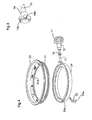
- the Figure 4 is an exploded view of the most important parts of an adjusting device used to control a rotary ring together with the parts belonging to the rotary ring.
- the Figure 5 is a perspective view of an example of a usable coupling in this context.
- an actuating device 1 according to the present invention, a crown body 11, 12.
- This can be made of one piece or be joined together from several, firmly interconnected items, and has an outer crown body 11, which is substantially cup-shaped, and an inner crown body 12.
- the latter is essentially cylindrical and has a smaller outer diameter than the inner diameter of the cup-shaped part of the outer crown body 12, in which it is mounted on.
- the crown body has an annular cavity 19 between its two parts 11, 12.
- a coupling 13, 14 which may have different configurations depending on the purpose, attached to this.
- a crown bushing 15 at least partially surrounds the inner crown body 12 and the coupling 13, 14, these parts being rotatably mounted in the crown bushing.
- the crown bushing 15 is used as usual at a suitable location on the edge of the housing 2 of a clock, wherein the outwardly facing end of the substantially hollow cylindrical crown bushing 15 projects into the annular cavity 19 between outer - and inner crown body 12.
- the adjusting device 1 also has an elastic element 16 which acts on at least one of the crown members 11, 12 in order to bias it in its axial direction.
- the crown body 11, 12 together with parts of the coupling 13, 14 is therefore mounted both axially displaceable and rotatable within the crown bushing 15.
- the biasing force of the elastic element 16 is determined as a function of the effective end face A of the outer crown body 11.
- Such a design of an adjusting device makes it possible to ensure an automatic, axial position switching of the adjusting device in response to the applied external pressure.
- the elastic element may in particular be configured as a helical spring 16, for example, between the crown bushing 15 and the inner crown body 12, a part of the coupling 13, 14 spanning mounted.
- a spring 16 could also be mounted between the crown bushing 15 and the outer crown body 11. It is only important that in the axial direction, a bias of the crown body 11, 12 is generated relative to the fixed to the watch case 2 crown bushing 15.
- This biasing force preferably acts as in illustration 1 shown in the direction of the housing outwardly facing direction, so as to be at normal ambient pressure, a normal position of the actuator to define. At a given, higher external pressure, the crown 11, 12 of the actuator automatically moves into an axially inwardly shifted position, as in Figure 3 is shown.
- a reverse constellation is conceivable in which an inwardly acting biasing force is given, which causes an external displacement of the crown 11, 12 at low external pressure, the chosen constellation will depend on the desired application, as to later Place will be discussed.
- bevel 11 a is mounted so that it does not or only slightly touches the associated sealing ring 17 a in the normal position of the actuator 1, while an automatic axial displacement of the crown 11, 12 to the contact surface 15 a of the crown bushing 15 a Compression of this sealing ring 17a and thus brings an automatic increase in the tightness of the adjusting device 1 with it.
- sealing ring or rings 17 may be attached to the outside of the outwardly facing end of the crown bushing 15 and the bevel 11a cooperating therewith on the inside of the outer crown body 11. This is the case in the present embodiment, which is illustrated in the figures as an example case, where another Sealing ring 18 is mounted between inner crown body 12 and crown bushing 15.
- This embodiment could be chosen otherwise, for example by the sealing rings 17 are arranged on the inside of the outer crown body 11 and the bevel 11 a on the outside of the crown bushing 15, or by one of these arrangements between inner crown body 12 and crown bushing 15 is made while another sealing ring 18 is located approximately on the outer crown body 11.
- the automatic, axial displacement by overcoming the spring biasing force at (pre-) given external pressure in the adjusting device according to the invention can also be used in conjunction with the clutch 13, 14 in an advantageous manner.
- the coupling 13, 14 may be designed such that it is engaged and disengaged by an axial movement of the crown body 11, 12. This is done at a (pre-) certain external pressure by the automatic, axial position switching of the actuator automatic disengagement or engagement, depending on the specific design of the clutch.
- the reproduced in the illustrations coupling has a force applied to the inner crown body 12, approximately screwed, so-called driving screw 13 with teeth 13a at their directed into the housing interior end. It also has a between the drive screw 13 and the crown bushing 15 rotatably mounted gear 14, which has a directed to the teeth 13a of the drive screw 13 Breguetsche side toothing 14a (also called Breguetahnung or saw toothing) on.
- the spring 16 pushes the crown 11, 12 outwards, therefore, the teeth 13a of the driving screw 13 abut on the Breguetschen side toothing 14a of the gear 14, so that the clutch 13, 14 is engaged and a rotation of the outer crown body 11 rotation of the gear 14 causes.
- the coupling instead of a side toothing can be realized by interlocking, polygonal surfaces; other possibilities are included in the prior art.
- the coupling can also be designed so that instead of the automatic disengagement takes place as in the present example, an automatic engagement, for which an arrangement of the side toothing 14a and the teeth 13a of the driving screw 13 at the outwardly directed end of the gear 14 would be sufficient in the example set forth.
- FIG. 4 the adjusting device for controlling an internal, toothed rotary ring 31 is used.
- a work ring 24 which is inserted into a watch case 2 having a housing bottom 21 (bottom) and a housing top 22 ( illustration 1 Its centering takes place by means of a Trolageringes 33, which is under a watch glass 23, while the support of the rotary ring 31 in the housing 2 by means of cover stones 32, for example made of artificially produced ruby, is realized.
- a locking plate 25 a such as artificially made ruby
- the inner rotary ring mechanism 3 is now controlled by the adjusting device 1, insofar as a rotational movement on the outer crown body 11 (in the intended direction of rotation) in the normal position of the device (see illustration 1 ) causes a rotation of the gear 14, which engages in the toothing 31 a of the rotary ring 31 and thus rotates.
- a rotational movement on the outer crown body 11 in the opposite direction causes due to the blocking of the rotary ring 31 in this direction of rotation by the detent spring 25, a locking of the clutch 13, 14, as in Figure 2 shown, so that the rotary ring 31 is not moved in this case.
- a (pre-) given, increased external pressure on the outer crown body 11 finally takes place, an automatic, axial position switching the crown (see Figure 3 ), which has an increased tightness and an automatic disengagement, so that the rotary ring 31 is not adjusted in (accidental) rotation of the outer crown body 11, the result.
- Such an actuator is therefore particularly useful in divers watches, as in this case an unintentional adjustment of the rotary ring for the safety of the diver would be important and must be avoided.
Landscapes
- Physics & Mathematics (AREA)
- General Physics & Mathematics (AREA)
- Electric Clocks (AREA)
- Braking Arrangements (AREA)
Claims (14)
- Dispositif de réglage (1), lequel présente un corps de couronne externe (11), un corps de couronne interne (12) relié de manière fixe à celui-ci, un couplage (13, 14) disposé sur le corps de couronne interne ainsi qu'un tube de couronne (15) enveloppant au moins partiellement le corps de couronne interne (12) et le couplage (13, 14), dans lequel tube le corps de couronne interne (12) est logé de manière à pouvoir coulisser axialement tout comme également à pouvoir tourner, caractérisé en ce qu'il présente un élément élastique (16) exerçant une force de précontrainte sur au moins l'un des corps de couronne (11, 12) en direction axiale de celui-ci, la force de précontrainte de l'élément élastique (16) étant déterminée en fonction de la surface frontale effective (A) du corps de couronne externe (11) afin de permettre un changement de position axiale automatique du dispositif de réglage en fonction de la pression extérieure appliquée.
- Dispositif selon la revendication 1, caractérisé en ce que l'élément élastique est un ressort en spirale (16) disposé entre le tube de couronne (15) et le corps de couronne interne (12).
- Dispositif selon la revendication 1, caractérisé en ce que l'élément élastique est un ressort en spirale (16) disposé entre le tube de couronne (15) et le corps de couronne externe (11).
- Dispositif selon l'une des revendications 1 à 3, caractérisé en ce que l'élément élastique (16) applique une force de précontrainte s'exerçant à partir du tube de couronne (15) vers l'extérieur.
- Dispositif selon l'une des revendications 1 à 4, caractérisé en ce que le corps de couronne externe (11) est essentiellement en forme de pot et en ce que le corps de couronne interne (12) est essentiellement de forme cylindrique et à diamètre plus petit, un espace creux (19) de forme annulaire se trouvant entre les deux parties, lequel est adapté pour la réception d'une extrémité du tube de couronne (15) de forme essentiellement en cylindre creux.
- Dispositif selon la revendication 5, caractérisé en ce qu'au moins une bague d'étanchéité (17, 18) est disposée entre l'extrémité du tube de couronne (15) pénétrant à l'intérieur de l'espace creux de forme annulaire (19) entre les corps de couronne interne (12) et externe (11) et au moins l'un de ces corps, laquelle coopère avec un chanfrein (11a) associé se dressant dans cet espace creux (19) de manière à ce qu'en cas de changement de position axiale automatique du dispositif de réglage, en fonction de la pression extérieure appliquée, une compression de la bague d'étanchéité (17) a lieu pour l'augmentation automatique de l'étanchéité.
- Dispositif selon la revendication 6, caractérisé en ce que la ou les bague(s) d'étanchéité (17) se trouve(nt) sur le côté extérieur du tube de couronne (15) et en ce que le chanfrein (11a) associé se trouve sur le côté intérieur du corps de couronne externe (11).
- Dispositif selon l'une des revendications 1 à 7, caractérisé en ce que les corps de couronne externe (11) et interne (12) sont deux pièces séparées reliées de manière fixe l'une à l'autre.
- Dispositif selon l'une des revendications 1 à 8, caractérisé en ce que le couplage est conçu de manière à pouvoir s'accoupler et se découpler grâce au mouvement axial du corps de couronne externe (12) de manière à ce que, en cas de changement de position axiale automatique du dispositif de réglage, en fonction de la pression extérieure appliquée, un accouplement ou découplement automatique a lieu.
- Dispositif selon la revendication 9, caractérisé en ce que le couplage (13, 14) est conçu de manière à ce qu'une transmission de force a lieu seulement lors de la rotation du corps de couronne externe (11) dans une direction de rotation, alors qu'une rotation dans la direction de rotation contraire produit un débrayage de surcharge du couplage.
- Dispositif selon la revendication 10, caractérisé en ce que le couplage présente une vis entraîneuse (13) disposée sur le corps de couronne interne (12) et une roue dentée (14) montée de manière rotative entre celle-ci et le tube de couronne (15) avec une denture latérale de Bréguet (14a) orientée vers les dents (13a) de la vis entraîneuse (13).
- Dispositif selon l'une des revendications 1 à 11, caractérisé en ce qu'il sert à la commande d'une lunette rotative (31) d'une montre.
- Dispositif selon la revendication 12, caractérisé en ce qu'une roue dentée (14) du couplage est en prise avec une couronne dentée de la lunette rotative (31) afin de produire la rotation de celle-ci.
- Montre, en particulier montre de plongée, caractérisée en ce qu'elle comprend un dispositif de réglage selon l'une des revendications précédentes.
Applications Claiming Priority (2)
| Application Number | Priority Date | Filing Date | Title |
|---|---|---|---|
| CH00090/04A CH697143A5 (de) | 2004-01-23 | 2004-01-23 | Selbsttätige Stellvorrichtung, insbesondere für eine Uhr. |
| CH902004 | 2004-01-23 |
Publications (3)
| Publication Number | Publication Date |
|---|---|
| EP1557728A2 EP1557728A2 (fr) | 2005-07-27 |
| EP1557728A3 EP1557728A3 (fr) | 2009-09-30 |
| EP1557728B1 true EP1557728B1 (fr) | 2013-10-02 |
Family
ID=34624390
Family Applications (1)
| Application Number | Title | Priority Date | Filing Date |
|---|---|---|---|
| EP04026351.9A Expired - Lifetime EP1557728B1 (fr) | 2004-01-23 | 2004-11-05 | Dispositif de correction automatique |
Country Status (4)
| Country | Link |
|---|---|
| US (1) | US7540655B2 (fr) |
| EP (1) | EP1557728B1 (fr) |
| JP (1) | JP4749728B2 (fr) |
| CH (1) | CH697143A5 (fr) |
Families Citing this family (17)
| Publication number | Priority date | Publication date | Assignee | Title |
|---|---|---|---|---|
| US7350968B2 (en) * | 2006-07-14 | 2008-04-01 | Alexander Meerovitsch | Case for a watch movement |
| EP1906268A1 (fr) * | 2006-09-27 | 2008-04-02 | Omega SA | Boîtier de montre à carrure composite |
| ATE475117T1 (de) * | 2007-04-04 | 2010-08-15 | Eta Sa Mft Horlogere Suisse | Aufzugsvorrichtung mit unidirektionale kupplung |
| FR2956755B1 (fr) * | 2010-02-25 | 2012-08-17 | Cheval Freres Sas | Couronne de remontoir de montre multifonctions |
| US8439559B2 (en) * | 2010-03-23 | 2013-05-14 | Bright Aggregation Technology Limited | Timepiece with multi-functional actuator |
| EP2685327B1 (fr) * | 2012-07-09 | 2018-09-05 | Omega SA | Poussoir pour pièce d'horlogerie incorporant une soupape |
| USD740710S1 (en) * | 2013-08-06 | 2015-10-13 | Marco Gatti | Bracelet |
| USD740709S1 (en) * | 2013-08-06 | 2015-10-13 | Marco Gatti | Bracelet |
| CH708755A1 (de) * | 2013-10-30 | 2015-04-30 | Richemont Int Sa | Halte- und Indexierungsvorrichtung für Uhren. |
| USD725529S1 (en) * | 2013-12-20 | 2015-03-31 | Rolex Watch U.S.A., Inc. | Watch bezel |
| JP6424048B2 (ja) * | 2014-09-09 | 2018-11-14 | セイコーインスツル株式会社 | 時計 |
| JP6367059B2 (ja) * | 2014-09-09 | 2018-08-01 | セイコーインスツル株式会社 | 時計 |
| CN107976891A (zh) * | 2018-01-17 | 2018-05-01 | 出门问问信息科技有限公司 | 一种防水结构及智能手表 |
| HK1252182A2 (zh) * | 2018-07-06 | 2019-05-17 | Pengelly Co. Ltd. | 有几何代码的手表 |
| KR102888835B1 (ko) | 2021-02-22 | 2025-11-21 | 삼성전자주식회사 | 방수 구조 및 이를 포함하는 전자 장치 |
| EP4160321B1 (fr) * | 2021-09-29 | 2025-09-03 | ETA SA Manufacture Horlogère Suisse | Cercle de protection pour mouvement horloger et mouvement horloger comportant ledit cercle de protection |
| CN117160848A (zh) * | 2023-10-17 | 2023-12-05 | 南通莱欧电子科技有限公司 | 一种加工用分拣装置 |
Citations (1)
| Publication number | Priority date | Publication date | Assignee | Title |
|---|---|---|---|---|
| EP0556155A1 (fr) * | 1992-02-12 | 1993-08-18 | Montres Rolex Sa | Dispositif de commande étanche pour montre |
Family Cites Families (16)
| Publication number | Priority date | Publication date | Assignee | Title |
|---|---|---|---|---|
| FR1027587A (fr) * | 1950-11-13 | 1953-05-13 | Francois Miserez Ets | Boîtier de montre-bracelet à cadran tournant formant calendrier perpétuel |
| DE1298935B (de) * | 1965-07-14 | 1969-07-03 | Piquerez Sa Ervin | Uhr mit Anzeigering |
| CH457291A (fr) * | 1966-02-01 | 1967-12-29 | Couronnes Boninchi S A Fab De | Poussoir étanche pour montre de plongeur |
| US3376701A (en) * | 1966-07-01 | 1968-04-09 | United States Time Corp.:The | Watch crown |
| US3485036A (en) * | 1967-07-07 | 1969-12-23 | Walther A Feurer | High pressure watertight watch crown |
| US3418800A (en) * | 1967-10-04 | 1968-12-31 | Seiko Instr & Electronics | Crowns comprising push-button inside of them |
| CH1885268A4 (fr) * | 1968-12-18 | 1971-02-15 | Omega Brandt & Freres Sa Louis | Organe de commande étanche pour montre |
| CH569318B5 (fr) * | 1973-06-29 | 1975-11-14 | Soguel Rene | |
| JPS63187091A (ja) * | 1987-01-28 | 1988-08-02 | 三菱マテリアル株式会社 | ロ−タリキルンの焚口構造 |
| DE4010837C1 (fr) * | 1990-04-04 | 1991-07-25 | Manufacture Jaeger-Le Coultre S.A., Le Sentier, Ch | |
| CH682874B5 (fr) * | 1992-02-07 | 1994-06-15 | Smh Management Services Ag | Bouton-poussoir pour pièce d'horlogerie de plongeur. |
| US6010241A (en) * | 1996-04-12 | 2000-01-04 | Enigma S.A. | Watch |
| CH691936A5 (de) * | 1997-06-11 | 2001-11-30 | Meco Sa Grenchen | Betätigungsmittel mit Dichtung für eine Uhr. |
| FR2786574B1 (fr) * | 1998-11-30 | 2001-02-16 | Ebel Sa | Joint d'etancheite et dispositif de commande etanche d'une piece d'horlogerie |
| US6896403B1 (en) * | 2002-12-30 | 2005-05-24 | Timex Group B.V. | Mode selecting assembly for a timepiece |
| WO2005038538A1 (fr) * | 2003-10-21 | 2005-04-28 | Richemont International Sa | Dispositif de commande a couronne-poussoir pour montre |
-
2004
- 2004-01-23 CH CH00090/04A patent/CH697143A5/de not_active IP Right Cessation
- 2004-11-05 EP EP04026351.9A patent/EP1557728B1/fr not_active Expired - Lifetime
-
2005
- 2005-01-19 US US11/037,165 patent/US7540655B2/en active Active
- 2005-01-20 JP JP2005013065A patent/JP4749728B2/ja not_active Expired - Fee Related
Patent Citations (1)
| Publication number | Priority date | Publication date | Assignee | Title |
|---|---|---|---|---|
| EP0556155A1 (fr) * | 1992-02-12 | 1993-08-18 | Montres Rolex Sa | Dispositif de commande étanche pour montre |
Also Published As
| Publication number | Publication date |
|---|---|
| HK1076313A1 (zh) | 2006-01-13 |
| EP1557728A3 (fr) | 2009-09-30 |
| US20050162985A1 (en) | 2005-07-28 |
| JP2005208060A (ja) | 2005-08-04 |
| US7540655B2 (en) | 2009-06-02 |
| CH697143A5 (de) | 2008-05-15 |
| EP1557728A2 (fr) | 2005-07-27 |
| JP4749728B2 (ja) | 2011-08-17 |
Similar Documents
| Publication | Publication Date | Title |
|---|---|---|
| EP1557728A2 (fr) | Dispositif de correction automatique | |
| EP2869136B1 (fr) | Dispositif de maintien et d'indexage pour pièces d'horlogerie | |
| CH700807B1 (de) | Zeitmesser. | |
| CH699427B1 (de) | Tragbarer Zeitmesser. | |
| DE202009001440U1 (de) | Kraftgetriebenes Handwerkzeug mit Spanneinrichtung für ein Werkzeug | |
| DE102014104119B4 (de) | Anschlagkörper für Tür- und/oder Fenstergriffe und Griffanordnung mit einem Anschlagkörper | |
| CH708307B1 (de) | Tragbarer Zeitmesser und Verfahren zur Herstellung der Krone des Zeitmessers. | |
| DE3125458A1 (de) | Drehscharnier | |
| DE102010038036B4 (de) | Ventilkörperabdeckung eines Automatikgetriebes | |
| DE102006047480B4 (de) | Kugelmühle mit Mitnahmemitteln für eine formschlüssige Verbindung zwischen Mahlgefäß und Aufnahmevorrichtung | |
| DE7710413U1 (de) | Vorrichtung zur anzeige der stellung eines betaetigungsgliedes | |
| CH697487B1 (de) | Tragbarer Zeitmesser. | |
| DE10006326A1 (de) | Handantrieb für Absperrorgane | |
| DE69701136T2 (de) | Uhr | |
| CH697818B1 (de) | Uhr. | |
| DE102005059182A1 (de) | Betriebsartenumschalter zum Einstellen mindestens einer Betriebsart in einer Handwerkzeugmaschine | |
| DE3023940A1 (de) | Mischventil zur steuerung eines wasserstromes | |
| DE102019220577A1 (de) | Federungssystem für ein fahrrad | |
| DE9300841U1 (de) | Sanitärarmatur | |
| DE8804833U1 (de) | Zeitabhängig schaltende Schaltvorrichtung | |
| CH714989B1 (de) | Kronenmechanismus. | |
| DE3023939A1 (de) | Mischventil zur steuerung eines wasserstromes | |
| CH714912B1 (de) | Uhr mit Kupplung zwischen drehbarem Aussenring und Stellwelle. | |
| DE102023127288A1 (de) | Sanitärarmatur | |
| DE60313483T2 (de) | Vorrichtung zur kupplung eines zahnrades |
Legal Events
| Date | Code | Title | Description |
|---|---|---|---|
| PUAI | Public reference made under article 153(3) epc to a published international application that has entered the european phase |
Free format text: ORIGINAL CODE: 0009012 |
|
| AK | Designated contracting states |
Kind code of ref document: A2 Designated state(s): AT BE BG CH CY CZ DE DK EE ES FI FR GB GR HU IE IS IT LI LU MC NL PL PT RO SE SI SK TR |
|
| AX | Request for extension of the european patent |
Extension state: AL HR LT LV MK YU |
|
| REG | Reference to a national code |
Ref country code: HK Ref legal event code: DE Ref document number: 1076313 Country of ref document: HK |
|
| RIC1 | Information provided on ipc code assigned before grant |
Ipc: G04B 27/00 20060101AFI20050601BHEP Ipc: G04B 37/04 20060101ALI20090513BHEP Ipc: G04B 37/10 20060101ALI20090513BHEP |
|
| PUAL | Search report despatched |
Free format text: ORIGINAL CODE: 0009013 |
|
| AK | Designated contracting states |
Kind code of ref document: A3 Designated state(s): AT BE BG CH CY CZ DE DK EE ES FI FR GB GR HU IE IS IT LI LU MC NL PL PT RO SE SI SK TR |
|
| AX | Request for extension of the european patent |
Extension state: AL HR LT LV MK YU |
|
| 17P | Request for examination filed |
Effective date: 20100322 |
|
| AKX | Designation fees paid |
Designated state(s): CH DE FR GB LI |
|
| 17Q | First examination report despatched |
Effective date: 20100518 |
|
| GRAP | Despatch of communication of intention to grant a patent |
Free format text: ORIGINAL CODE: EPIDOSNIGR1 |
|
| INTG | Intention to grant announced |
Effective date: 20130507 |
|
| GRAS | Grant fee paid |
Free format text: ORIGINAL CODE: EPIDOSNIGR3 |
|
| GRAA | (expected) grant |
Free format text: ORIGINAL CODE: 0009210 |
|
| AK | Designated contracting states |
Kind code of ref document: B1 Designated state(s): CH DE FR GB LI |
|
| REG | Reference to a national code |
Ref country code: GB Ref legal event code: FG4D Free format text: NOT ENGLISH |
|
| REG | Reference to a national code |
Ref country code: CH Ref legal event code: EP |
|
| REG | Reference to a national code |
Ref country code: CH Ref legal event code: NV Representative=s name: THOMAS SAMMER ET AL. PER MENS INTELLECTUAL PRO, CH |
|
| REG | Reference to a national code |
Ref country code: DE Ref legal event code: R096 Ref document number: 502004014378 Country of ref document: DE Effective date: 20131128 |
|
| REG | Reference to a national code |
Ref country code: HK Ref legal event code: GR Ref document number: 1076313 Country of ref document: HK |
|
| REG | Reference to a national code |
Ref country code: DE Ref legal event code: R097 Ref document number: 502004014378 Country of ref document: DE |
|
| PLBE | No opposition filed within time limit |
Free format text: ORIGINAL CODE: 0009261 |
|
| STAA | Information on the status of an ep patent application or granted ep patent |
Free format text: STATUS: NO OPPOSITION FILED WITHIN TIME LIMIT |
|
| 26N | No opposition filed |
Effective date: 20140703 |
|
| REG | Reference to a national code |
Ref country code: DE Ref legal event code: R097 Ref document number: 502004014378 Country of ref document: DE Effective date: 20140703 |
|
| REG | Reference to a national code |
Ref country code: FR Ref legal event code: PLFP Year of fee payment: 12 |
|
| REG | Reference to a national code |
Ref country code: FR Ref legal event code: PLFP Year of fee payment: 13 |
|
| REG | Reference to a national code |
Ref country code: FR Ref legal event code: PLFP Year of fee payment: 14 |
|
| PGFP | Annual fee paid to national office [announced via postgrant information from national office to epo] |
Ref country code: GB Payment date: 20221125 Year of fee payment: 19 Ref country code: FR Payment date: 20221128 Year of fee payment: 19 Ref country code: DE Payment date: 20221123 Year of fee payment: 19 |
|
| PGFP | Annual fee paid to national office [announced via postgrant information from national office to epo] |
Ref country code: CH Payment date: 20221114 Year of fee payment: 19 |
|
| REG | Reference to a national code |
Ref country code: DE Ref legal event code: R119 Ref document number: 502004014378 Country of ref document: DE |
|
| REG | Reference to a national code |
Ref country code: CH Ref legal event code: PL |
|
| PG25 | Lapsed in a contracting state [announced via postgrant information from national office to epo] |
Ref country code: CH Free format text: LAPSE BECAUSE OF NON-PAYMENT OF DUE FEES Effective date: 20231130 |
|
| GBPC | Gb: european patent ceased through non-payment of renewal fee |
Effective date: 20231105 |
|
| PG25 | Lapsed in a contracting state [announced via postgrant information from national office to epo] |
Ref country code: CH Free format text: LAPSE BECAUSE OF NON-PAYMENT OF DUE FEES Effective date: 20231130 |
|
| PG25 | Lapsed in a contracting state [announced via postgrant information from national office to epo] |
Ref country code: DE Free format text: LAPSE BECAUSE OF NON-PAYMENT OF DUE FEES Effective date: 20240601 |
|
| PG25 | Lapsed in a contracting state [announced via postgrant information from national office to epo] |
Ref country code: GB Free format text: LAPSE BECAUSE OF NON-PAYMENT OF DUE FEES Effective date: 20231105 |
|
| PG25 | Lapsed in a contracting state [announced via postgrant information from national office to epo] |
Ref country code: FR Free format text: LAPSE BECAUSE OF NON-PAYMENT OF DUE FEES Effective date: 20231130 |
|
| PG25 | Lapsed in a contracting state [announced via postgrant information from national office to epo] |
Ref country code: GB Free format text: LAPSE BECAUSE OF NON-PAYMENT OF DUE FEES Effective date: 20231105 Ref country code: FR Free format text: LAPSE BECAUSE OF NON-PAYMENT OF DUE FEES Effective date: 20231130 Ref country code: DE Free format text: LAPSE BECAUSE OF NON-PAYMENT OF DUE FEES Effective date: 20240601 |