EP1558859B1 - Dispositif de suspension et d'amortissement - Google Patents
Dispositif de suspension et d'amortissement Download PDFInfo
- Publication number
- EP1558859B1 EP1558859B1 EP03810440A EP03810440A EP1558859B1 EP 1558859 B1 EP1558859 B1 EP 1558859B1 EP 03810440 A EP03810440 A EP 03810440A EP 03810440 A EP03810440 A EP 03810440A EP 1558859 B1 EP1558859 B1 EP 1558859B1
- Authority
- EP
- European Patent Office
- Prior art keywords
- springing
- dampening
- spring
- friction
- lever
- Prior art date
- Legal status (The legal status is an assumption and is not a legal conclusion. Google has not performed a legal analysis and makes no representation as to the accuracy of the status listed.)
- Expired - Lifetime
Links
Images
Classifications
-
- F—MECHANICAL ENGINEERING; LIGHTING; HEATING; WEAPONS; BLASTING
- F16—ENGINEERING ELEMENTS AND UNITS; GENERAL MEASURES FOR PRODUCING AND MAINTAINING EFFECTIVE FUNCTIONING OF MACHINES OR INSTALLATIONS; THERMAL INSULATION IN GENERAL
- F16H—GEARING
- F16H7/00—Gearings for conveying rotary motion by endless flexible members
- F16H7/08—Means for varying tension of belts, ropes or chains
- F16H7/10—Means for varying tension of belts, ropes or chains by adjusting the axis of a pulley
- F16H7/12—Means for varying tension of belts, ropes or chains by adjusting the axis of a pulley of an idle pulley
- F16H7/1209—Means for varying tension of belts, ropes or chains by adjusting the axis of a pulley of an idle pulley with vibration damping means
- F16H7/1218—Means for varying tension of belts, ropes or chains by adjusting the axis of a pulley of an idle pulley with vibration damping means of the dry friction type
-
- F—MECHANICAL ENGINEERING; LIGHTING; HEATING; WEAPONS; BLASTING
- F16—ENGINEERING ELEMENTS AND UNITS; GENERAL MEASURES FOR PRODUCING AND MAINTAINING EFFECTIVE FUNCTIONING OF MACHINES OR INSTALLATIONS; THERMAL INSULATION IN GENERAL
- F16H—GEARING
- F16H7/00—Gearings for conveying rotary motion by endless flexible members
- F16H7/08—Means for varying tension of belts, ropes or chains
- F16H2007/0802—Actuators for final output members
- F16H2007/081—Torsion springs
-
- F—MECHANICAL ENGINEERING; LIGHTING; HEATING; WEAPONS; BLASTING
- F16—ENGINEERING ELEMENTS AND UNITS; GENERAL MEASURES FOR PRODUCING AND MAINTAINING EFFECTIVE FUNCTIONING OF MACHINES OR INSTALLATIONS; THERMAL INSULATION IN GENERAL
- F16H—GEARING
- F16H7/00—Gearings for conveying rotary motion by endless flexible members
- F16H7/08—Means for varying tension of belts, ropes or chains
- F16H2007/0863—Finally actuated members, e.g. constructional details thereof
- F16H2007/0874—Two or more finally actuated members
Definitions
- the present invention relates to a spring and damping device for damping springs of the rotary or pivoting movement of at least one rotatable or pivotable and resiliently mounted lever arm.
- the invention relates to a spring and damping device which is integrated in a tensioning device for a traction means such as a belt or chain.
- a spring and damping device of the aforementioned type can be used in a variety of arrangements or systems in which a rotational movement to one spring, to be attenuated to the other.
- a spring and damping device can be used in a tensioning device for a traction mechanism of a traction mechanism in which the pivoting movement of at least one tensioning arm with tensioning means, for example a tensioning pulley, has to be cushioned and also damped for tensioning a run of the traction means.
- a change occurs between the traction strand and the slack side.
- a Trum mirror takes place for example in a belt drive, which includes a starter generator and a crankshaft of an engine.
- a belt drive is operated in a starting mode and a generator mode.
- a strand is a trailing or empty strand.
- the tension of the belt must be adjusted depending on the operating mode at different runs.
- a strand indicates that part of the traction means which lies between two adjacent deflection rollers.
- the pulleys in particular Pulleys, but may not be connected to aggregates to their drive.
- crankshaft revolutions are subject to nonuniformities that may be particularly noticeable at high powers and low crankshaft speeds.
- the consequence of these rotational irregularities are alternating torques which are transmitted to the belt drive and cause acceleration or deceleration in the traction means there.
- Such delays or accelerations are then also transferred to ancillary units, which are driven by the belt drive. Frequently, however, there is the requirement that the ancillaries work with the most uniform speeds possible.
- the DE 199 26 612 A1 that mentioned in the DE 42 43 451 A1
- a belt drive in which a so-called starter generator is arranged in the belt drive.
- two clamping arms are shown with tension rollers, wherein the clamping arms are pressed towards each other by a tension spring.
- the tension rollers are arranged outside of the area spanned by the belt.
- the common axis of rotation of the clamping arms is located within the area spanned by the belt. This should be the respect of the DE 42 43 451 A1 described disadvantages are avoided.
- a belt drive is disclosed, in particular for internal combustion engines for driving ancillaries of a vehicle.
- This known belt drive has in the usual way at least two pulleys. Both on the slack side as well as on the load is in each case a tension roller under spring force. This makes it possible, for example, to transmit torques in both directions and thus to use the generator of an internal combustion engine as a starter.
- the two tension rollers can support each other elastically, for example, by a biased arranged between them Spring, in particular a tension spring.
- this embodiment with a tension spring is relatively complicated according to the disclosed embodiments and damping is not apparent.
- a belt tensioning device with lamellar sliding bearing ring is made of DE 44 28 560 A1 known.
- a sliding bearing ring is arranged between a housing-fixed pivot axis and a tension sleeve fixed sleeve.
- the tensioning arm is frictionally coupled to a housing via a torsion bar spring and a radial flange connected non-rotatably to this torsion bar spring.
- a helical torsion spring concentrically arranged on the torsion bar spring couples the tension arm to the housing.
- the DE 44 31 801 A1 shows a clamping device with directional damper.
- a clamping arm is coupled via a torsion bar spring with a housing part.
- a friction disc is provided between one end of the torsion bar spring and the housing.
- a torsion spring is concentric with the torsion bar spring and urges the tension arm away from the housing so that the torsion bar spring and the flange attached thereto are pressed against the friction disc.
- a pivot bearing known with the two mutually rotatably mounted machine parts are rotatably coupled to each other via a band spring.
- a friction ring is inserted between a foot part and a support body with spring preload, which is generated by a crimped into a pot sleeve plate spring.
- the generic is still DE 3912944 A1 to be mentioned, which discloses a belt tensioning device in which at least one tensioning element, a tensioning lever and provided at the free end of the tensioning lever tensioning pulley or tensioning pulley is present.
- the clamping element is designed as a torsion bar.
- three torsion bars are provided, which have the largest possible contact surface.
- the technical problem underlying the invention is to provide a spring and damping device that springs in a compact design and technically simple and cost-effective rotational and pivotal movement and dampens.
- a spring and damper device for springing and damping the rotational movement of at least one pivotally and resiliently mounted lever arm.
- the spring and damping device comprises a first lever arm which is rotatably mounted or pivotable about a rotation axis.
- a longitudinally extending axis of rotation claimed to torsion spring means having two spaced-apart Federend Suitee, of which a first Federend Scheme is rotatably connected to the first lever arm.
- At least one damping element is on the hollow cylinder, inside or outside, rotationally fixed, but slidably disposed in the direction of the axis of rotation and with the second Federend Geb the claimed on torsion spring means rotatably connected.
- At least one friction element is for damping a rotational movement with the damping element in frictional contact.
- a spring presses against the at least one damping element and thus causes a predetermined friction torque between the damping element and the friction element for damping the rotational movement.
- spring end region is to be understood, in particular, as that region of the spring means subjected to torsion, which does not provide the actual contribution of the torsion suspension.
- the invention is based on the fundamental idea, for the first time a very compact construction and in particular a small diameter exhibiting, claimed on torsion spring means to provide suspension of at least one lever arm and nachzutouch this spring means a damping.
- a spring and damping device can be achieved with a small diameter and a compact shape.
- the technical complexity is low, whereby the manufacturing cost can be reduced.
- the at least one friction element is pressed against the damping element by means of a spring.
- the damping element may for example be a non-rotatably connected to the spring means disc, acting on the side surfaces of one or more friction elements, similar to a disc brake.
- the friction element for example, as part of a holder in which the hollow cylinder is rotatably mounted.
- the spring is supported here against a fixedly mounted on the hollow cylinder support member or against another part of the holder.
- a hollow cylinder is present in the interior of which the torsion-stressed spring means is housed.
- the hollow cylinder is rotatably connected to the second Federend Scheme of the spring means.
- damping elements There are now two damping elements on the hollow cylinder against rotation, but slidably disposed in the direction of the axis of rotation.
- a spring is arranged, which presses the two damping elements away from each other, each against a friction element and thus causes a predetermined friction between each of a damping element and a friction element.
- the friction elements may each be part of a holder for the hollow cylinder.
- the parts of the holder which act as friction elements, the facing inner sides of a kind of fork with through holes for receiving the hollow cylinder.
- the damping elements each have a conical surface as a friction surface, which are each in frictional contact with correspondingly shaped friction surfaces of the friction elements.
- the friction surfaces can be increased and thus increase the damping.
- a further exemplary embodiment provides that a second lever arm is provided which, like the first lever arm, is rotatably mounted about the axis of rotation. It should be emphasized that the second lever is also rotatable about the same axis of rotation as the first lever arm. But the second lever arm is then rotatably connected to the damping element, so for example with a cylinder end of the aforementioned hollow cylinder. This makes it possible for the To arrange two levers on the same side of the spring means, but to connect the two levers resiliently via the spring means and the hollow cylinder.
- the torsion spring is a torsionally stressed spring means.
- the claimed torsion spring means of one or more leaf springs constructed.
- the adjacent sides of the leaf springs rub against each other during a rotation and thus not only cushion the rotational movement, but also damp it at the same time.
- the damping element in particular the hollow cylinder, which is connected in a rotationally fixed manner to the spring means in a holder.
- the one or more damping elements are integrated in the holder.
- the holder and the damping elements made of aluminum or cast steel.
- the damping elements could also be used in the holder socket made of a suitable material, such as plastic bushings.
- a lever arm or both lever arms may be formed as a tensioning arm with tensioning means arranged thereon.
- tensioning means in particular tension rollers are used.
- a tensioning device with the spring and damping device according to one of the preceding embodiments outside the inner surface, which is enclosed by a belt, be arranged, so that the clamping means of Pressed externally on the belt, in which case the axis of rotation of the clamping lever can lie inside or outside the belt-enclosed inner surface.
- a further exemplary embodiment provides that the spring and damping device or clamping device is provided according to one of the preceding Ausfiihrungsbei admira for a traction mechanism, which includes the drive of a starter generator and possibly other aggregates.
- the traction means a belt, wraps around or connects the pulleys.
- a first tensioning means such as a tensioning arm with tension roller, is tensioned against the outside of the run between the pulley of the motor and the pulley of the starter generator.
- a second clamping means can be tensioned on the strand between the pulley of the starter generator and, for example, the pulley of a further unit.
- the tension is generated by the torsion-stressed spring means, in particular a multilayer leaf spring packet, the damping via the previously described damping means and friction means.
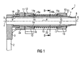
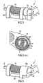
- a first exemplary embodiment of a spring and damping device according to the invention, which is integrated in a tensioning device 1, is in the Fig. 1 to 4 shown.
- the clamping device 1 comprises two clamping arms 2, 3, to each of which at a free end a tensioning roller 22, 23 is arranged freely rotatable.
- the clamping or lever arm 2 has at the opposite end of the tensioning roller 23 an eye 2 a, in which a through hole is introduced.
- the other clamping arm 3 also has on the associated tension roller 22 opposite free end an eye 3a, in which also a through hole is present.
- This through hole is stepped, so that a larger diameter hole and a smaller diameter hole, as in the Fig. 1 can be seen, in the eye 3a is present.
- rotation spring means 4 for example, a torsion bar, rotatably pressed.
- the clamping arm 3 and the claimed torsion spring means 4 may be rotatably connected to each other by positive engagement or by form and frictional engagement.
- a Dahlnutprofil in the end region 5 and a corresponding counter-profile in the eye 3a of the clamping lever 3 for non-rotatable connection of the two elements 3, 4 conceivable.
- the stressed on torsion spring 4 is elongated and has a further free Federend Scheme 6.
- This spring end region 6 is rotatably connected to a hollow cylinder 7.
- the hollow cylinder 7 has a compressed cylinder end 8 which frictionally engages the spring end region 6 of the spring means 4 embraces. Under certain circumstances, a frictional and / or positive connection can also be carried out.
- the claimed torsion spring means 4 is rotatably connected to the cylinder end 8 of the hollow cylinder 7.
- the hollow cylinder 7 is pushed over the spring means 4, so that the spring means is at least largely accommodated in the interior of the hollow cylinder 7, which allows a compact design.
- the other cylinder end 9 of the hollow cylinder 7 extends into the stepped bore in the eye 3a of the clamping arm 3.
- the clamping or lever arm 3 is rotatably mounted on the hollow cylinder 7.
- the cylinder end 9 of the hollow cylinder 7 is turned off by a certain amount on the outer circumference, so that a socket 10 is properly to take care of it and a perfect sliding fit of the sleeve 10 and the clamping arm 3 is ensured.
- the eye sits 2a of the clamping arm 2 also on the hollow cylinder 7 in the region of the cylinder end 9.
- the eye 2a has for this purpose an outside stepped bore in which the eye 3a of the clamping arm 3 is partially inserted.
- the eye 2a of the clamping arm 2 is rotatably mounted on the hollow cylinder 7, for example by pressing. Again, of course, a positive connection between the two elements 2, 7 are provided.
- clamping arm 2 and the clamping arm 3 are resiliently coupled about the common axis of rotation Z by means of the spring means 4 with respect to a pivoting movement of one of the clamping arms 2, 3.
- the suspension is softer or harder.
- the spring stiffness can by appropriate choice of material or dimensioning of the spring means 4 to the respective intended use of the clamping device. 1 be adjusted. A compact design is still achievable. In particular, the diameter of such a spring coupling is low. An extremely cost-effective and effective measure for determining the spring stiffness of the spring means 4 is not to perform the spring means 4 as known per se Torsionsfederstab, but build up of stacked leaf springs 4a, 4b, 4c.
- the spring means 4 consists of three superimposed leaf springs 4a, 4b, 4c, rubbing relative to each other about the rotation axis 6 at a rotation of the clamping arms 2, 3 and thus not only a suspension but also a damping of the relative rotational movement of the two clamping arms makes each other.
- Fig. 1 are between the cylinder end 8 and the cylinder end 9 on the hollow cylinder 7 two plastic cones 14, 15 spaced on the outer circumference of the hollow cylinder 7 from each other.
- the cones 14, 15 are arranged non-rotatably on the hollow cylinder 7, but in the longitudinal direction, that is displaceable in the direction of the axis of rotation Z.
- one or more longitudinal grooves may be formed or milled on the outer circumference of the hollow cylinder 7, in which corresponding springs fit on the inner peripheries of the plastic cones 14, 15.
- the two plastic cones 14, 15 each have conical surfaces which, as in the Fig. 1 shown, facing away from each other.
- the conical surfaces of the plastic cones 14, 15 facing away from end faces 14a, 15a receiving seats for each support ring 16, 17 are provided, on which press the ends 18a, 18b of a coil spring designed as a compression spring 18.
- the compression spring 18 By the compression spring 18, the plastic cones 14, 15 from each other pushed away.
- the cones 14, 15 are guided in the groove profiles, that is, along the axis of rotation Z.
- On the conical surfaces of the plastic cones 14, 15 sit respectively shaped friction elements 12, 13, which have corresponding conical inner holes.
- the friction elements 12, 13 are formed as part of a holder 20, which in particular from the perspective view according to the Fig.
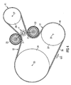
- This first exemplary embodiment of the invention can, as in the Fig. 4 shown to be arranged outside of a belt drive.
- the Indian Fig. 4 The belt drive shown comprises a belt 30, which wraps around a pulley 24 of an internal combustion engine, which sits on the crankshaft 25. Further, the belt drive connects an air conditioning compressor 40 present, which has a rotation axis 29, on which a pulley 28 is seated. The pulley 28 is also looped by the belt 30. Finally, a starter generator 41 is present, which comprises a pulley 26 which sits on a rotation axis 27 of the starter generator 41. Also, this pulley 26 is looped by the belt 30. Outside, in the Fig. 4 "obliquely above" the axis of rotation 27 of the starter generator 41, the axis of rotation Z of the clamping device 1 is arranged. The clamping arms 2, 3 and the respective associated tension rollers 22, 23 touch the belt 30 from the outside.
- the motor drives the belt 30 - the pulley 24 is the traction sheave and the pulley 26 of the starter generator 41, the electrical supply is ensured.
- the tensioning roller 23 is now looped around by the belt 30 over a larger disk circumference, whereas the tensioning roller 23 of the tensioning arm 3 is virtually not wrapped around.
- the vibrations occurring during operation which can be felt in rotational movements of the clamping arms 2, 3, are cushioned by the spring means 4 and both by the internal friction in the claimed torsion spring means 4 and by the separate damping device with the plastic cones 14, 15th , the intermediate coil spring 18 and the friction elements 12, 13 damped.
- FIG Fig. 5 Another exemplary embodiment of the invention is shown in FIG Fig. 5 shown. This corresponds to the tension arm 2 in the Fig. 2 shown embodiment.
- a support 50 is present, which has an eye 50a, in which the hollow cylinder 7 is pressed in non-rotatably.
- the support 50 is like the holder 20 fixedly mounted on a housing or vehicle part.
- the housing of the starter generator 41 can be provided for fastening the holder 20 and the support.
- the support 50 could also be formed integrally with the holder 20.
Landscapes
- Engineering & Computer Science (AREA)
- General Engineering & Computer Science (AREA)
- Mechanical Engineering (AREA)
- Devices For Conveying Motion By Means Of Endless Flexible Members (AREA)
Claims (15)
- Dispositif de suspension et d'amortissement pour suspendre et amortir le mouvement pivotant d'au moins un bras de levier (2, 3) pivotant et monté sur ressort, avec- un premier bras de levier (3), qui est monté avec liberté de pivoter autour d'un axe de rotation (Z),- un élément élastique (4) s'étendant le long de l'axe de rotation (Z), soumis à un effort de torsion, présentant deux régions élastiques séparées l'une de l'autre (5, 6), desquelles une première région (5) est solidaire du premier bras de levier (3), caractérisé en ce que le dispositif de suspension et d'amortissement comprend- un cylindre creux (7), dans la cavité interne duquel est logé l'élément élastique (4) soumis à un effort de torsion, et qui est solidaire sur une section cylindrique (8) de la deuxième région élastique (6) de l'élément élastique (4),- au moins un élément amortisseur (14, 15), solidaire du cylindre creux (7), mais libre de se mouvoir dans le sens de l'axe de rotation (Z), est solidaire de la deuxième région élastique (6) de l'élément élastique de torsion (4),- au moins un élément de friction (12, 13), lequel est en contact par friction avec l'élément amortisseur (7, 14, 15) afin d'amortir un mouvement de rotation, et- un ressort (18), lequel appuie contre au moins l'élément amortisseur (14, 15), et génère ainsi un moment de friction prédéfini entre l'élément amortisseur (14, 15) et l'élément de friction (12, 13) pour amortir le mouvement de rotation.
- Dispositif de suspension et d'amortissement selon la revendication n° 1
caractérisé en ce que- deux éléments amortisseurs (14, 15), sont solidaires du cylindre creux (7), mais libres de se mouvoir dans le sens de l'axe de rotation (Z), et- le ressort (18) est disposé entre les deux éléments amortisseurs (14, 15), de telle sorte que le ressort (18) pousse les deux éléments amortisseurs (14, 15) loin l'un de l'autre et contre chaque fois un élément de friction (12, 13), et génère ainsi un moment de friction prédéfini entre chaque élément amortisseur (14, 15) et l'élément de friction (12, 13) correspondant. - Dispositif de suspension et d'amortissement selon l'une des revendications précédentes caractérisé en ce que les éléments de friction (14, 15) présentent chacun une jupe conique servant de surface de friction, en contact par friction avec des surfaces correspondantes des éléments de friction (12, 13).
- Dispositif de suspension et d'amortissement selon l'une des revendications n° 1 à 3, caractérisé en ce qu'au moins un élément de friction (12, 13) fait partie d'un support (20) dans lequel le cylindre creux (7) est disposé avec liberté de pivoter.
- Dispositif de suspension et d'amortissement selon l'une des revendications précédentes, caractérisé en ce qu'un deuxième bras de levier (2) est présent, lequel est libre de pivoter autour de l'axe de rotation (Z) comme le bras de levier (3).
- Dispositif de suspension et d'amortissement selon la revendication n° 5, caractérisé en ce que le deuxième bras de levier (2) est solidaire de l'élément amortisseur (14, 15).
- Dispositif de suspension et d'amortissement selon la revendication n° 5 ou la revendication n° 6, caractérisé en ce que le deuxième bras de levier (2) est solidaire du cylindre creux (7).
- Dispositif de suspension et d'amortissement selon une ou plusieurs des revendications précédentes, caractérisé en ce que l'élément élastique (4) est constitué d'une ou de plusieurs lames-ressort (4a, 4b, 4c).
- Dispositif de suspension et d'amortissement selon l'une des revendications précédentes, caractérisé en ce que le cylindre creux (7) solidaire de l'élément élastique (4) soumis à un effort de torsion est monté dans un support (12, 13, 20) avec liberté de pivoter.
- Dispositif de suspension et d'amortissement selon l'une des revendications précédentes, caractérisé en ce que les éléments de friction (12, 13) sont intégrés au support (20).
- Dispositif de suspension et d'amortissement selon l'une des revendications précédentes, caractérisé en ce qu'un ou les deux bras de levier sont formés comme levier tendeur (2, 3) avec dispositif de tension (22, 23) disposé sur le levier, et les dispositifs de tension (22, 23) sont constitués pour tendre une courroie (30) dans un entraînement à courroie.
- Dispositif de suspension et d'amortissement selon la revendication n° 11, caractérisé en ce que la courroie (30) entoure une surface interne et le dispositif de suspension et d'amortissement est disposé à l'extérieur de la surface interne.
- Dispositif de suspension et d'amortissement selon la revendication n° 12, caractérisé en ce que la courroie (30) appartient à une transmission à courroie d'un moteur, en particulier un moteur à combustion interne, comprenant l'entraînement d'un démarreur alternateur (41) et d'au moins un groupe (40) supplémentaire.
- Dispositif de suspension et d'amortissement selon la revendication n° 13, caractérisé en ce que la courroie (30) enlace une poulie (24) du moteur, une poulie (26) du démarreur-alternateur (41) et une poulie du groupe (40) et qu'un élément tendeur (23) appuie contre la section située entre la poulie (24) du moteur et la poulie (26) du démarreur-alternateur (41), et qu'un élément tendeur (22) appuie contre la section située entre la poulie (28) du groupe (40) et la poulie (26) du démarreur-alternateur (41).
- Dispositif de suspension et d'amortissement selon la revendication n° 13 ou la revendication n°14, caractérisé en ce que le groupe est constitué du compresseur d'un climatiseur (40).
Applications Claiming Priority (3)
| Application Number | Priority Date | Filing Date | Title |
|---|---|---|---|
| DE10251859 | 2002-11-07 | ||
| DE2002151859 DE10251859A1 (de) | 2002-11-07 | 2002-11-07 | Feder- und Dämpfungsvorrichtung |
| PCT/EP2003/012347 WO2004042253A1 (fr) | 2002-11-07 | 2003-11-05 | Dispositif de suspension et d'amortissement |
Publications (2)
| Publication Number | Publication Date |
|---|---|
| EP1558859A1 EP1558859A1 (fr) | 2005-08-03 |
| EP1558859B1 true EP1558859B1 (fr) | 2008-03-19 |
Family
ID=32115343
Family Applications (1)
| Application Number | Title | Priority Date | Filing Date |
|---|---|---|---|
| EP03810440A Expired - Lifetime EP1558859B1 (fr) | 2002-11-07 | 2003-11-05 | Dispositif de suspension et d'amortissement |
Country Status (4)
| Country | Link |
|---|---|
| EP (1) | EP1558859B1 (fr) |
| AU (1) | AU2003276255A1 (fr) |
| DE (2) | DE10251859A1 (fr) |
| WO (1) | WO2004042253A1 (fr) |
Families Citing this family (11)
| Publication number | Priority date | Publication date | Assignee | Title |
|---|---|---|---|---|
| DE10253450A1 (de) * | 2002-11-16 | 2004-05-27 | Bayerische Motoren Werke Ag | Spannvorrichtung für einen Hülltrieb eines Aggregates |
| EP1437528B1 (fr) | 2003-01-10 | 2010-03-10 | Muhr und Bender KG | Tendeur de courroie |
| ES2306849T3 (es) | 2003-04-02 | 2008-11-16 | Dayco Europe S.R.L. | Tensor de correa de dos brazos. |
| DE10336505B4 (de) * | 2003-08-06 | 2006-12-14 | Litens Automotive Gmbh | Umlauftriebspannvorrichtung für einen Umlauftrieb eines Verbrennungsmotors |
| WO2005024271A1 (fr) * | 2003-08-06 | 2005-03-17 | Litens Automotive Gmbh | Dispositif tendeur pour un entrainement rotatif d'un moteur a combustion interne |
| DE102004053209A1 (de) * | 2004-11-04 | 2006-07-13 | Schaeffler Kg | Spannvorrichtung für einen Zugmitteltrieb mit richtungsabhängiger Dämpfung |
| DE102005029753A1 (de) * | 2005-06-24 | 2006-12-28 | Muhr Und Bender Kg | Riemenspannvorrichtung zur Befestigung an einem Aggregat |
| DE102005029789A1 (de) * | 2005-06-24 | 2006-12-28 | Muhr Und Bender Kg | Riemenspanner mit außenliegender Dämpfungshülse |
| DE102005053128A1 (de) * | 2005-11-08 | 2007-05-10 | Schaeffler Kg | Spanneinrichtung für ein Zugmittel |
| DE102012205146A1 (de) * | 2012-03-29 | 2013-10-02 | Bayerische Motoren Werke Aktiengesellschaft | Umschlingungsgetriebe |
| CN118637316B (zh) * | 2024-08-15 | 2024-11-12 | 江苏铭瀚智能科技有限公司 | 一种双锥结构缓冲装置 |
Family Cites Families (11)
| Publication number | Priority date | Publication date | Assignee | Title |
|---|---|---|---|---|
| US1667117A (en) * | 1926-07-15 | 1928-04-24 | Nat Refrigeration Corp | Belt-tightening-idler mount |
| DE2608277A1 (de) * | 1976-02-28 | 1977-09-01 | Porsche Ag | Spannvorrichtung fuer riemen, ketten oder dergleichen |
| DE3719794A1 (de) | 1987-06-13 | 1988-12-22 | Skf Gmbh | Schwenklager |
| DE3912944A1 (de) | 1989-03-15 | 1990-09-20 | Muhr & Bender | Riemenspannvorrichtung |
| DE4243451A1 (de) | 1992-12-22 | 1994-06-23 | Schaeffler Waelzlager Kg | Spanneinrichtung für Zugmittel wie Riemen oder Ketten |
| DE4428560A1 (de) | 1994-08-12 | 1996-02-15 | Schaeffler Waelzlager Kg | Riemenspanneinrichtung mit lamellenförmigen Gleitlagerring |
| DE4431801A1 (de) | 1994-09-07 | 1996-03-14 | Schaeffler Waelzlager Kg | Spanneinrichtung mit richtungsabhängiger Dämpfung |
| IT1277619B1 (it) | 1995-08-04 | 1997-11-11 | Castelgarden Spa | Tendicatena elastico bidirezionale |
| DE19631507A1 (de) | 1996-08-03 | 1998-02-05 | Bayerische Motoren Werke Ag | Spannvorrichtung für einen Riementrieb |
| DE19849886A1 (de) | 1998-10-29 | 2000-05-11 | Bosch Gmbh Robert | Riementrieb, insbesondere bei Brennkraftmaschinen zum Antrieb von Nebenaggregaten eines Fahrzeugs |
| DE19926612A1 (de) | 1999-06-11 | 2000-12-14 | Schaeffler Waelzlager Ohg | Riementrieb einer Brennkraftmaschine |
-
2002
- 2002-11-07 DE DE2002151859 patent/DE10251859A1/de not_active Withdrawn
-
2003
- 2003-11-05 WO PCT/EP2003/012347 patent/WO2004042253A1/fr not_active Ceased
- 2003-11-05 EP EP03810440A patent/EP1558859B1/fr not_active Expired - Lifetime
- 2003-11-05 AU AU2003276255A patent/AU2003276255A1/en not_active Abandoned
- 2003-11-05 DE DE50309430T patent/DE50309430D1/de not_active Expired - Lifetime
Also Published As
| Publication number | Publication date |
|---|---|
| DE10251859A1 (de) | 2004-05-19 |
| WO2004042253A1 (fr) | 2004-05-21 |
| EP1558859A1 (fr) | 2005-08-03 |
| AU2003276255A1 (en) | 2004-06-07 |
| DE50309430D1 (de) | 2008-04-30 |
| AU2003276255A8 (en) | 2004-06-07 |
Similar Documents
| Publication | Publication Date | Title |
|---|---|---|
| DE3512376C2 (fr) | ||
| DE3225411C2 (fr) | ||
| DE10063638B4 (de) | Automatische Selbstspannvorrichtung | |
| DE60208576T2 (de) | Dämpfungsmechanismus für eine spannvorrichtung | |
| EP2005028B1 (fr) | Dispositif de serrage pour une commande par moyen de traction | |
| DE69415169T2 (de) | Riemenspanner | |
| DE69911662T2 (de) | Angetriebene riemenscheibe | |
| DE10131916A1 (de) | Spanneinrichtung für Zugmittel, insbesondere Riemenspanneinrichtung | |
| EP1437528B1 (fr) | Tendeur de courroie | |
| WO2008119594A1 (fr) | Dispositif de serrage d'un mécanisme de traction | |
| DE3590411T (de) | Riemenspannvorrichtung und Herstellungsverfahren | |
| DE4243451A1 (de) | Spanneinrichtung für Zugmittel wie Riemen oder Ketten | |
| DE102018215451A1 (de) | Kraftrad mit einer Spannvorrichtung zum Spannen eines Zugorgans und Spannvorrichtung für ein Kraftrad | |
| DE102008026064B4 (de) | Riemenspanneranordnung für einen Riementrieb | |
| EP3505907B1 (fr) | Dispositif de contrôle | |
| EP1558859A1 (fr) | Dispositif de suspension et d'amortissement | |
| DE102006041417B3 (de) | Zugmitteltrieb mit einer Ausgleichsvorrichtung zur Schwingungsreduktion | |
| WO2003036130A1 (fr) | Dispositif tendeur | |
| DE102004012395B4 (de) | Spanneinheit für einen Aggregatetrieb | |
| EP3943778B1 (fr) | Dispositif de tension de courroie et entraînement de courroie doté d'un tel dispositif de tension de courroie | |
| DE3546901C2 (de) | Automatische Riemenspannvorrichtung | |
| EP1781913A1 (fr) | Logement a point d'appui d'un organe | |
| DE102022100471B4 (de) | Riementrieb zum Antreiben eines Kraftfahrzeugs, insbesondere eines Kraftrads, sowie Kraftfahrzeug, insbesondere Kraftrad | |
| DE102016103197A1 (de) | Riemengetriebe und lenksystem | |
| DE102004006907A1 (de) | Spannsystem für einen Zugmitteltrieb |
Legal Events
| Date | Code | Title | Description |
|---|---|---|---|
| PUAI | Public reference made under article 153(3) epc to a published international application that has entered the european phase |
Free format text: ORIGINAL CODE: 0009012 |
|
| 17P | Request for examination filed |
Effective date: 20050502 |
|
| AK | Designated contracting states |
Kind code of ref document: A1 Designated state(s): AT BE BG CH CY CZ DE DK EE ES FI FR GB GR HU IE IT LI LU MC NL PT RO SE SI SK TR |
|
| AX | Request for extension of the european patent |
Extension state: AL LT LV MK |
|
| DAX | Request for extension of the european patent (deleted) | ||
| RBV | Designated contracting states (corrected) |
Designated state(s): DE FR GB IT |
|
| RAP1 | Party data changed (applicant data changed or rights of an application transferred) |
Owner name: CONTITECH ANTRIEBSSYSTEME GMBH Owner name: SCHAEFFLER KG |
|
| GRAP | Despatch of communication of intention to grant a patent |
Free format text: ORIGINAL CODE: EPIDOSNIGR1 |
|
| GRAS | Grant fee paid |
Free format text: ORIGINAL CODE: EPIDOSNIGR3 |
|
| GRAA | (expected) grant |
Free format text: ORIGINAL CODE: 0009210 |
|
| AK | Designated contracting states |
Kind code of ref document: B1 Designated state(s): DE FR GB IT |
|
| REG | Reference to a national code |
Ref country code: GB Ref legal event code: FG4D Free format text: NOT ENGLISH |
|
| REF | Corresponds to: |
Ref document number: 50309430 Country of ref document: DE Date of ref document: 20080430 Kind code of ref document: P |
|
| ET | Fr: translation filed | ||
| PLBE | No opposition filed within time limit |
Free format text: ORIGINAL CODE: 0009261 |
|
| STAA | Information on the status of an ep patent application or granted ep patent |
Free format text: STATUS: NO OPPOSITION FILED WITHIN TIME LIMIT |
|
| 26N | No opposition filed |
Effective date: 20081222 |
|
| PG25 | Lapsed in a contracting state [announced via postgrant information from national office to epo] |
Ref country code: IT Free format text: LAPSE BECAUSE OF FAILURE TO SUBMIT A TRANSLATION OF THE DESCRIPTION OR TO PAY THE FEE WITHIN THE PRESCRIBED TIME-LIMIT Effective date: 20080319 |
|
| REG | Reference to a national code |
Ref country code: GB Ref legal event code: 732E Free format text: REGISTERED BETWEEN 20110106 AND 20110112 |
|
| PGFP | Annual fee paid to national office [announced via postgrant information from national office to epo] |
Ref country code: GB Payment date: 20101130 Year of fee payment: 8 |
|
| PGFP | Annual fee paid to national office [announced via postgrant information from national office to epo] |
Ref country code: FR Payment date: 20111214 Year of fee payment: 9 |
|
| REG | Reference to a national code |
Ref country code: FR Ref legal event code: TP Owner name: CONTI'TECH ANTRIEBSSYSTEME GMBH, DE Effective date: 20120127 |
|
| PGFP | Annual fee paid to national office [announced via postgrant information from national office to epo] |
Ref country code: DE Payment date: 20120131 Year of fee payment: 9 |
|
| REG | Reference to a national code |
Ref country code: DE Ref legal event code: R082 Ref document number: 50309430 Country of ref document: DE Representative=s name: MAIWALD PATENTANWALTSGESELLSCHAFT MBH, DE |
|
| REG | Reference to a national code |
Ref country code: DE Ref legal event code: R082 Ref document number: 50309430 Country of ref document: DE Representative=s name: MAIWALD PATENTANWALTSGESELLSCHAFT MBH, DE Effective date: 20120828 Ref country code: DE Ref legal event code: R081 Ref document number: 50309430 Country of ref document: DE Owner name: SCHAEFFLER TECHNOLOGIES AG & CO. KG, DE Free format text: FORMER OWNER: SCHAEFFLER TECHNOLOGIES GMBH & CO. KG, 91074 HERZOGENAURACH, DE Effective date: 20120828 |
|
| GBPC | Gb: european patent ceased through non-payment of renewal fee |
Effective date: 20121105 |
|
| REG | Reference to a national code |
Ref country code: FR Ref legal event code: ST Effective date: 20130731 |
|
| REG | Reference to a national code |
Ref country code: DE Ref legal event code: R119 Ref document number: 50309430 Country of ref document: DE Effective date: 20130601 |
|
| PG25 | Lapsed in a contracting state [announced via postgrant information from national office to epo] |
Ref country code: DE Free format text: LAPSE BECAUSE OF NON-PAYMENT OF DUE FEES Effective date: 20130601 |
|
| PG25 | Lapsed in a contracting state [announced via postgrant information from national office to epo] |
Ref country code: GB Free format text: LAPSE BECAUSE OF NON-PAYMENT OF DUE FEES Effective date: 20121105 Ref country code: FR Free format text: LAPSE BECAUSE OF NON-PAYMENT OF DUE FEES Effective date: 20121130 |