EP1559494A2 - Dispositif d'usinage d'extrémités de tubes, en particulier pour l'usinage des connexions filetées - Google Patents
Dispositif d'usinage d'extrémités de tubes, en particulier pour l'usinage des connexions filetées Download PDFInfo
- Publication number
- EP1559494A2 EP1559494A2 EP05000194A EP05000194A EP1559494A2 EP 1559494 A2 EP1559494 A2 EP 1559494A2 EP 05000194 A EP05000194 A EP 05000194A EP 05000194 A EP05000194 A EP 05000194A EP 1559494 A2 EP1559494 A2 EP 1559494A2
- Authority
- EP
- European Patent Office
- Prior art keywords
- gears
- slides
- gear
- counterweights
- tools
- Prior art date
- Legal status (The legal status is an assumption and is not a legal conclusion. Google has not performed a legal analysis and makes no representation as to the accuracy of the status listed.)
- Granted
Links
- 238000003754 machining Methods 0.000 title claims description 4
- 238000006073 displacement reaction Methods 0.000 claims description 4
- 230000001360 synchronised effect Effects 0.000 claims description 3
- 230000008878 coupling Effects 0.000 description 2
- 238000010168 coupling process Methods 0.000 description 2
- 238000005859 coupling reaction Methods 0.000 description 2
- 230000001419 dependent effect Effects 0.000 description 2
- 230000005484 gravity Effects 0.000 description 2
- 210000001520 comb Anatomy 0.000 description 1
- 238000010276 construction Methods 0.000 description 1
- 230000003247 decreasing effect Effects 0.000 description 1
- 230000001747 exhibiting effect Effects 0.000 description 1
- 238000000034 method Methods 0.000 description 1
Images


Classifications
-
- B—PERFORMING OPERATIONS; TRANSPORTING
- B23—MACHINE TOOLS; METAL-WORKING NOT OTHERWISE PROVIDED FOR
- B23B—TURNING; BORING
- B23B29/00—Holders for non-rotary cutting tools; Boring bars or boring heads; Accessories for tool holders
- B23B29/24—Tool holders for a plurality of cutting tools, e.g. turrets
-
- B—PERFORMING OPERATIONS; TRANSPORTING
- B23—MACHINE TOOLS; METAL-WORKING NOT OTHERWISE PROVIDED FOR
- B23G—THREAD CUTTING; WORKING OF SCREWS, BOLT HEADS, OR NUTS, IN CONJUNCTION THEREWITH
- B23G5/00—Thread-cutting tools; Die-heads
- B23G5/08—Thread-cutting tools; Die-heads with means for adjustment
- B23G5/10—Die-heads
-
- B—PERFORMING OPERATIONS; TRANSPORTING
- B23—MACHINE TOOLS; METAL-WORKING NOT OTHERWISE PROVIDED FOR
- B23B—TURNING; BORING
- B23B2250/00—Compensating adverse effects during turning, boring or drilling
- B23B2250/08—Compensation of centrifugal force
-
- B—PERFORMING OPERATIONS; TRANSPORTING
- B23—MACHINE TOOLS; METAL-WORKING NOT OTHERWISE PROVIDED FOR
- B23G—THREAD CUTTING; WORKING OF SCREWS, BOLT HEADS, OR NUTS, IN CONJUNCTION THEREWITH
- B23G2240/00—Details of equipment for threading other than threading tools, details of the threading process
- B23G2240/04—Compensation of centrifugal force
-
- Y—GENERAL TAGGING OF NEW TECHNOLOGICAL DEVELOPMENTS; GENERAL TAGGING OF CROSS-SECTIONAL TECHNOLOGIES SPANNING OVER SEVERAL SECTIONS OF THE IPC; TECHNICAL SUBJECTS COVERED BY FORMER USPC CROSS-REFERENCE ART COLLECTIONS [XRACs] AND DIGESTS
- Y10—TECHNICAL SUBJECTS COVERED BY FORMER USPC
- Y10T—TECHNICAL SUBJECTS COVERED BY FORMER US CLASSIFICATION
- Y10T408/00—Cutting by use of rotating axially moving tool
- Y10T408/83—Tool-support with means to move Tool relative to tool-support
- Y10T408/85—Tool-support with means to move Tool relative to tool-support to move radially
- Y10T408/856—Moving means including pinion engaging rack-like surface of Tool
-
- Y—GENERAL TAGGING OF NEW TECHNOLOGICAL DEVELOPMENTS; GENERAL TAGGING OF CROSS-SECTIONAL TECHNOLOGIES SPANNING OVER SEVERAL SECTIONS OF THE IPC; TECHNICAL SUBJECTS COVERED BY FORMER USPC CROSS-REFERENCE ART COLLECTIONS [XRACs] AND DIGESTS
- Y10—TECHNICAL SUBJECTS COVERED BY FORMER USPC
- Y10T—TECHNICAL SUBJECTS COVERED BY FORMER US CLASSIFICATION
- Y10T409/00—Gear cutting, milling, or planing
- Y10T409/30—Milling
- Y10T409/300056—Thread or helix generating
- Y10T409/300504—Plural cutters or work holders
-
- Y—GENERAL TAGGING OF NEW TECHNOLOGICAL DEVELOPMENTS; GENERAL TAGGING OF CROSS-SECTIONAL TECHNOLOGIES SPANNING OVER SEVERAL SECTIONS OF THE IPC; TECHNICAL SUBJECTS COVERED BY FORMER USPC CROSS-REFERENCE ART COLLECTIONS [XRACs] AND DIGESTS
- Y10—TECHNICAL SUBJECTS COVERED BY FORMER USPC
- Y10T—TECHNICAL SUBJECTS COVERED BY FORMER US CLASSIFICATION
- Y10T82/00—Turning
- Y10T82/22—Portable lathe for pipe turning
Definitions
- the invention relates to a device for processing pipe ends, in particular for cutting threaded connections, in which the tools radially to Pipe adjustable slidably disposed in a tool head, the coaxial rotated around the tightly clamped pipe end, the employment of in as slide trained tool holders clamped tools against the
- the pipe is evenly distributed over the pipe parallel to the pipe and over its circumference arranged movement means, the ends of the tube to the ends a common coaxial with the horresseachse movable frame are hinged and whose other end areas on teeth with the Sliders arranged racks are in operative connection, over which the axis-parallel feed movement of the moving means in a synchronous radial Displacement movement of the slide for employment of cutting tools implementable
- the racks of adjacent sliders are common mesh with a gear or each slider with a single gear combs.
- the machining tools are distributed evenly around the circumference of the tool head slidably arranged, although the number of tools used is arbitrary, but in most cases six tools are provided by each of which three offset by 120 ° tools in the same direction and the other three Synchronized tools offset by 120 ° are moved in opposite directions. This is done by the central gears, with which the racks of the Comb the slider. At the high speeds of the tool head of example At 1000 rpm, very high centrifugal forces are generated on the moving parts Masses that the smallest possible feed forces of exactly positioned Counteract tools.
- an additional Provide compensation device This consists of a club-shaped Balance weight with a toothing that meshes with a gear that with a rack of a first slider is engaged. With the club-like Balance weight can, however, the counter-torque only by a relatively small Deflection done. Larger differential centrifugal forces on the not with the Balance weight combing, other slides can only with a counter-moment over the first slider and the central, between the two sliders arranged gear come to balance.
- the invention is therefore based on the object, a device of the above mentioned type to create a centrifugal force compensation at each slide position allows.
- the gears are provided with counterweights. This can be at the same weight of the slide in every position the middle position also due to the corresponding with the gears automatically or forcibly displacing counterweights the centrifugal force compensation to reach.
- each individually assigned gears are the counterweights according to an embodiment of the invention on the outside Circumference of the gears, the meshing with a rack of the slider opposite. It is herewith a separate centrifugal force compensation at each Slider by opposing rotational movement due on the one hand the forward and on the other hand the retracting slide and the associated corresponding displacement of the unilateral weights, preferably designed as about 180 ° -Peilniksegmente, on the teeth interventions in relation reached on the turning center.
- the counterweights take their maximum line of action to the center of rotation and generate the slide centrifugal force exactly corresponding against the moment. If, however, the slide from outside to inside with steady Moving centrifugal force, build the counterweights by the dependent Rotation corresponding to the center of gravity changes over the centrifugal forces lower Counter torques on.
- the counterweights in the diameter of the gears lying on this.
- the two-sided meshing engagement in the diameter accordingly large spur gears carry the counterweights here, so to speak, on their gear body.
- the counterweights are also arranged so that starting from the center position of the slide and the counterweights on the gears complete centrifugal force compensation is also given when the slide against each other be moved outwards or inwards and a larger or a lower centrifugal force subject. These different centrifugal forces be due to the forced rotation of the gears and associated Displacement of the center of gravity of the counterweights compensated.
- the of the Centrifugal forces generated around the center of rotation of the gears torques act respective larger centrifugal force.
- the invention in common with adjacent slides meshing gears, provides that the gears each one Provide web of a differential gear, which at a central wheel a balance weight having.
- the gears are advantageous with a housing as Web formed, wherein in the housing, the central wheel and an intermeshing Sun gear are mounted, with a diametric to the balance weight provided toothed segment meshes.
- a tool head 1 shown in FIGS. 1 and 2 are about the horrinachse 2, the tool carrier in the form of sliders 3 and 3a, 3b arranged distributed geichtex.
- a displaceable in the direction of the double arrow 4 frame 5 are with their Ends on the frame 5 in the pivot point 6 fixed push rods 7 simultaneously synchronously in the longitudinal direction (see the double arrow 4) displaceable.
- the push rods 7 are provided in the region of their free ends 9 with helical gears 10, which mesh with racks 18 of the slide 3 and 3a, 3b.
- Fig. 2 is recognized, are distributed on the circumference of the tool head 1 here three push rods 7 as a means of movement, alternatively it could be threaded spindles provided, on opposite sides with the racks 18 of the slider. 3 or 3a, 3b are engaged.
- An axial movement of the push rods 7 in the arrow direction 4 causes due to the teeth movement of the slide 3 and 3a, 3b with the tools 17 carried by these in the direction of the double arrow 19th (see Fig. 1).
- a further embodiment of a tool head 200 shown in FIG. 4 has both for his three inward and concomitant forcibly three outwardly moving slide 3 arranged circumferentially distributed, with the sliding frame 5 fixed push rods (alternatively threaded spindles) 7, which at their front, free ends with their facing racks 18 the slider 3 comb.
- Each of the six slides 3 is a separate one Associated gear 20b, which is much smaller in diameter than that previously used for the coupling of adjacent slides gears 20a.
- These gears 20b engage on the one hand in the sliders 3 also provided Racks 21 and are on the other hand with an integrated weight balance 225 formed.
- the gears 20 b are for this purpose at the tooth engagement opposite side on its outer periphery with approximately semicircular, segmental counterweights 22b provided.
- the pairs opposite sliders 3 is in employment one in each case and the other moves outward.
- Counterweights 22b build correspondingly lower counter torques on while through the dependent rotation of yourself from the inside out steadily increasing centrifugal force moving slide 3
- the other one-sided Counterweights 20b build increasing counter torques in the outer Schieberendpositionen with the largest centrifugal force there have a maximum.
- the tool head 100 has, as before described in connection with FIG. 2, central gears or spur gears 20 a, each with the racks 21 adjacent slide 3 a, 3 b paired, and otherwise has the same construction.
- the integrated counterbalance 125 as built into the gears 20 a
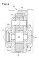
- Differential gear 23 is formed, as shown in more detail in Fig. 5.
- the gear 20 a at the same time the web of the differential gear 23 providing housing 24 has.
- the housing 24 or the gear 20 a are a central wheel 26 and a sun gear meshing therewith 27 mounted, in turn, with a toothed segment 28 in meshing engagement is.
- the toothed segment 28 diametrically opposite is at the central wheel 26th of the differential gear 23, a balance weight 29 is arranged.
- the integrated in the gears 20 a differential gear 23 allows a Centrifugal force can be generated with a large radius. The resulting, due The gear ratio still increased counter-torque can the differential centrifugal forces on both slides 3 a, 3 b in any position directly from the central Balance gear 20 a.
Landscapes
- Engineering & Computer Science (AREA)
- Mechanical Engineering (AREA)
- Transmission Devices (AREA)
- Cutting Tools, Boring Holders, And Turrets (AREA)
- Gear Transmission (AREA)
- Turning (AREA)
Priority Applications (1)
| Application Number | Priority Date | Filing Date | Title |
|---|---|---|---|
| PL05000194T PL1559494T3 (pl) | 2004-01-29 | 2005-01-07 | Urządzenie do obróbki końców rur, zwłaszcza do nacinania przyłączy gwintowanych |
Applications Claiming Priority (2)
| Application Number | Priority Date | Filing Date | Title |
|---|---|---|---|
| DE102004004498A DE102004004498A1 (de) | 2004-01-29 | 2004-01-29 | Vorrichtung zur Bearbeitung von Rohrenden, insbesondere zum Schneiden von Gewindeanschlüssen |
| DE102004004498 | 2004-01-29 |
Publications (3)
| Publication Number | Publication Date |
|---|---|
| EP1559494A2 true EP1559494A2 (fr) | 2005-08-03 |
| EP1559494A3 EP1559494A3 (fr) | 2006-01-18 |
| EP1559494B1 EP1559494B1 (fr) | 2012-10-24 |
Family
ID=34638799
Family Applications (1)
| Application Number | Title | Priority Date | Filing Date |
|---|---|---|---|
| EP05000194A Expired - Lifetime EP1559494B1 (fr) | 2004-01-29 | 2005-01-07 | Dispositif d'usinage d'extrémités de tubes, en particulier pour l'usinage des connexions filetées |
Country Status (7)
| Country | Link |
|---|---|
| US (1) | US7241086B2 (fr) |
| EP (1) | EP1559494B1 (fr) |
| JP (1) | JP4284281B2 (fr) |
| CN (1) | CN100537088C (fr) |
| DE (1) | DE102004004498A1 (fr) |
| ES (1) | ES2394658T3 (fr) |
| PL (1) | PL1559494T3 (fr) |
Cited By (6)
| Publication number | Priority date | Publication date | Assignee | Title |
|---|---|---|---|---|
| WO2009030210A1 (fr) * | 2007-09-06 | 2009-03-12 | CBS Präzisionswerkzeuge GmbH | Tête d'outil |
| WO2012100903A1 (fr) * | 2011-01-29 | 2012-08-02 | Sms Meer Gmbh | Machine d'usinage d'extrémités de tubes |
| WO2012136289A3 (fr) * | 2011-04-06 | 2012-12-06 | Sms Meer Gmbh | Dispositif de transport pour pièces possédant un axe longitudinal |
| DE102011111549A1 (de) * | 2011-08-24 | 2013-02-28 | MAPAL Fabrik für Präzisionswerkzeuge Dr. Kress KG | Werkzeug zum Bearbeiten von Werkstücken |
| IT201800005428A1 (it) * | 2018-05-16 | 2019-11-16 | Apparato di taglio per tubi plastici | |
| WO2020162812A1 (fr) * | 2019-02-05 | 2020-08-13 | M.P.C.-System Ab | Système de mandrin et procédé de fixation et de rotation d'une pièce à usiner à l'aide de celui-ci |
Families Citing this family (15)
| Publication number | Priority date | Publication date | Assignee | Title |
|---|---|---|---|---|
| CN1951613B (zh) * | 2005-10-21 | 2012-06-20 | 鸿富锦精密工业(深圳)有限公司 | 刀具结构 |
| KR20080026027A (ko) * | 2006-09-19 | 2008-03-24 | 유틸리스 아게 | 나사 선회가공 공구 |
| DE102006055417B4 (de) * | 2006-11-22 | 2010-05-20 | Rattunde & Co. Gmbh | Werkzeugkopf für eine Rohrschneidemaschine |
| DE102009053678A1 (de) | 2008-12-17 | 2010-09-16 | Sms Meer Gmbh | Zentriervorrichtung zum Zentrieren eines Werkstücks relativ zu einer Drehachse und Werkzeugmaschine |
| DE102009053679A1 (de) | 2008-12-17 | 2010-06-24 | Sms Meer Gmbh | Werkzeugmaschine zur Bearbeitung eines rohrförmigen Werkstücks |
| CN101870012B (zh) * | 2010-06-08 | 2013-01-23 | 兰州星火机床有限公司 | 多刀数控管子车床 |
| RU2474671C1 (ru) * | 2012-03-15 | 2013-02-10 | Общество с ограниченной ответственностью "Газпром газобезопасность" | Устройство для нарезания резьбы на трубах на устье скважин |
| MX2015001303A (es) | 2012-07-31 | 2015-04-08 | Sms Meer Gmbh | Maquina para el procesamiento de extremos de tubos con un dispositivo centrador para centrar una pieza de trabajo tubular en relacion a un eje de giro. |
| DE102013220617B3 (de) * | 2013-10-12 | 2015-03-26 | Battenfeld-Cincinnati Germany Gmbh | Ablängvorrichtung für extrudierte Kunststoffprofile |
| CN105772611A (zh) * | 2014-06-20 | 2016-07-20 | 高田华 | 螺纹转印装置 |
| CN109108395B (zh) * | 2018-11-06 | 2020-03-24 | 台州市硕阳机械股份有限公司 | 一种气罐端盖螺纹攻丝机 |
| CN110899574A (zh) * | 2019-11-25 | 2020-03-24 | 湖北工业大学 | 一种运用环切法切割钢绞线的装置 |
| CN112060456B (zh) * | 2020-09-08 | 2021-09-14 | 义乌宾创科技有限公司 | 一种节能环保的热水器保温材料灌注调节装置 |
| CH718197B1 (fr) * | 2020-12-21 | 2024-12-30 | Esco Sa | Unité d'usinage à tête rotative. |
| CN114083063B (zh) * | 2021-11-20 | 2022-12-13 | 贵溪世鹏金属有限公司 | 一种水暖管件的加工装置 |
Citations (2)
| Publication number | Priority date | Publication date | Assignee | Title |
|---|---|---|---|---|
| DE4438818A1 (de) | 1994-10-20 | 1996-05-02 | Mannesmann Ag | Vorrichtung zur Bearbeitung von Rohrenden |
| DE10133856A1 (de) | 2001-07-12 | 2003-01-30 | Koyemann Werkzeuge Gmbh & Co O | Werkzeugkopf mit Fliehkraftausgleich |
Family Cites Families (10)
| Publication number | Priority date | Publication date | Assignee | Title |
|---|---|---|---|---|
| US2131965A (en) * | 1936-06-16 | 1938-10-04 | Landis Machine Co | Thread forming mechanism |
| US2309862A (en) * | 1941-09-30 | 1943-02-02 | Landis Machine Co | Thread cutting mechanism |
| US3645638A (en) * | 1970-09-08 | 1972-02-29 | Pipe Machinery Co The | Method and apparatus for cutting threads |
| US3829920A (en) * | 1973-07-05 | 1974-08-20 | Pipe Machinery Co | Tool head with multiple tools and common oscillatable recede and collapse cam mechanism |
| US3992123A (en) * | 1975-10-01 | 1976-11-16 | The United States Of America As Represented By The Secretary Of The Navy | Pipe end machining apparatus |
| AT379096B (de) * | 1983-12-13 | 1985-11-11 | Heid Ag Maschf | Umlaufender bearbeitungskopf |
| EP0525406A1 (fr) * | 1991-07-17 | 1993-02-03 | BÜLTMANN, Monika | Dispositif de coupe de tubes |
| DE4428049C2 (de) * | 1994-08-09 | 2003-12-04 | Koyemann Werkzeuge Gmbh | Werkzeugkopf für Rohrgewindeschneidmaschinen |
| DE19531837A1 (de) * | 1995-08-29 | 1997-03-06 | Koyemann Werkzeuge Gmbh | Verstellvorrichtung für einen Werkzeugkopf |
| US6062777A (en) * | 1999-01-19 | 2000-05-16 | Usx Corporation | Machining threaded tubular goods |
-
2004
- 2004-01-29 DE DE102004004498A patent/DE102004004498A1/de not_active Withdrawn
-
2005
- 2005-01-07 PL PL05000194T patent/PL1559494T3/pl unknown
- 2005-01-07 ES ES05000194T patent/ES2394658T3/es not_active Expired - Lifetime
- 2005-01-07 EP EP05000194A patent/EP1559494B1/fr not_active Expired - Lifetime
- 2005-01-11 US US11/040,616 patent/US7241086B2/en not_active Expired - Fee Related
- 2005-01-31 CN CNB2005100061792A patent/CN100537088C/zh not_active Expired - Fee Related
- 2005-01-31 JP JP2005023275A patent/JP4284281B2/ja not_active Expired - Fee Related
Patent Citations (2)
| Publication number | Priority date | Publication date | Assignee | Title |
|---|---|---|---|---|
| DE4438818A1 (de) | 1994-10-20 | 1996-05-02 | Mannesmann Ag | Vorrichtung zur Bearbeitung von Rohrenden |
| DE10133856A1 (de) | 2001-07-12 | 2003-01-30 | Koyemann Werkzeuge Gmbh & Co O | Werkzeugkopf mit Fliehkraftausgleich |
Cited By (13)
| Publication number | Priority date | Publication date | Assignee | Title |
|---|---|---|---|---|
| WO2009030210A1 (fr) * | 2007-09-06 | 2009-03-12 | CBS Präzisionswerkzeuge GmbH | Tête d'outil |
| RU2563408C2 (ru) * | 2011-01-29 | 2015-09-20 | Смс Меер Гмбх | Станок для обработки концов труб |
| WO2012100903A1 (fr) * | 2011-01-29 | 2012-08-02 | Sms Meer Gmbh | Machine d'usinage d'extrémités de tubes |
| US9221103B2 (en) | 2011-01-29 | 2015-12-29 | Sms Meer Gmbh | Apparatus for machining the ends of pipes |
| CN103442844B (zh) * | 2011-04-06 | 2016-04-13 | Sms米尔股份有限公司 | 用于具有纵轴线的工件的运输装置 |
| RU2542958C1 (ru) * | 2011-04-06 | 2015-02-27 | Смс Меер Гмбх | Транспортировочное устройство для заготовок, имеющих продольную ось |
| CN103442844A (zh) * | 2011-04-06 | 2013-12-11 | Sms米尔股份有限公司 | 用于具有纵轴线的工件的运输装置 |
| WO2012136289A3 (fr) * | 2011-04-06 | 2012-12-06 | Sms Meer Gmbh | Dispositif de transport pour pièces possédant un axe longitudinal |
| DE102011111549A1 (de) * | 2011-08-24 | 2013-02-28 | MAPAL Fabrik für Präzisionswerkzeuge Dr. Kress KG | Werkzeug zum Bearbeiten von Werkstücken |
| US9242301B2 (en) | 2011-08-24 | 2016-01-26 | Mapal Fabrik Fur Prazisionswerkzeuge Dr. Kress Kg | Tool for processing work pieces |
| IT201800005428A1 (it) * | 2018-05-16 | 2019-11-16 | Apparato di taglio per tubi plastici | |
| EP3569350A1 (fr) * | 2018-05-16 | 2019-11-20 | Ipm S.R.L. | Dispositif de découpe de tubes en plastique |
| WO2020162812A1 (fr) * | 2019-02-05 | 2020-08-13 | M.P.C.-System Ab | Système de mandrin et procédé de fixation et de rotation d'une pièce à usiner à l'aide de celui-ci |
Also Published As
| Publication number | Publication date |
|---|---|
| EP1559494A3 (fr) | 2006-01-18 |
| CN1647878A (zh) | 2005-08-03 |
| CN100537088C (zh) | 2009-09-09 |
| PL1559494T3 (pl) | 2013-03-29 |
| ES2394658T3 (es) | 2013-02-04 |
| DE102004004498A1 (de) | 2005-08-18 |
| JP2005212096A (ja) | 2005-08-11 |
| JP4284281B2 (ja) | 2009-06-24 |
| EP1559494B1 (fr) | 2012-10-24 |
| US20050169722A1 (en) | 2005-08-04 |
| US7241086B2 (en) | 2007-07-10 |
Similar Documents
| Publication | Publication Date | Title |
|---|---|---|
| EP1559494B1 (fr) | Dispositif d'usinage d'extrémités de tubes, en particulier pour l'usinage des connexions filetées | |
| EP0707912B1 (fr) | Dispositif d'usinage d'extrémités de tubes | |
| DE102014213149B4 (de) | Kreisschiebeplanetenradgetriebe | |
| DE60036458T2 (de) | Drückwalzvorrichtung | |
| DE3324494C1 (de) | Walzwerkzeug | |
| DE3047550C2 (de) | Differentialgetriebe | |
| DE2613269C3 (fr) | ||
| EP3151986B1 (fr) | Dispositif pour incorporer un moulage en forme de bourrelet dans une partie de paroi d'un tube | |
| DE3238442C2 (de) | Fräsvorrichtung zum Erzeugen von Polygonprofilen | |
| DE10148503B4 (de) | Falzapparat mit umfangsverstellbarem Zylinder | |
| DE2814493A1 (de) | Verfahren zum herstellen duenner rohre sowie schraegwalzwerk zur durchfuehrung des verfahrens | |
| DE2156660A1 (de) | Vorrichtung und Verfahren zum Walzen von Zahnrädern | |
| DE102008006175B4 (de) | Werkzeugwechselvorrichtung | |
| DE1477275A1 (de) | Drehautomat | |
| DE602004007128T2 (de) | Vorrichtung zum synchronisierten relativ rotativen Antrieb zwischen Werkzeugen und einem zu bearbeitenden Werkstück um exzentrische Achsen. | |
| DD200364A1 (de) | Schaelmaschine | |
| EP3976303B1 (fr) | Fraise à tailler des engrenages et procédé pour fabriquer un engrenage à double denture hélicoïdale, ainsi qu'utilisation de la fraise à tailler des engrenages pour produire l'engrenage à double denture hélicoïdale | |
| DE3241676A1 (de) | Stufenlos regelbares uebersetzungsgetriebe und verfahren zur herstellung desselben | |
| DE2034315A1 (de) | Dreh- und Vorschubeinrichtung, vorzugsweise für Kaltpilgermaschinen | |
| EP0041150B1 (fr) | Dispositif pour retrousser axialement des boyaux tubulaires, en particulier pour la fabrication de saucisses | |
| DE1752285B2 (de) | Drehmaschine zum Herstellen von Werkstücken mit im Querschnitt regelmäßig unrunden und in Achsrichtung gewindeartig verlaufendem Außen- oder Innenmantelflächen | |
| DE1931860A1 (de) | Vorrichtung zur Umwandlung einer Drehbewegung in eine geradlinige Vorschubbewegung | |
| DE2652265A1 (de) | Spannfutter fuer kaltpilgerwalzwerke | |
| EP3816479B1 (fr) | Vis à rouleaux planétaires pour un broche télescopique sans glissement | |
| EP3672748B1 (fr) | Dispositif de serrage d'une pièce à usiner |
Legal Events
| Date | Code | Title | Description |
|---|---|---|---|
| PUAI | Public reference made under article 153(3) epc to a published international application that has entered the european phase |
Free format text: ORIGINAL CODE: 0009012 |
|
| AK | Designated contracting states |
Kind code of ref document: A2 Designated state(s): AT BE BG CH CY CZ DE DK EE ES FI FR GB GR HU IE IS IT LI LT LU MC NL PL PT RO SE SI SK TR |
|
| AX | Request for extension of the european patent |
Extension state: AL BA HR LV MK YU |
|
| PUAL | Search report despatched |
Free format text: ORIGINAL CODE: 0009013 |
|
| AK | Designated contracting states |
Kind code of ref document: A3 Designated state(s): AT BE BG CH CY CZ DE DK EE ES FI FR GB GR HU IE IS IT LI LT LU MC NL PL PT RO SE SI SK TR |
|
| AX | Request for extension of the european patent |
Extension state: AL BA HR LV MK YU |
|
| 17P | Request for examination filed |
Effective date: 20060711 |
|
| AKX | Designation fees paid |
Designated state(s): AT BE BG CH CY CZ DE DK EE ES FI FR GB GR HU IE IS IT LI LT LU MC NL PL PT RO SE SI SK TR |
|
| 17Q | First examination report despatched |
Effective date: 20061103 |
|
| GRAP | Despatch of communication of intention to grant a patent |
Free format text: ORIGINAL CODE: EPIDOSNIGR1 |
|
| GRAS | Grant fee paid |
Free format text: ORIGINAL CODE: EPIDOSNIGR3 |
|
| GRAA | (expected) grant |
Free format text: ORIGINAL CODE: 0009210 |
|
| AK | Designated contracting states |
Kind code of ref document: B1 Designated state(s): AT BE BG CH CY CZ DE DK EE ES FI FR GB GR HU IE IS IT LI LT LU MC NL PL PT RO SE SI SK TR |
|
| REG | Reference to a national code |
Ref country code: GB Ref legal event code: FG4D Free format text: NOT ENGLISH Ref country code: DE Ref legal event code: R081 Ref document number: 502005013198 Country of ref document: DE Owner name: SMS GROUP GMBH, DE Free format text: FORMER OWNER: SMS MEER GMBH, 41069 MOENCHENGLADBACH, DE |
|
| REG | Reference to a national code |
Ref country code: CH Ref legal event code: EP |
|
| REG | Reference to a national code |
Ref country code: AT Ref legal event code: REF Ref document number: 580632 Country of ref document: AT Kind code of ref document: T Effective date: 20121115 |
|
| REG | Reference to a national code |
Ref country code: IE Ref legal event code: FG4D Free format text: LANGUAGE OF EP DOCUMENT: GERMAN |
|
| REG | Reference to a national code |
Ref country code: DE Ref legal event code: R096 Ref document number: 502005013198 Country of ref document: DE Effective date: 20121220 |
|
| REG | Reference to a national code |
Ref country code: RO Ref legal event code: EPE |
|
| REG | Reference to a national code |
Ref country code: SE Ref legal event code: TRGR |
|
| REG | Reference to a national code |
Ref country code: ES Ref legal event code: FG2A Ref document number: 2394658 Country of ref document: ES Kind code of ref document: T3 Effective date: 20130204 |
|
| REG | Reference to a national code |
Ref country code: PL Ref legal event code: T3 |
|
| REG | Reference to a national code |
Ref country code: NL Ref legal event code: VDEP Effective date: 20121024 |
|
| PG25 | Lapsed in a contracting state [announced via postgrant information from national office to epo] |
Ref country code: IS Free format text: LAPSE BECAUSE OF FAILURE TO SUBMIT A TRANSLATION OF THE DESCRIPTION OR TO PAY THE FEE WITHIN THE PRESCRIBED TIME-LIMIT Effective date: 20130224 Ref country code: NL Free format text: LAPSE BECAUSE OF FAILURE TO SUBMIT A TRANSLATION OF THE DESCRIPTION OR TO PAY THE FEE WITHIN THE PRESCRIBED TIME-LIMIT Effective date: 20121024 Ref country code: FI Free format text: LAPSE BECAUSE OF FAILURE TO SUBMIT A TRANSLATION OF THE DESCRIPTION OR TO PAY THE FEE WITHIN THE PRESCRIBED TIME-LIMIT Effective date: 20121024 |
|
| PG25 | Lapsed in a contracting state [announced via postgrant information from national office to epo] |
Ref country code: SI Free format text: LAPSE BECAUSE OF FAILURE TO SUBMIT A TRANSLATION OF THE DESCRIPTION OR TO PAY THE FEE WITHIN THE PRESCRIBED TIME-LIMIT Effective date: 20121024 Ref country code: CY Free format text: LAPSE BECAUSE OF FAILURE TO SUBMIT A TRANSLATION OF THE DESCRIPTION OR TO PAY THE FEE WITHIN THE PRESCRIBED TIME-LIMIT Effective date: 20121024 Ref country code: GR Free format text: LAPSE BECAUSE OF FAILURE TO SUBMIT A TRANSLATION OF THE DESCRIPTION OR TO PAY THE FEE WITHIN THE PRESCRIBED TIME-LIMIT Effective date: 20130125 Ref country code: PT Free format text: LAPSE BECAUSE OF FAILURE TO SUBMIT A TRANSLATION OF THE DESCRIPTION OR TO PAY THE FEE WITHIN THE PRESCRIBED TIME-LIMIT Effective date: 20130225 |
|
| BERE | Be: lapsed |
Owner name: SMS MEER G.M.B.H. Effective date: 20130131 |
|
| PG25 | Lapsed in a contracting state [announced via postgrant information from national office to epo] |
Ref country code: SK Free format text: LAPSE BECAUSE OF FAILURE TO SUBMIT A TRANSLATION OF THE DESCRIPTION OR TO PAY THE FEE WITHIN THE PRESCRIBED TIME-LIMIT Effective date: 20121024 Ref country code: BG Free format text: LAPSE BECAUSE OF FAILURE TO SUBMIT A TRANSLATION OF THE DESCRIPTION OR TO PAY THE FEE WITHIN THE PRESCRIBED TIME-LIMIT Effective date: 20130124 Ref country code: EE Free format text: LAPSE BECAUSE OF FAILURE TO SUBMIT A TRANSLATION OF THE DESCRIPTION OR TO PAY THE FEE WITHIN THE PRESCRIBED TIME-LIMIT Effective date: 20121024 Ref country code: DK Free format text: LAPSE BECAUSE OF FAILURE TO SUBMIT A TRANSLATION OF THE DESCRIPTION OR TO PAY THE FEE WITHIN THE PRESCRIBED TIME-LIMIT Effective date: 20121024 |
|
| PG25 | Lapsed in a contracting state [announced via postgrant information from national office to epo] |
Ref country code: MC Free format text: LAPSE BECAUSE OF NON-PAYMENT OF DUE FEES Effective date: 20130131 |
|
| PLBE | No opposition filed within time limit |
Free format text: ORIGINAL CODE: 0009261 |
|
| REG | Reference to a national code |
Ref country code: CH Ref legal event code: PL |
|
| STAA | Information on the status of an ep patent application or granted ep patent |
Free format text: STATUS: NO OPPOSITION FILED WITHIN TIME LIMIT |
|
| 26N | No opposition filed |
Effective date: 20130725 |
|
| REG | Reference to a national code |
Ref country code: IE Ref legal event code: MM4A |
|
| PG25 | Lapsed in a contracting state [announced via postgrant information from national office to epo] |
Ref country code: CH Free format text: LAPSE BECAUSE OF NON-PAYMENT OF DUE FEES Effective date: 20130131 Ref country code: LI Free format text: LAPSE BECAUSE OF NON-PAYMENT OF DUE FEES Effective date: 20130131 Ref country code: BE Free format text: LAPSE BECAUSE OF NON-PAYMENT OF DUE FEES Effective date: 20130131 |
|
| REG | Reference to a national code |
Ref country code: DE Ref legal event code: R097 Ref document number: 502005013198 Country of ref document: DE Effective date: 20130725 |
|
| PG25 | Lapsed in a contracting state [announced via postgrant information from national office to epo] |
Ref country code: IE Free format text: LAPSE BECAUSE OF NON-PAYMENT OF DUE FEES Effective date: 20130107 |
|
| PG25 | Lapsed in a contracting state [announced via postgrant information from national office to epo] |
Ref country code: LT Free format text: LAPSE BECAUSE OF FAILURE TO SUBMIT A TRANSLATION OF THE DESCRIPTION OR TO PAY THE FEE WITHIN THE PRESCRIBED TIME-LIMIT Effective date: 20121024 |
|
| PG25 | Lapsed in a contracting state [announced via postgrant information from national office to epo] |
Ref country code: LU Free format text: LAPSE BECAUSE OF NON-PAYMENT OF DUE FEES Effective date: 20130107 Ref country code: HU Free format text: LAPSE BECAUSE OF FAILURE TO SUBMIT A TRANSLATION OF THE DESCRIPTION OR TO PAY THE FEE WITHIN THE PRESCRIBED TIME-LIMIT; INVALID AB INITIO Effective date: 20050107 |
|
| REG | Reference to a national code |
Ref country code: DE Ref legal event code: R082 Ref document number: 502005013198 Country of ref document: DE Representative=s name: HEMMERICH & KOLLEGEN, DE Ref country code: DE Ref legal event code: R081 Ref document number: 502005013198 Country of ref document: DE Owner name: SMS GROUP GMBH, DE Free format text: FORMER OWNER: SMS MEER GMBH, 41069 MOENCHENGLADBACH, DE |
|
| REG | Reference to a national code |
Ref country code: FR Ref legal event code: PLFP Year of fee payment: 12 |
|
| REG | Reference to a national code |
Ref country code: FR Ref legal event code: PLFP Year of fee payment: 13 |
|
| PGFP | Annual fee paid to national office [announced via postgrant information from national office to epo] |
Ref country code: PL Payment date: 20161223 Year of fee payment: 13 Ref country code: RO Payment date: 20161228 Year of fee payment: 13 |
|
| PGFP | Annual fee paid to national office [announced via postgrant information from national office to epo] |
Ref country code: DE Payment date: 20170120 Year of fee payment: 13 Ref country code: FR Payment date: 20170120 Year of fee payment: 13 Ref country code: SE Payment date: 20170119 Year of fee payment: 13 |
|
| PGFP | Annual fee paid to national office [announced via postgrant information from national office to epo] |
Ref country code: AT Payment date: 20170123 Year of fee payment: 13 Ref country code: CZ Payment date: 20170102 Year of fee payment: 13 Ref country code: GB Payment date: 20170119 Year of fee payment: 13 |
|
| PGFP | Annual fee paid to national office [announced via postgrant information from national office to epo] |
Ref country code: IT Payment date: 20170124 Year of fee payment: 13 Ref country code: TR Payment date: 20170104 Year of fee payment: 13 Ref country code: ES Payment date: 20170113 Year of fee payment: 13 |
|
| REG | Reference to a national code |
Ref country code: DE Ref legal event code: R119 Ref document number: 502005013198 Country of ref document: DE |
|
| REG | Reference to a national code |
Ref country code: SE Ref legal event code: EUG |
|
| REG | Reference to a national code |
Ref country code: AT Ref legal event code: MM01 Ref document number: 580632 Country of ref document: AT Kind code of ref document: T Effective date: 20180107 |
|
| GBPC | Gb: european patent ceased through non-payment of renewal fee |
Effective date: 20180107 |
|
| PG25 | Lapsed in a contracting state [announced via postgrant information from national office to epo] |
Ref country code: RO Free format text: LAPSE BECAUSE OF NON-PAYMENT OF DUE FEES Effective date: 20180107 Ref country code: SE Free format text: LAPSE BECAUSE OF NON-PAYMENT OF DUE FEES Effective date: 20180108 Ref country code: DE Free format text: LAPSE BECAUSE OF NON-PAYMENT OF DUE FEES Effective date: 20180801 Ref country code: FR Free format text: LAPSE BECAUSE OF NON-PAYMENT OF DUE FEES Effective date: 20180131 |
|
| REG | Reference to a national code |
Ref country code: FR Ref legal event code: ST Effective date: 20180928 |
|
| PG25 | Lapsed in a contracting state [announced via postgrant information from national office to epo] |
Ref country code: GB Free format text: LAPSE BECAUSE OF NON-PAYMENT OF DUE FEES Effective date: 20180107 Ref country code: CZ Free format text: LAPSE BECAUSE OF NON-PAYMENT OF DUE FEES Effective date: 20180107 Ref country code: AT Free format text: LAPSE BECAUSE OF NON-PAYMENT OF DUE FEES Effective date: 20180107 |
|
| PG25 | Lapsed in a contracting state [announced via postgrant information from national office to epo] |
Ref country code: IT Free format text: LAPSE BECAUSE OF NON-PAYMENT OF DUE FEES Effective date: 20180107 |
|
| REG | Reference to a national code |
Ref country code: ES Ref legal event code: FD2A Effective date: 20190730 |
|
| PG25 | Lapsed in a contracting state [announced via postgrant information from national office to epo] |
Ref country code: PL Free format text: LAPSE BECAUSE OF NON-PAYMENT OF DUE FEES Effective date: 20180107 |
|
| PG25 | Lapsed in a contracting state [announced via postgrant information from national office to epo] |
Ref country code: ES Free format text: LAPSE BECAUSE OF NON-PAYMENT OF DUE FEES Effective date: 20180108 |
|
| PG25 | Lapsed in a contracting state [announced via postgrant information from national office to epo] |
Ref country code: TR Free format text: LAPSE BECAUSE OF NON-PAYMENT OF DUE FEES Effective date: 20180107 |