EP1559535B1 - Pneumatique et son procédé de fabrication - Google Patents
Pneumatique et son procédé de fabrication Download PDFInfo
- Publication number
- EP1559535B1 EP1559535B1 EP04030835A EP04030835A EP1559535B1 EP 1559535 B1 EP1559535 B1 EP 1559535B1 EP 04030835 A EP04030835 A EP 04030835A EP 04030835 A EP04030835 A EP 04030835A EP 1559535 B1 EP1559535 B1 EP 1559535B1
- Authority
- EP
- European Patent Office
- Prior art keywords
- bead
- carcass ply
- tire
- apex
- core
- Prior art date
- Legal status (The legal status is an assumption and is not a legal conclusion. Google has not performed a legal analysis and makes no representation as to the accuracy of the status listed.)
- Expired - Lifetime
Links
- 238000004519 manufacturing process Methods 0.000 title claims abstract description 10
- 239000011324 bead Substances 0.000 claims abstract description 87
- 230000003014 reinforcing effect Effects 0.000 claims abstract description 33
- 229920001875 Ebonite Polymers 0.000 claims abstract description 5
- 238000004804 winding Methods 0.000 claims description 8
- 230000003247 decreasing effect Effects 0.000 description 6
- 238000000034 method Methods 0.000 description 6
- 239000013585 weight reducing agent Substances 0.000 description 6
- 229910000831 Steel Inorganic materials 0.000 description 5
- 239000010959 steel Substances 0.000 description 5
- 239000004677 Nylon Substances 0.000 description 3
- 239000000835 fiber Substances 0.000 description 3
- 229920001778 nylon Polymers 0.000 description 3
- 230000006866 deterioration Effects 0.000 description 2
- 230000008520 organization Effects 0.000 description 2
- 229920000139 polyethylene terephthalate Polymers 0.000 description 2
- 239000005020 polyethylene terephthalate Substances 0.000 description 2
- 239000004698 Polyethylene Substances 0.000 description 1
- 229920000297 Rayon Polymers 0.000 description 1
- 239000004760 aramid Substances 0.000 description 1
- 229920003235 aromatic polyamide Polymers 0.000 description 1
- 238000005452 bending Methods 0.000 description 1
- 230000001419 dependent effect Effects 0.000 description 1
- 230000002542 deteriorative effect Effects 0.000 description 1
- 239000000463 material Substances 0.000 description 1
- 229920000728 polyester Polymers 0.000 description 1
- -1 polyethylene Polymers 0.000 description 1
- 229920000573 polyethylene Polymers 0.000 description 1
- 239000002964 rayon Substances 0.000 description 1
- 238000000926 separation method Methods 0.000 description 1
- 230000008961 swelling Effects 0.000 description 1
- 230000001131 transforming effect Effects 0.000 description 1
Images


Classifications
-
- B—PERFORMING OPERATIONS; TRANSPORTING
- B60—VEHICLES IN GENERAL
- B60C—VEHICLE TYRES; TYRE INFLATION; TYRE CHANGING; CONNECTING VALVES TO INFLATABLE ELASTIC BODIES IN GENERAL; DEVICES OR ARRANGEMENTS RELATED TO TYRES
- B60C13/00—Tyre sidewalls; Protecting, decorating, marking, or the like, thereof
-
- B—PERFORMING OPERATIONS; TRANSPORTING
- B29—WORKING OF PLASTICS; WORKING OF SUBSTANCES IN A PLASTIC STATE IN GENERAL
- B29D—PRODUCING PARTICULAR ARTICLES FROM PLASTICS OR FROM SUBSTANCES IN A PLASTIC STATE
- B29D30/00—Producing pneumatic or solid tyres or parts thereof
- B29D30/06—Pneumatic tyres or parts thereof (e.g. produced by casting, moulding, compression moulding, injection moulding, centrifugal casting)
- B29D30/72—Side-walls
-
- B—PERFORMING OPERATIONS; TRANSPORTING
- B60—VEHICLES IN GENERAL
- B60C—VEHICLE TYRES; TYRE INFLATION; TYRE CHANGING; CONNECTING VALVES TO INFLATABLE ELASTIC BODIES IN GENERAL; DEVICES OR ARRANGEMENTS RELATED TO TYRES
- B60C15/00—Tyre beads, e.g. ply turn-up or overlap
- B60C15/06—Flipper strips, fillers, or chafing strips and reinforcing layers for the construction of the bead
-
- B—PERFORMING OPERATIONS; TRANSPORTING
- B60—VEHICLES IN GENERAL
- B60C—VEHICLE TYRES; TYRE INFLATION; TYRE CHANGING; CONNECTING VALVES TO INFLATABLE ELASTIC BODIES IN GENERAL; DEVICES OR ARRANGEMENTS RELATED TO TYRES
- B60C17/00—Tyres characterised by means enabling restricted operation in damaged or deflated condition; Accessories therefor
- B60C17/0009—Tyres characterised by means enabling restricted operation in damaged or deflated condition; Accessories therefor comprising sidewall rubber inserts, e.g. crescent shaped inserts
-
- B—PERFORMING OPERATIONS; TRANSPORTING
- B29—WORKING OF PLASTICS; WORKING OF SUBSTANCES IN A PLASTIC STATE IN GENERAL
- B29D—PRODUCING PARTICULAR ARTICLES FROM PLASTICS OR FROM SUBSTANCES IN A PLASTIC STATE
- B29D30/00—Producing pneumatic or solid tyres or parts thereof
- B29D30/06—Pneumatic tyres or parts thereof (e.g. produced by casting, moulding, compression moulding, injection moulding, centrifugal casting)
- B29D30/72—Side-walls
- B29D2030/722—Reinforcing the sidewalls, e.g. by using filaments, fibers or additional reinforcing layers
-
- Y—GENERAL TAGGING OF NEW TECHNOLOGICAL DEVELOPMENTS; GENERAL TAGGING OF CROSS-SECTIONAL TECHNOLOGIES SPANNING OVER SEVERAL SECTIONS OF THE IPC; TECHNICAL SUBJECTS COVERED BY FORMER USPC CROSS-REFERENCE ART COLLECTIONS [XRACs] AND DIGESTS
- Y10—TECHNICAL SUBJECTS COVERED BY FORMER USPC
- Y10T—TECHNICAL SUBJECTS COVERED BY FORMER US CLASSIFICATION
- Y10T152/00—Resilient tires and wheels
- Y10T152/10—Tires, resilient
- Y10T152/10495—Pneumatic tire or inner tube
- Y10T152/10819—Characterized by the structure of the bead portion of the tire
- Y10T152/10837—Bead characterized by the radial extent of apex, flipper or chafer into tire sidewall
-
- Y—GENERAL TAGGING OF NEW TECHNOLOGICAL DEVELOPMENTS; GENERAL TAGGING OF CROSS-SECTIONAL TECHNOLOGIES SPANNING OVER SEVERAL SECTIONS OF THE IPC; TECHNICAL SUBJECTS COVERED BY FORMER USPC CROSS-REFERENCE ART COLLECTIONS [XRACs] AND DIGESTS
- Y10—TECHNICAL SUBJECTS COVERED BY FORMER USPC
- Y10T—TECHNICAL SUBJECTS COVERED BY FORMER US CLASSIFICATION
- Y10T152/00—Resilient tires and wheels
- Y10T152/10—Tires, resilient
- Y10T152/10495—Pneumatic tire or inner tube
- Y10T152/10819—Characterized by the structure of the bead portion of the tire
- Y10T152/10846—Bead characterized by the chemical composition and or physical properties of elastomers or the like
-
- Y—GENERAL TAGGING OF NEW TECHNOLOGICAL DEVELOPMENTS; GENERAL TAGGING OF CROSS-SECTIONAL TECHNOLOGIES SPANNING OVER SEVERAL SECTIONS OF THE IPC; TECHNICAL SUBJECTS COVERED BY FORMER USPC CROSS-REFERENCE ART COLLECTIONS [XRACs] AND DIGESTS
- Y10—TECHNICAL SUBJECTS COVERED BY FORMER USPC
- Y10T—TECHNICAL SUBJECTS COVERED BY FORMER US CLASSIFICATION
- Y10T152/00—Resilient tires and wheels
- Y10T152/10—Tires, resilient
- Y10T152/10495—Pneumatic tire or inner tube
- Y10T152/10855—Characterized by the carcass, carcass material, or physical arrangement of the carcass materials
- Y10T152/10864—Sidewall stiffening or reinforcing means other than main carcass plies or foldups thereof about beads
Definitions
- the present invention relates to a pneumatic tire according to the preamble of claim 1 and to a method of manufacturing such a pneumatic tire.
- a pneumatic tire is provided with a bead apex (d) as shown in Fig.4.
- the bead apex (d) is made of a hard rubber and disposed between a main portion (b1) and a turnup portion (b2) of a carcass ply (b).
- the bead apex (d) extends from the bead core (c) into the sidewall portion to reinforce a bead portion (a) for the purpose of steering stability and the like.
- a small bead apex (d) is used, and in order to provide steering stability, instead of the radially outer portion of the large bead apex, a separate reinforcing rubber layer (f) is disposed between the main portion (b1) and a turnup portion (b2) of a carcass ply (b).
- the reinforcing rubber layer (f) is wound on the carcass ply main portion around the drum as shown in Fig.6(a), and then the carcass ply (b) is turned up. Thereafter, the cylindrical assembly including the carcass ply and reinforcing rubber layer is swollen into a toroidal shape. During swelling, however, as the reinforcing rubber layer (f) is stretched, the carcass cords are very likely to be disarranged in the turnup portion (b2) and the adjacent main portion (b1) of the carcass ply.
- EP-A-1 083 064 discloses a pneumatic tire according to the preamble of claim 1.
- US-A-4 214 620 a similar pneumatic tire is disclosed.
- an object of the present invention to provide a pneumatic tire and a method of manufacturing the same in which, by using a small bead apex rubber and a separate reinforcing rubber layer instead of a single large bead apex, while providing necessary steering stability and achieving an effective weight reduction, the above-mentioned problems are solved, namely, the deterioration in strength due to the residual internal stress can be avoided, and the disarrangement of the carcass cords during building a green tire can be prevented to improve tire uniformity.
- the normally inflated unloaded state is such that the tire is mounted on a standard wheel rim and inflate to a standard pressure but loaded with no tire load.
- the standard wheel rim is a wheel rim officially approved for the tire by standard organization, i.e. JATMA (Japan and Asia), T&RA (North America), ETRTO (Europe), STRO (Scandinavia) and the like.
- the standard pressure and a standard tire load are the maximum air pressure and the maximum tire load for the tire specified by the same organization in the Air-pressure/Maximum-load Table or similar list.
- the standard wheel rim is the "standard rim" specified in JATMA, the "Measuring Rim” in ETRTO, the "Design Rim” in TRA or the like.
- the standard pressure is the “maximum air pressure” in JATMA, the “Inflation Pressure” in ETRTO, the maximum pressure given in the “Tire Load Limits at various cold Inflation Pressures” table in TRA or the like.
- the standard load is the "maximum load capacity" in JATMA, the “Load Capacity” in ETRTO, the maximum value given in the above-mentioned table in TRA or the like. In case of passenger car tires, however, the standard pressure and standard tire load are uniformly defined by 180 kPa and 88 % of the maximum tire load, respectively.
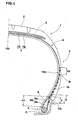
- pneumatic tire 1 is a radial tire for passenger cars comprising a tread portion 2, a pair of sidewall portions 3, a pair of bead portions 4, a carcass 6 extending between the bead portions through the tread portion and sidewall portions 3, and a belt 7,9 disposed radially outside the crown portion of the carcass 6 in the tread portion 2.
- Fig.1 the above-mentioned normally inflated unloaded state is shown.
- the bead portions 4 are each provided with a bead core 5.
- the bead core 5 is formed by winding a bead wire (for example steel wire) so that the windings make a ring with a specific cross-sectional shape (or arrangement).
- a single steel wire having a diameter of from 0.8 to 1.5 mm is wound into a circular cross sectional shape because a circular shape can decrease the axial width of the bead core, and as a result the volume of the bead portion 4 can be decreased to reduce the tire weight.
- so called cable bead formed by winding a sheathe wire or wires helically around an annular core wire can be used as another cord structure having a round cross-sectional shape.
- a bead apex 8 made of a hard rubber is disposed on the radially outside of the bead core 5.
- the bead apex 8 extends radially outwards from the bead core 5 and tapers radially outwardly so that the thickness becomes zero at its radially outer end.
- the radial height H1 of the bead apex 8 measured between the radially outer end and the bead core 5 is decreased to within a range of from 10 to 25 mm. Thereby, it is possible to slim down the bead portion 4 to achieve both of the ride comfort and tire weight reduction.
- the carcass 6 is composed of at least one ply 6A of cords arranged radially at an angle in the range of from 70 to 90 degrees with respect to the tire equator CO, extending between the bead portions 4 through the tread portion 2 and sidewall portions 3 and turned up around the bead core 5 in each bead portion 4 from the axially inside to the axially outside of the tire to form a pair of turnup portions 6b and a main portion 6a therebetween.
- the carcass 6 is composed of a single ply 6A of cords arranged radially at 90 degrees with respect to the tire equator CO.
- organic fiber cords e.g. polyester, nylon, rayon and the like can be suitably used.
- the belt comprises a breaker 7 and optionally a band 9.
- the breaker 7 comprises at least two cross plies 7A and 7B of high modulus cords laid at an angle of from 10 to 35 degrees with respect to the tire equator CO.
- steel cords and/or high modulus organic fiber cords such as polyethylene naphtarete(PEN), polyethylene terephthalate(PET) and aromatic polyamide can be used.
- the breaker consists of the two cross breaker plies 7A and 7B.
- the band 9 is composed of a cord or cords wound on the radially outside of the breaker at a small angle of at most about 5 degrees, or almost zero degree with respect to the tire equator CO.
- organic fiber cords such as nylon are used.
- the band 9 is a single full width nylon band covering the overall width of the breaker 7.
- a so called edge band made up of two parts covering the edge portions of the breaker only can be used alone or in combination with the full width band.
- the above-mentioned bead apex 8 is disposed between the carcass main portion 6a and turnup portion 6b.
- the carcass ply turnup portion 6b extends radially outwardly along the axially outside of the bead apex 8, and then beyond the radially outer end of the bead apex, it extends along the axially outside of the carcass main portion 6a.
- a reinforcing rubber layer 10 is disposed on the axially outside of the carcass 6, a reinforcing rubber layer 10 is disposed.
- This layer 10 is made of a hard rubber of which hardness is the same order as the bead apex such that the difference therebetween is less than 15 degrees in JIS type-A durometer hardness measured according to Japanese Industrial Standard K6253.
- the JIS type-A durometer hardness of the reinforcing rubber layer 10 is set in the range of from 75 to 95 degrees.
- the reinforcing rubber layer 10 has a substantially constant thickness of from 0.5 to 1.5 mm.
- the reinforcing rubber layer 10 extends radially outwardly beyond the maximum tire section width point M, and the radially outer end portion 10U terminates on the axially outside of the carcass main portion 6a at a radially height H2 of from 5 to 15 mm from the maximum tire section width point M.
- the radially inner end portion 10L overlaps with the turnup portion 6b and terminates on the axially outside of the carcass turnup portion 6b. Further, the radially inner end portion 10L overlaps with the bead apex 8 in the radial direction.
- the overlap Y of the radially inner end portion 10L with the bead apex 8 is set in the range of from 5 to 20 mm in the radial direction of the tire.
- the overlap X of the radially inner end portion 10L with the turnup portion 6b is set in a range of not less than 5 mm along the layer 10.
- the reinforcing rubber layer 10 reinforce the bead portion and sidewall lower portion to thereby provide the necessary steering stability while achieving the ride comfort and effective weight reduction.
- the rigidity variation from the radially inner end portion 10L to the bead apex 8 makes a smooth or gradual change. Further, as the radially outer edge of the turnup portion 6b is covered, failure such as separation can be effectively prevented.
- the hardness of the reinforcing rubber layer 10 is less than 75 degrees and/or the thickness is less than 0.5 mm, then the reinforcing becomes insufficient and it becomes difficult to improve the steering stability. If the hardness is more than 95 degrees and/or the thickness is more than 1.5 mm, then the ride comfort is liable to deteriorate.
- the overlap Y is less than 5 mm, the overlapped portion is liable to become weak, and it becomes difficult to improve the steering stability.
- the overlap Y of more than 20 mm is not preferable in view of tire weight reduction.
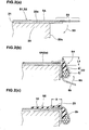
- Figs.2(a)-2(c) show part of a method of manufacturing the pneumatic tire 1.
- the method comprises the following steps (S1)-(S9).
- Figs.3(a), 3(b) and 3(c) show another example of the part of the method shown in Figs.2(a)-2(c), wherein the step (s6) of winding the reinforcing rubber layer shown in Fig.2(c) is committed. Only the differences from the former example will be described.
- the overlap therebetween namely, the above-mentioned overlap x of the radially inner end portion 10L with the turnup portion 6b is set in a range of not less than 5 mm not to separate from each other during the following turning down step (Fig.3(b)) and turning up step (Fig.3(c)).
- the protruding portion 23 inclusive of the reinforcing rubber layer 10 is turned down along a radial surface 20s as show in Fig.3(b).
- the bead-core assembly 22 is pressed, and the protruding portion 23 is turned up around the bead core assembly 22 onto the main portion 6a of the carcass ply 6A together with the reinforcing rubber layer 10 as shown in Fig.3(c).
- the green tire is made, and vulcanized to the finished product.
- test tires of size 175/65R14 for passenger cars were made based on the specifications given in Table 1.
- the tires were tested for the steering stability and ride comfort. Also, the vertical spring constant and lateral spring constant of the tire were measured.
- a test tire mounted on a standard rim and inflated to 200 kPa was measured for vertical deflection during applying a vertical load of 4.0 kN, and the vertical spring constant was obtained as the quotient of the vertical load divided by the vertical deflection.
- a lateral force of 500 N was further applied to the tire and the lateral deflection of the tire was measured, and the lateral spring constant was obtained as the quotient of the lateral force divided by the lateral deflection.
- the spring constants are indicated in Table 1 by an index based on conventional tire being 100.
- a 1500cc FF passenger car provided on all the four wheels with test tires (tire pressure 200 kPa) was run on a dry tire test course, and the test driver evaluated steering stability and ride comfort.
- the results are indicated in Table 1 by an index based on Conventional tire being 100. The larger the index, the better the performance.
Landscapes
- Engineering & Computer Science (AREA)
- Mechanical Engineering (AREA)
- Tires In General (AREA)
- Tyre Moulding (AREA)
Claims (5)
- Bandage pneumatique (1) comprenant :une partie de bande de roulement (2),une paire de parties de paroi latérale (3),une paire de parties de talon (4), chacune avec une tringle (5) à l'intérieur,un pli de carcasse (6) s'étendant entre les parties de talon (4) en passant par la partie de bande de roulement (2) et les parties de paroi latérale (3), et retourné autour de la tringle (5) dans chacune des parties de talon (4) de l'intérieur à l'extérieur du bandage afin de former une paire de parties retournées (6b) et une partie principale (6a) entre elles,un sommet de talon (8) disposé entre chacune desdites parties retournées (6b) et ladite partie principale (6a), etune couche de caoutchouc de renforcement (10) disposée de manière axiale à l'extérieur dudit pli de carcasse (6),dans lequel
ladite couche de caoutchouc de renforcement (10) s'étend radialement vers l'extérieur au-delà du point de largeur de section de bandage maximum (M) et radialement vers l'intérieur au-delà du bord radialement externe de la partie retournée (6b), et
le sommet de talon (8) et la couche de caoutchouc de renforcement (10) sont chacun réalisés à partir d'un caoutchouc dur,
caractérisé en ce que
ledit sommet de talon (8) s'étend radialement vers l'extérieur à partir de la tringle (5) jusqu'à une position située à une hauteur radiale (H1) de l'ordre de 10 à 25 mm à partir de l'extrémité radialement externe de la tringle (5),
ladite couche de caoutchouc de renforcement (10) chevauche avec l'extrémité radialement externe du sommet de talon (8), et le chevauchement (Y) entre eux est de l'ordre de 5 à 20 mm dans la direction radiale du bandage, et
la différence de dureté entre ledit sommet de talon (8) et ladite couche de caoutchouc de renforcement (10) n'est pas supérieure à 15 degrés. - Bandage pneumatique (1) selon la revendication 1, dans lequel
la dureté de la couche de caoutchouc de renforcement (10) est de l'ordre de 75 à 95 degrés, et
son épaisseur est de l'ordre de 0,5 à 1,5 mm. - Bandage pneumatique (1) selon la revendication 1, dans lequel ladite tringle (5) a une forme transversale ronde.
- Procédé de fabrication d'un bandage pneumatique (1) selon l'une quelconque des revendications 1 à 3, comprenant les étapes consistant à :enrouler un pli de carcasse (6A) autour d'une surface cylindrique (20c) d'un tambour de fabrication de bandage (20) de sorte que les parties de bord (23) du pli de carcasse (6A) font saillie des bords de la surface cylindrique (20c) ;placer un ensemble de tringle et de sommet (22) sur chaque côté de la surface cylindrique (20c), dans lequel l'ensemble de tringle et de sommet (22) est composé d'une tringle annulaire (5) et d'un caoutchouc de sommet de talon annulaire (8) s'étendant de manière radiale autour de la tringle (5), et l'extrémité radialement externe du caoutchouc de sommet de talon (8) est positionnée à une distance radiale (L1) non supérieure à 8 mm de la surface cylindrique (20c) ;retourner les parties de bord en saillie (23) du pli de carcasse (6A) autour de l'ensemble de tringle et de sommet (22) de l'intérieur axial jusqu'à l'extérieur axial sur la partie principale de pli de carcasse (6a) enroulée autour d'un tambour de fabrication de bandage (20), de sorte que l'extrémité radialement externe du caoutchouc de sommet de talon (8) est pliée conjointement aux parties de bord en saillie (23) du pli de carcasse (6A) de l'extérieur axial jusqu'à l'intérieur axial sur la partie principale de pli de carcasse (6a) ; etenrouler une couche de caoutchouc de renforcement (10) autour de la partie principale (6a) et chacune des parties de bord retournées (6b) du pli de carcasse (6A) de sorte de la couche de caoutchouc de renforcement (10) chevauche avec la partie de bord retournée (6b) et le chevauchement entre eux n'est pas inférieur à 5 mm.
- Procédé de fabrication d'un bandage pneumatique (1) selon l'une quelconque des revendications 1 à 3, comprenant les étapes consistant à :enrouler un pli de carcasse (6A) autour d'une surface cylindrique (20c) d'un tambour de fabrication de bandage (20) de sorte que les parties de bord (23) du pli de carcasse (6A) font saillie des bords de la surface cylindrique (20c), dans lequel les parties de bord en saillie (23) du pli de carcasse (6A) sont chacune prévues sur la surface radialement interne avec une couche de caoutchouc de renforcement (10) de sorte que la partie de caoutchouc de renforcement (10) chevauche au moins de 5 mm avec la partie de bord (23) ;placer un ensemble de tringle et de sommet (22) de chaque côté de la surface cylindrique (20c), dans lequel l'ensemble de tringle et de sommet (22) est composé d'une tringle annulaire (5) et d'un caoutchouc de sommet de talon annulaire (8) s'étendant de manière radiale autour de la tringle (5) et la partie radialement externe du caoutchouc de sommet de talon (8) est positionnée au niveau d'une distance radiale (L1) non supérieure à 8 mm de la surface cylindrique (22c) ; etretourner les parties de bord en saillie (23) du pli de carcasse (6A) conjointement aux couches de caoutchouc de renforcement (10), autour de l'ensemble de tringle et de sommet (22) de l'intérieur axial jusqu'à l'extérieur axial sur la partie principale (6a) de pli de carcasse entourée autour du tambour de fabrication de bandage (20), de sorte que l'extrémité radialement externe du caoutchouc de sommet de talon (8) est pliée conjointement aux parties de bord en saillie (23) du pli de carcasse (6A) de l'extérieur axial jusqu'à l'intérieur axial sur la partie principale (6a) de pli de carcasse.
Applications Claiming Priority (2)
| Application Number | Priority Date | Filing Date | Title |
|---|---|---|---|
| JP2004020224 | 2004-01-28 | ||
| JP2004020224A JP4464700B2 (ja) | 2004-01-28 | 2004-01-28 | 空気入りタイヤ及びその製造方法 |
Publications (2)
| Publication Number | Publication Date |
|---|---|
| EP1559535A1 EP1559535A1 (fr) | 2005-08-03 |
| EP1559535B1 true EP1559535B1 (fr) | 2007-12-19 |
Family
ID=34650799
Family Applications (1)
| Application Number | Title | Priority Date | Filing Date |
|---|---|---|---|
| EP04030835A Expired - Lifetime EP1559535B1 (fr) | 2004-01-28 | 2004-12-27 | Pneumatique et son procédé de fabrication |
Country Status (5)
| Country | Link |
|---|---|
| US (1) | US7316255B2 (fr) |
| EP (1) | EP1559535B1 (fr) |
| JP (1) | JP4464700B2 (fr) |
| CN (1) | CN100393507C (fr) |
| DE (1) | DE602004010774T2 (fr) |
Families Citing this family (34)
| Publication number | Priority date | Publication date | Assignee | Title |
|---|---|---|---|---|
| DE102005003856A1 (de) * | 2005-01-27 | 2006-08-03 | Continental Aktiengesellschaft | Verfahren zur Herstellung eines Luftreifens mit Reifenaufbauteilen |
| JP2007290299A (ja) * | 2006-04-27 | 2007-11-08 | Bridgestone Corp | 空気入りラジアルタイヤの製造方法および空気ラジアルタイヤ |
| JP2008155728A (ja) * | 2006-12-22 | 2008-07-10 | Sumitomo Rubber Ind Ltd | 空気入りタイヤ |
| CN101600562B (zh) | 2007-02-15 | 2014-09-10 | 倍耐力轮胎股份公司 | 用于制造轮胎的方法和设备 |
| KR20090118903A (ko) * | 2007-02-15 | 2009-11-18 | 바텔 머시너리 시스템즈, 엘.엘.씨. | 테이퍼진 비드를 포함하는 타이어 및 타이어 제조 방법 |
| JP2009001073A (ja) * | 2007-06-19 | 2009-01-08 | Yokohama Rubber Co Ltd:The | 空気入りラジアルタイヤ |
| JP5104091B2 (ja) * | 2007-07-19 | 2012-12-19 | 横浜ゴム株式会社 | 空気入りタイヤ |
| JP4728304B2 (ja) * | 2007-09-04 | 2011-07-20 | 住友ゴム工業株式会社 | 空気入りタイヤ |
| ATE512790T1 (de) | 2007-11-15 | 2011-07-15 | Pirelli | Verfahren zur herstellung von reifen für fahrzeugräder und vorrichtung zum bau einer karkassenstruktur eines reifens für fahrzeugräder |
| KR101573305B1 (ko) * | 2008-04-14 | 2015-12-01 | 후지 세이코 가부시키가이샤 | 비드 와이어의 권취 및 성형 장치 |
| JP5358681B2 (ja) * | 2008-05-28 | 2013-12-04 | ピレリ・タイヤ・ソチエタ・ペル・アツィオーニ | タイヤを構築する方法および装置 |
| US9266399B2 (en) * | 2010-12-14 | 2016-02-23 | Compagnie Generale Des Etablissements Michelin | Tire with improved beads |
| JP5232254B2 (ja) * | 2011-01-17 | 2013-07-10 | 住友ゴム工業株式会社 | ビードエイペックス用ゴム組成物及び空気入りタイヤ |
| FR2971733B1 (fr) * | 2011-02-17 | 2013-02-22 | Michelin Soc Tech | Pneumatique ayant des bourrelets perfectionnes. |
| JP5416190B2 (ja) * | 2011-03-17 | 2014-02-12 | 住友ゴム工業株式会社 | ビードエイペックス用ゴム組成物及び空気入りタイヤ |
| JP5346365B2 (ja) * | 2011-04-11 | 2013-11-20 | 住友ゴム工業株式会社 | ビードエイペックス用ゴム組成物及び空気入りタイヤ |
| KR101269521B1 (ko) | 2011-11-04 | 2013-05-31 | 한국타이어 주식회사 | 중하중용 공기입 타이어 |
| JP6227855B2 (ja) * | 2011-12-05 | 2017-11-08 | 東洋ゴム工業株式会社 | 空気入りタイヤ |
| US20130340911A1 (en) * | 2012-06-20 | 2013-12-26 | Erich Nicolaus Lemaire | Bead core-apex subassembly, pneumatic tire therewith and method of manufacturing a bead core-apex subassembly |
| EP2983903B1 (fr) | 2013-04-10 | 2018-08-01 | Pirelli Tyre S.p.A. | Procédé et moule de vulcanisation pour la fabrication de pneus pour roues de véhicules |
| WO2015015336A1 (fr) * | 2013-08-01 | 2015-02-05 | Pirelli Tyre S.P.A. | Procédé et appareil de fabrication de pneus pour roues de véhicule et pneu pour roues de véhicule |
| JP6494029B2 (ja) * | 2015-07-13 | 2019-04-03 | 住友ゴム工業株式会社 | 空気入りタイヤ |
| JP6774307B2 (ja) * | 2016-11-09 | 2020-10-21 | Toyo Tire株式会社 | 空気入りタイヤ |
| JP6779780B2 (ja) * | 2016-12-28 | 2020-11-04 | Toyo Tire株式会社 | 空気入りタイヤ |
| KR101973273B1 (ko) * | 2017-09-11 | 2019-04-26 | 금호타이어 주식회사 | 공기입 레디얼 타이어 |
| JP6972975B2 (ja) * | 2017-11-29 | 2021-11-24 | 横浜ゴム株式会社 | 空気入りタイヤ |
| CN110171254B (zh) * | 2019-06-26 | 2024-03-01 | 青岛双星轮胎工业有限公司 | 钢丝胎体乘用轮胎子口结构 |
| JP7388056B2 (ja) * | 2019-08-29 | 2023-11-29 | 住友ゴム工業株式会社 | 空気入りタイヤ |
| JP2021123197A (ja) * | 2020-02-04 | 2021-08-30 | 住友ゴム工業株式会社 | 空気入りタイヤ |
| JP7484507B2 (ja) * | 2020-07-08 | 2024-05-16 | 住友ゴム工業株式会社 | 空気入りタイヤ |
| JP7140310B1 (ja) * | 2020-10-07 | 2022-09-21 | 住友ゴム工業株式会社 | タイヤ |
| JP7092233B1 (ja) * | 2021-04-19 | 2022-06-28 | 住友ゴム工業株式会社 | タイヤ |
| JP7806504B2 (ja) * | 2022-01-12 | 2026-01-27 | 住友ゴム工業株式会社 | 空気入りタイヤ |
| JP7838323B2 (ja) * | 2022-03-09 | 2026-04-01 | 住友ゴム工業株式会社 | 空気入りタイヤ |
Family Cites Families (16)
| Publication number | Priority date | Publication date | Assignee | Title |
|---|---|---|---|---|
| IT1045356B (it) * | 1973-06-12 | 1980-05-10 | Pirelli | Perfezionamento ai pneumatici radiali provvisti di struttura di irrigidimento circonferenziale dei fianchi |
| JPS586738B2 (ja) * | 1978-08-25 | 1983-02-05 | 横浜ゴム株式会社 | 高硬度ゴム組成物 |
| JPS589005B2 (ja) * | 1979-05-04 | 1983-02-18 | 横浜ゴム株式会社 | 空気入りタイヤ |
| US4872497A (en) * | 1984-11-26 | 1989-10-10 | The Yokohama Rubber Co., Ltd. | Pneumatic radial tire and rim combination for passenger car |
| US5522443A (en) * | 1990-03-16 | 1996-06-04 | Sumitomo Rubber Industries, Ltd. | High speed heavy duty tire and rim assembly whose tire includes a buffer layer in each bead portion |
| JP3706181B2 (ja) * | 1994-12-09 | 2005-10-12 | 株式会社ブリヂストン | 空気入りラジアルタイヤ |
| FR2763894A1 (fr) * | 1997-05-30 | 1998-12-04 | Michelin & Cie | Enveloppe de pneumatiques dont chaque bourrelet comporte deux tringles |
| JPH1120404A (ja) * | 1997-06-27 | 1999-01-26 | Bridgestone Corp | 空気入りタイヤ |
| JP3332330B2 (ja) | 1997-06-27 | 2002-10-07 | 住友ゴム工業株式会社 | 空気入りタイヤ及びその製造方法 |
| KR100577589B1 (ko) * | 1997-07-01 | 2006-05-08 | 스미토모 고무 고교 가부시키가이샤 | 중하중용 레이디얼 타이어 |
| FR2773519B1 (fr) * | 1998-01-12 | 2000-02-11 | Michelin & Cie | Bourrelet de pneumatique avec elements de renfort circonferentiels |
| FR2779387B1 (fr) * | 1998-06-05 | 2000-08-11 | Michelin & Cie | Bourrelet renforce de pneumatique radial |
| JP2001071715A (ja) * | 1999-09-09 | 2001-03-21 | Bridgestone Corp | 空気入りタイヤ |
| US6972061B1 (en) * | 1999-12-06 | 2005-12-06 | The Goodyear Tire & Rubber Company | Compound apex for vehicle tire |
| JP4590785B2 (ja) * | 2001-06-19 | 2010-12-01 | パナソニック株式会社 | 非接触型位置センサ |
| US20050028920A1 (en) * | 2003-08-04 | 2005-02-10 | Roedseth John Kolbjoern | High crown first stage tire building drum |
-
2004
- 2004-01-28 JP JP2004020224A patent/JP4464700B2/ja not_active Expired - Fee Related
- 2004-12-27 DE DE602004010774T patent/DE602004010774T2/de not_active Expired - Lifetime
- 2004-12-27 EP EP04030835A patent/EP1559535B1/fr not_active Expired - Lifetime
-
2005
- 2005-01-04 US US11/027,943 patent/US7316255B2/en not_active Expired - Fee Related
- 2005-01-28 CN CNB2005100051381A patent/CN100393507C/zh not_active Expired - Fee Related
Also Published As
| Publication number | Publication date |
|---|---|
| CN100393507C (zh) | 2008-06-11 |
| US20050161141A1 (en) | 2005-07-28 |
| DE602004010774T2 (de) | 2008-12-24 |
| JP2005212563A (ja) | 2005-08-11 |
| CN1647958A (zh) | 2005-08-03 |
| DE602004010774D1 (de) | 2008-01-31 |
| JP4464700B2 (ja) | 2010-05-19 |
| US7316255B2 (en) | 2008-01-08 |
| EP1559535A1 (fr) | 2005-08-03 |
Similar Documents
| Publication | Publication Date | Title |
|---|---|---|
| US7316255B2 (en) | Pneumatic tire and method of manufacturing the same | |
| US6053229A (en) | Pneumatic tire with specified bead filler height and method of manufacturing the same | |
| EP2014452B1 (fr) | Procédé de fabrication d'un pneumatique. | |
| EP1666236B1 (fr) | Pneumatique | |
| EP2308694B1 (fr) | Pneu | |
| EP1702744B1 (fr) | Pneumatique pour deux-roues et procédé de fabrication de pneumatique | |
| US7128114B2 (en) | Pneumatic tire and method of manufacturing the tire | |
| CN106994865B (zh) | 充气轮胎 | |
| US7628190B2 (en) | Pneumatic tire and manufacturing method of the same | |
| EP2974891B1 (fr) | Pneumatique | |
| CN100572107C (zh) | 具有改进的高速性能的轮胎以及制造方法 | |
| EP1612057B1 (fr) | Pneumatique | |
| EP1859924B1 (fr) | Methode de production de pneus | |
| EP3351406B1 (fr) | Pneumatique | |
| EP1705035A1 (fr) | Pneumatique | |
| EP3366496B1 (fr) | Pneu de roulage à plat et son procédé de fabrication | |
| EP1488939B1 (fr) | Pneumatique | |
| EP3536522B1 (fr) | Pneumatique de roulage à plat | |
| US10232668B2 (en) | Pneumatic tire with carcass ply overlap | |
| EP1782971B1 (fr) | Pneumatique pour motocyclette | |
| JPH08175122A (ja) | 乗用車用空気入りラジアルタイヤ | |
| JP7424070B2 (ja) | タイヤの製造方法及び生タイヤ | |
| US20070051454A1 (en) | Producing method of pneumatic tire | |
| JPH1128915A (ja) | 空気入りタイヤ及びその成形方法 | |
| JP2018075976A (ja) | 空気入りタイヤ |
Legal Events
| Date | Code | Title | Description |
|---|---|---|---|
| PUAI | Public reference made under article 153(3) epc to a published international application that has entered the european phase |
Free format text: ORIGINAL CODE: 0009012 |
|
| AK | Designated contracting states |
Kind code of ref document: A1 Designated state(s): AT BE BG CH CY CZ DE DK EE ES FI FR GB GR HU IE IS IT LI LT LU MC NL PL PT RO SE SI SK TR |
|
| AX | Request for extension of the european patent |
Extension state: AL BA HR LV MK YU |
|
| 17P | Request for examination filed |
Effective date: 20060118 |
|
| AKX | Designation fees paid |
Designated state(s): DE FR GB |
|
| GRAP | Despatch of communication of intention to grant a patent |
Free format text: ORIGINAL CODE: EPIDOSNIGR1 |
|
| GRAS | Grant fee paid |
Free format text: ORIGINAL CODE: EPIDOSNIGR3 |
|
| GRAA | (expected) grant |
Free format text: ORIGINAL CODE: 0009210 |
|
| AK | Designated contracting states |
Kind code of ref document: B1 Designated state(s): DE FR GB |
|
| REG | Reference to a national code |
Ref country code: GB Ref legal event code: FG4D |
|
| REF | Corresponds to: |
Ref document number: 602004010774 Country of ref document: DE Date of ref document: 20080131 Kind code of ref document: P |
|
| ET | Fr: translation filed | ||
| PLBE | No opposition filed within time limit |
Free format text: ORIGINAL CODE: 0009261 |
|
| STAA | Information on the status of an ep patent application or granted ep patent |
Free format text: STATUS: NO OPPOSITION FILED WITHIN TIME LIMIT |
|
| 26N | No opposition filed |
Effective date: 20080922 |
|
| PGFP | Annual fee paid to national office [announced via postgrant information from national office to epo] |
Ref country code: GB Payment date: 20101222 Year of fee payment: 7 |
|
| PGFP | Annual fee paid to national office [announced via postgrant information from national office to epo] |
Ref country code: FR Payment date: 20111219 Year of fee payment: 8 |
|
| PGFP | Annual fee paid to national office [announced via postgrant information from national office to epo] |
Ref country code: DE Payment date: 20111221 Year of fee payment: 8 |
|
| GBPC | Gb: european patent ceased through non-payment of renewal fee |
Effective date: 20121227 |
|
| REG | Reference to a national code |
Ref country code: FR Ref legal event code: ST Effective date: 20130830 |
|
| REG | Reference to a national code |
Ref country code: DE Ref legal event code: R119 Ref document number: 602004010774 Country of ref document: DE Effective date: 20130702 |
|
| PG25 | Lapsed in a contracting state [announced via postgrant information from national office to epo] |
Ref country code: DE Free format text: LAPSE BECAUSE OF NON-PAYMENT OF DUE FEES Effective date: 20130702 |
|
| PG25 | Lapsed in a contracting state [announced via postgrant information from national office to epo] |
Ref country code: FR Free format text: LAPSE BECAUSE OF NON-PAYMENT OF DUE FEES Effective date: 20130102 Ref country code: GB Free format text: LAPSE BECAUSE OF NON-PAYMENT OF DUE FEES Effective date: 20121227 |